Note: Descriptions are shown in the official language in which they were submitted.
CA 02522371 2005-10-05
TAIL LAMP STRUCTURE FOR VEHICLES
FIELD OF THE INVENTION
The present invention relates to a tail lamp structure for a vehicle.
BACKGROUND OF THE INVENTION
As a tail lamp structure for a vehicle, the one using a light-emitting diode
as a
light source for improving visibility is put to practical use.
The tail lamp structure for a vehicle in which the light-emitting diodes are
arranged on a board, the board and the light-emitting diodes are arranged in
a housing, and a lens is covered on the housing in practical use was
sufficient
for practical use.
As the tail lamp structure for a vehicle as described above, the one shown
below is known (for example, see JP-A-2002-337775 (p.8, Fig. 6).
In the tail lamp structure for a vehicle, since it relates significantly to
the
design of its appearance, it has been required to have high flexibility in
design, and hence it is required to devise the arrangement structure of a
light-
emitting diode board (sub-board) for mounting light emitting diodes (LED)
thereon, a control element board (main board) for mounting a control element
for controlling the light-emitting diode, a housing for storing the light-
emitting diode board and the control element board, a lens for covering the
housing, a harness (wiring member) extended from the control element board
and led outward from the housing, and a connector attached to the distal end
of the harness.
WH-12783/cs
CA 02522371 2005-10-05
-2-
In particular, in the case of the tail lamp structure using the light-emitting
diode, the dimension in the vertical direction can be reduced easily, but the
dimension thereof in the fore-and-aft direction of a vehicle body is apt to be
increased. Therefore, it has been required to contrive ways for
miniaturization.
In addition, in the tail lamp structure in the related art, since upper
portions
of the housing and the lens are covered by a tail cover, a different member
(tail cover) is required for covering the tail lamp of the vehicle in the
mounted
state, which results in increase in the number of parts. Therefore, further
upsizing of the structure has been a problem to be solved.
It is an object of the present invention to solve the above-described problems
and to provide a tail lamp structure for a vehicle which can correspond with
the design of the appearance flexibly, and can be reduced in depth, and to
solve the problem of increase in the number of components by employment
of an additional part, thereby being capable of further miniaturization.
SUMMARY OF THE INVENTION
The present invention is directed to a vehicle including a rear fender
covering
over the upper portion of a rear wheel, a mud guard cover covering over the
rear portion of the rear wheel, and a tail lamp arranged around the rear
fender and the mud guard cover, characterized in that the tail lamp is a tail
lamp having a light-emitting diode as a light source and includes a light-
emitting diode board for placing the light-emitting diode thereon, a control
element board for placing a control element for controlling the light-emitting
diode thereon, a housing for collectively accommodating the light-emitting
diode board and the control element board, and a lens for covering the
housing, and the control element board is arranged upwardly or downwardly
of the light-emitting diode board.
For example, it is preferable if the depth of the tail lamp of the vehicle can
be
reduced, because the entire length of the vehicle can be reduced, and a space
with respect to the rear wheel can be secured sufficiently.
Accordingly, the light-emitting diode is placed on the light-emitting diode
board, and the control element for controlling the light-emitting diode is
WH 12783/cs
CA 02522371 2005-10-05
-3-
placed on the control element board, and the light-emitting diode board and
the control element board are accommodated in the housing, the housing is
covered by the lens, and the control element board is disposed upwardly or
downwardly of the light-emitting diode board.
In other words, by arranging the control element board upwardly or
downwardly of the light-emitting diode board, the depth of the tail lamp can
be reduced.
An aspect of the invention is characterized in that the control element board
is
hidden from the eye by arranging the control element board downwardly of
the light-emitting diode board, and covering the control element board with
the mud guard cover.
By arranging the control element board downwardly of the light-emitting
diode board and covering the control element board with the mud guard
cover, so that the control element board is hidden from the eye when viewed
from the outside the control element board is hidden from the outside and
protected from the outside.
Another aspect of the invention is characterized in that a harness is
connected
to the control element board or the light-emitting diode board, and the
harness is extended outward from a side of the housing.
By connecting the harness with the control element board or the light-
emitting diode board and extending the harness outward from the side of the
housing, the depth of the tail lamp can be reduced, for example, in
comparison with a case in which the harness is extended rearward.
A further aspect of the invention is characterized in that the rear fender
extends above the lens rearward with respect to the upper portion of the lens.
By extending the rear fender rearward over the lens with respect to the upper
portion of the lens, light from the outside coming into the tail lamp is
blocked.
4VH 12783/cs
CA 02522371 2005-10-05
-4-
Yet another aspect of the invention is characterized in that the mud guard
cover is formed with a swelled portion, and the control element board is
hidden from the eye when viewed from the rear by the swelled portion.
By providing the swelled portion on the mud guard cover, and covering the
control element board with the swelled portion, the tail lamp of the vehicle
is
arranged at a position shifted rearward.
A further aspect of the invention is characterized in that the swelled portion
is
provided with a license lamp or a number plate mounting portion.
By providing the license lamp or the number plate mounting portion on the
swelled portion, flexibility of design can be increased.
Another aspect of the invention is characterized in that an inner lens is
provided between the light-emitting diode and the lens, and the control
element board is provided rearwardly of the inner lens with respect to a
vehicle body.
By providing the inner lens between the light-emitting diode and the lens and
providing the control element board rearwardly of the inner lens with respect
to the vehicle body, the depth of the tail lamp can further be reduced.
Yet another aspect of the invention is characterized in that a light-shielding
panel is provided between the inner lens and the control element board.
By providing the light-shielding panel between the inner lens and the control
element board, light leaked on the side of the control element board can be
blocked, and a designing property can be improved.
Yet a further aspect of the invention is characterized in that the light-
shielding
panel is provided integrally with the inner lens.
By providing the light-shielding panel integrally with the inner lens,
assembleability can be improved.
WH 12783/cs
CA 02522371 2005-10-05
-5-
The invention is also directed to a vehicle including a rear fender covering
over the upper portion of a rear wheel, a mud guard cover covering over the
rear portion of the rear wheel, and a tail lamp arranged around the rear
fender and the mud guard cover, characterized in that the tail lamp is a tail
lamp having a light-emitting diode as a light source and includes a light-
emitting diode board for placing the light-emitting diode thereon, a control
element board for placing a control element for controlling the light-emitting
diode thereon, a housing for collectively accommodating the light-emitting
diode board and the control element board, and a lens for covering the
housing, and the control element board is arranged forwardly of the light-
emitting diode board.
By composing the tail lamp of the light-emitting diode board for placing the
light-emitting diode thereon, the control element board for placing the
control
element for controlling the light-emitting diode thereon, the housing for
collectively accommodating the light-emitting diode board and the control
element board, and the lens for covering the housing, and arranging the
control element board rearwardly of the light-emitting diode board with
respect to the vehicle body, the depth of the tail lamp can be reduced.
BRIEF DESCRIPTION OF THE DRAWINGS
Preferred embodiments of the invention are shown in the drawings, wherein:
Fig. 1 is a side view of a vehicle in which a tail lamp structure according to
the
present invention is employed.
Fig. 2 is a side view of the tail lamp structure for a vehicle according to
the
present invention.
Fig. 3 is a perspective view of a mud guard cover of the tail lamp structure
for
a vehicle according to the present invention.
Fig. 4 is a front view of the mud guard cover of the tail lamp structure for a
vehicle according to the present invention.
Fig. 5 is a side view of the mud guard cover of the tail lamp structure for a
vehicle according to the present invention.
WH 12783/cs
CA 02522371 2005-10-05
-6-
Fig. 6 is a front view of a tail lamp of the tail lamp structure for a vehicle
according to the present invention.
Fig. 7 is a cross-sectional view taken along a line 7-7 in Fig. 6.
Fig. 8 is a front view showing a light-emitting diode board and a housing of
the tail lamp structure for a vehicle according to the present invention.
Fig. 9 is a back view of the tail lamp of the tail lamp structure for a
vehicle
according to the present invention.
Fig. 10 is a side view of the tail lamp of the tail lamp structure for a
vehicle
according to the present invention.
Fig. 11 is a cross-sectional view taken along a line 11-11 in Fig. 6.
Fig. 12 is a cross-sectional view taken along a line 12-12 in Fig. 6.
DETAILED DESCRIPTION OF THE PREFERRED EMBODIMENTS
Referring now to accompanied drawings, best mode for carrying out the
invention will be described below. The drawings are to be viewed in the
orientation in which reference numerals are viewed in a right way.
Fig. 1 is a side view of a vehicle in which a tail lamp structure according to
the
present invention is employed, and a motorcycle 10 as a vehicle is configured
by mounting a head pipe 12 to a vehicle body frame 11, mounting a front fork
13 steerably to the head pipe 12, mounting a steering handle 25 to a top
bridge 14 of the front fork 13, arranging a head light 18 and left and right
front winkers 19 (numeral 19 on the right side is not shown) at a front
between the top bridge 14 and a bottom bridge 16, mounting a front fender 22
and a front wheel 23 at a lower portion of the front fork 13, extending a main
frame 24 of the vehicle body frame 11 rearward from the head pipe 12,
extending a down tube 25 of the vehicle body frame 11 rearward from
obliquely below, arranging an engine 26 between the main frame 24 and the
down tube 25, connecting a transmission Z7 to the engine 26, placing a fuel
tank 29 on the main frame 24, extending a seat rail 28 rearward from the main
WH 12783/cs
CA 02522371 2005-10-05
_7_
frame 24, mounting a seat 31 to the seat rail 28, extending a sub frame 32
from
the down tube 25 to the seat rail 28, extending a rear swing arm 34 from a
lower rear portion of the vehicle body frame 11 via a pivot 33, mounting a
rear wheel 35 rotatably at a rear end of the rear swing arm 34, and extending
a rear cushion 36 between the rear portion of the rear swing arm 34 and the
vehicle body frame 11. Reference numerals 38, 39 designate exhaust pipes
extending from the engine 26.
In the drawing, reference numeral 37 designates a radiator, reference
numerals 41, 42 represent mufflers connected respectively to the exhaust
pipes 38, 39, reference numeral 43 designates a rear fender, reference numeral
44 designates a license lamp, reference numeral 45 designates a rear winker,
reference numeral 46 designates a tail Lamp, and reference numeral 47
designates a mud guard cover (mud guard).
The seat 31 includes a driver's seat 48 on which a driver is seated, and a
passenger's seat 49 formed one step higher than the driver's seat 48 on which
a passenger is seated.
Reference numeral 60 designates a tail Iamp structure for a vehicle according
to the present invention (hereinafter, abbreviated as "tail lamp structure
60"),
and detailed description will be given.
Fig. 2 is a side view of the tail lamp structure for a vehicle according to
the
present invention, and the tail lamp structure 60 illustrated is configured by
mounting a supporting stay 61 to the rear fender 43, mounting a tail lamp
bracket 62 to the supporting stay 61, mounting the tail lamp 46 to the tail
lamp bracket 62, covering a rear surface of the tail lamp 46 by an inner
fender
64, causing the tail lamp bracket 62 and the rear fender 43 to support the mud
guard cover 47, mounting the license lamp 44 on a surface of the mud guard
cover 47, and causing the mud guard cover 47 to support the left and right
rear winkers 45, 45 (numeral 45 on the further side is not shown) on the left
and right sides.
In other words, the tail lamp structure 60 is, in the motorcycle 10 (see Fig.
1)
including the rear fender 43 covering over the upper portion of the rear wheel
35, the mud guard cover 47 covering over the rear portion of the rear wheel
WH 12783/cs
CA 02522371 2005-10-05
_8_
35, and the tail lamp 46 arranged around the rear fender 43 and the mud
guard cover 47, an external structure in which light from the outside coming
into the tail lamp 46 is blocked by covering the upper portion of the tail
rnap
46 with the rear fender 43, is an external structure in which an interior of
the
tail lamp 46 is hidden by masking the lower portion of the tail lamp 46 by the
mud guard cover 47, and is an external structure in which multifunction of
the mud guard cover 47 is achieved by mounting the license lamp 44 and the
left and right rear winkers 45, 45 to the mud guard cover 47, and as described
later, the table lamp structure 60 includes an internal structure of the tail
lamp
46.
In the drawing, reference numeral 121 designates a number plate, reference
numeral 122 designates a number plate mounting portion, reference numeral
123 designates a bolt, reference numeral 124 designates a washer, reference
numeral 125 designates a spring washer, and reference numeral 126
designates a nut.
Fig. 3 is a perspective view of the mud guard cover of the tail lamp structure
for a vehicle according to the present invention, in which the mud guard
cover 47 includes a main body portion 65, left and right winker supporting
portions 66, 66 for supporting the left and right rear winkers 45, 45 (see
Fig. 2)
respectively, a projection 67 for mounting the license lamp 44 (see Fig. 2),
an
opening 68 for exposing the tail Iamp 46, a swelled portion 69 for covering
part of the tail lamp 46, inserting portions 71, 71 to be inserted into the
rear
fender 43.
By providing the projection 67 for mounting the license lamp 44 on the mud
guard cover 47, or by providing the left and right winker supporting portions
66, 66 for supporting the left and right rear winkers 45, 45 (see Fig. 2)
respectively, the multifunction of the mud guard cover 47 is achieved.
Consequently, the cost of the motorcycle 10 (see Fig. 1) can be reduced.
Fig. 4 is a front view of the mud guard cover of the tail lamp structure for a
vehicle according to the present invention, illustrating the lower portion of
the tail lamp is covered by the swelled portion 69 of the mud guard cover 47.
WH 12783/cs
CA 02522371 2005-10-05
-9-
The lower portion of the tail lamp 46, as described later, includes a control
element board 84 arranged thereon and, by covering the Iower portion of the
tail lamp 46 with the swelled portion 69 of the mud guard cover 47, reduction
of the number of components is achieved, for example, in comparison with
the case in which the control element board 84 is masked by an additional
part. Also, the existing mud guard cover 47 can be used conveniently, and
hence the application of the mud guard cover 47 can be increased.
Fig. 5 is a side view of the mud guard cover of the tail lamp structure for a
vehicle according to the present invention, illustrating that the tail lamp
can
be mounted so as to overhang outward (rearward of the vehicle body) by
forming the swelled portion 69 on the mud guard cover 47.
In other words, since the swelled portion 69 is provided on the mud guard
cover 47 and the control element board 84 is masked by the swelled portion
69, the tail lamp 46 can be arranged so as to shift backward. Consequently,
the sufficient space can be secured with respect to the rear wheel (see Fig.
2)
35.
By providing, for example, the license lamp 44 or the number plate mounting
portion on the swelled portion 67, the flexibility of the design can be
increased.
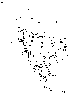
Fig. 6 is a front view of the tail lamp of the tail lamp structure for a
vehicle
according to the present invention, and Fig. 7 is a cross-sectional view taken
along a line 7-7 in Fig. 6.
The tail lamp 46 is a tail lamp employing a plurality of light-emitting diodes
(LED) 81... (...represents that there are plural number of components,
hereinafter) as the light sources, and includes a light-emitting diode board
82
shown in Fig. 7 for placing the light-emitting diodes 81..., the control
element
board 84 for placing a control element 83 for controlling the light-emitting
diodes 81..., an inner lens (diffuser panel) 85 shown in Fig. 7 for causing
light
from the light-emitting diodes 81... to diffuse, a light-shielding panel 86
disposed so as to be orthogonal to the inner lens 85 for blocking light from
the
light-emitting diodes 81..., a housing 87 for collectively storing the light-
emitting diode board 82, the control element board 84, the inner lens 85, and
WH 12783/cs
CA 02522371 2005-10-05
-10-
the light-shielding panel 86, a lens 88 for covering the housing 87, a harness
(wiring member) 89 extending from the housing 87.
The control element 83 is a generic designation including passive elements
such as resistance and capacitor, and positive elements such as transistor,
FET, IC.
Fig. 8 is a front view showing the light-emitting diode board and the housing
of the tail lamp structure for a vehicle according to the present invention,
and
illustrates that the light-emitting diode board 82 includes a plurality of
terminal plates (metal plates) 91-96 arranged in and fixed to the housing 87,
two light-emitting diodes 81, 81 are connected between the terminal plate 91
and the terminal plate 92, and two light-emitting diodes 81, 81 are connected
between the terminal plate 92 and a terminal plate 93, and two light-emitting
diodes 81, 81 are connected between the terminal plate 93 and the terminal
plate 94, and two light-emitting diodes 81, 81 are connected between the
terminal plate 94 and the terminal plate 95 and two light-emitting diodes 81,
81 are connected between the terminal plate 95 and a terminal plate 96, and
two light-emitting diodes 81, 81 are connected between the terminal plate 96
and the terminal plate 91.
The housing 87 includes fixing holes 98, 98 for fixing the inner fender 64,
and
the control element board 84 is provided with an internal wiring member 99
to be connected with the harness 89.
Fig. 9 is a back view of the tail lamp of the tail lamp structure for a
vehicle
according to the present invention, in which the harness 89 is extended
outward from the side of the housing 87, and branched into a power source
supply harness 102 and a signal harness 103 from a midpoint of an extended
harness 101. The power source supply harness 102 is provided with a coupler
104 at a distal end, and first to third connectors 105-107 at a distal end of
the
signal harness 103. In the drawing, reference numeral 108 designates a
harness draw-out member.
In other words, the tail lamp structure 60 (tail lamp 46) shown in Fig. 2 is
referable to be a structure in which the harness 89 is connected to the
control
WH 12783/cs
CA 02522371 2005-10-05
-11-
element board 84 (see Fig. 6), and the harness 89 is extended outward from
the side of the housing 87.
By connecting the harness 89 to the control element board 84, and causing the
harness 89 to be extended outward from the side of the housing 87, the depth
of the tail lamp 46 can be reduced, for example, in comparison with the case
in which the harness is extended rearward. Consequently, the sufficient
space can be secured with respect to the rear wheel 35 (see Fig. 2).
The harness draw-out member 108 is inclined along the inner fender 64, and
is arranged forwardly of the light-emitting diode board 82 and rearwardly of
the control element board 84.
Fig. 10 is a side view of the tail lamp of the tail lamp structure for a
vehicle
according to the present invention, in which the lens 88 is a member formed
of transparent resin, and includes an upper cover portion 111 for covering the
upper portion of the light-emitting diode board 82 (see Fig. 2), a lens body
portion 112 for allowing light from the light-emitting diodes 81... to
transmit
through the inner lens (diffuser panel) 85, and a lower cover portion 113 for
covering the control element board.
Therefore, as shown in Fig. 2, the tail lamp structure 60 is configured to
cause
the lens body portion 112 to project outward by covering the upper cover
portion 111 by the rear fender 43, and covering the lower cover portion 112 by
the mud guard cover 47.
Fig. 11 is a cross-sectional view taken along a line 11-11 in Fig. 6, showing
a
side cross-section of the tail lamp structure 60. In the motorcycle (vehicle)
10
shown in Fig. 1 including the rear fender 43 covering over the upper portion
of the rear wheel 35 (see Fig. 2), the mud guard cover 47 covering over the
rear portion of the rear wheel 35, the tail lamp structure 60 is referable to
be
such that the tail lamp 46 arranged around the rear fender 43 and the mud
guard cover 47, the tail lamp 46 being a tail lamp having light-emitting
diodes
81... as the light sources, and the tail lamp is referable to be composed of
the
light-emitting diode board 82 for placing the light-emitting diodes 81...
thereon, the control element board 84 for placing the control element 83 (see
Fig. 6) for controlling the light-emitting diodes 81... thereon, the housing
87
WH 12783/cs
CA 02522371 2005-10-05
-12-
for collectively accommodating the light-emitting diode board 82 and the
control element board 84, and the lens 88 for covering the housing 87, and to
be such that the control element board 84 is arranged downwardly of the
light-emitting diode board 82.
For example, it is preferable if the depth of the tail lamp of the vehicle can
be
reduced, because the entire length of the vehicle can be reduced, and a space
with respect to the rear wheel can be secured sufficiently.
In other words, by arranging the control element board 84 downwardly of the
light-emitting diode board 82, the depth of the tail lamp 46 is set to be
thin.
Consequently, the entire length of the motorcycle 10 (see Fig. 1) can be
reduced. Alternatively, the sufficient space with respect to the rear wheel 35
can be secured.
In the drawing, reference numeral 115... designates mounting screws for
mounting the light-emitting diode board 82 to the housing 87, reference
numeral 116 designates a mounting screw for mounting the control element
board 84 to the housing 87, and reference numeral 117 designates a mounting
screw for mounting the inner lens (diffuser panel) 85 to the lens 88.
In the drawing, reference numeral 128 designates an outer lens portion,
reference numeral 129 designates an inner lens portion, and the lens body
portion 112 is formed to have a two-layer structure. By disposing the clear
outer lens portion 128 on the outer side and the inner lens portion 129 having
a fine cut on the inner side, the clear tail lamp 46 providing depth feel can
be
realized and, since the light-emitting diodes (LED) 81... cannot be seen from
the outside, difference between ON and OFF can easily be recognized.
Also, by arranging the control element board 84 rearwardly of the light-
emitting diode board 82 with respect to the vehicle body, the depth of the
tail
lamp 46 can be reduced. Also, maintenanceability of the tail lamp 46 can be
improved.
Fig. 12 is a cross-sectional view taken along a line 12-12 in Fig. 6, and the
tail
lamp structure 60 is referable to be such that by arranging the control
element
board 84 downwardly of the light-emitting diode board 82, and covering the
WH 12783/cs
CA 02522371 2005-10-05
-13-
mud guard cover 47 on the lower portion of the lens 88, the control element
board 84 is masked so as not to be viewed from the outside.
With the arrangement of the control element board 84 is arranged
downwardly of the light-emitting diode board 82, and covering the lower
portion of the lens 88 with the mud guard cover 47, by masking the control
element board 84 so as not to be viewed from the outside, the control element
board 84 can be hidden from the eye when viewed from the outside, and can
be protected from the outside.
For example, the number of components can be reduced in comparison with
the case in which the control element board is masked using an additional
part. Alternatively, the existing part can be used conveniently, and the
application of the existing part (mud guard cover 47) can be increased.
By inclining the light-emitting diode board 82 and the control element board
84 along the inner fender 64, and arranging the same not in the same level
(arranged in two steps by differentiating the depth), a vacant space can be
effectively used, and accordingly, the tail lamp 46 can be formed compactly.
20 Consequently, the layout of the tail lamp 46 is facilitated.
It is also referable to be such that the light-emitting diode board 82 is
arranged not in the same level as the control element board 84, and the
control element board 84 is arranged downwardly of the light-emitting diode
25 board.
The tail Iamp structure 60 is referable to be such that the upper portion of
the
lens 88 (upper cover portion 111) is covered by the rear fender 43 and, by
covering the upper portion of the lens 88 with the rear fender 43, light
entering the tail lamp 46 from the outside can be blocked. Consequently, the
tail lamp for a vehicle with a good visibility can be realized.
In the drawing, reference numeral 118 designates a mounting screw for
tightening the inner lens (diffuser panel) 85 and the light-shielding panel 86
together, and reference numeral 119 designates a mounting screw for
mounting the inner fender 64 to the housing 87.
WH 22783/cs
CA 02522371 2005-10-05
-14-
By providing the inner lens 85 is provided between the light emitting diodes
81... and the lens 88, and providing the control element board 84 rearwardly
of the inner lens 85 with respect to the vehicle body, the depth of the tail
lamp
46 can be reduced. Also, the improvement of the maintenanceability of the
tail lamp 46 is achieved.
Furthermore, by providing the light-shielding panel 86 between the inner lens
85 and the control element board 84, light leaked on the side of the control
element board 84 can be blocked, and the designing property can be
improved. Then, since the light-shielding panel 86 is provided integrally
with the inner lens 85 (integrally mounted, or fastened with the mounting
screw 118 together), the assembleability can be improved.
While the tail lamp structure for a vehicle according to the present invention
is applied to the motorcycle as the vehicle as shown in Fig. 4, it is not
limited
thereto, and the vehicle may be two-wheelers, three-wheelers, or four-
wheelers.
While the tail lamp structure for a vehicle according to the present invention
includes the license lamp 44 on the welled portion as shown in Fig. 2, it is
not
limited thereto, and the number plate mounting portion may be provided on
the swelled portion.
While the tail lamp structure for a vehicle according to the present invention
includes the control element board 84 arranged downwardly of the light-
emitting diode board 82 as shown in Fig. 11, it is not limited thereto, and
the
control element board 84 may be arranged above the light-emitting diode
board.
While the tail lamp structure for a vehicle according to the present invention
includes the harness 89 connected to the control element board 84 via the
internal wiring member 99 as shown in Fig. 8, it is not limited thereto, and
the
harness may be connected to the light-emitting diode board.
According to the present invention, since the tail lamp includes the light-
emitting diode board for placing the light-emitting diode thereon, the control
element board for placing the control element for controlling the light-
WH 12783/cs
CA 02522371 2005-10-05
-15-
emitting diode thereon, the housing for collectively accommodating the light-
emitting diode board and the control element board, and the lens for covering
the housing, and the control element board is arranged upwardly or
downwardly of the light-emitting diode board, the depth of the tail lamp can
be set to a reduced value. Consequently, the entire length of the vehicle can
advantageously be reduced. Alternatively, the sufficient space is
advantageously secured with respect to the rear wheel.
According to an embodiment of the invention, since the control element
board is disposed downwardly of the light-emitting diode board, and the
control element board is covered by the mud guard cover, so that the control
element board is hidden from the eye when viewed from the outside, the
control element board can be hidden from the outside and can be protected
from the outside.
For example, in comparison with the case in which the control element board
is covered using an additional part, the number of components can
advantageously be reduced. Also, an existing part can be used conveniently,
and the application of the existing part can advantageously be increased.
According to another embodiment of the invention, since the harness is
connected to the control element board and the harness is extended from the
side of the housing toward the outside, for example, in comparison with the
case in which the harness is extended rearward, the depth of the tail lamp can
be reduced. Consequently, the sufficient space is advantageously secured
with respect to the rear wheel.
According to another embodiment of the invention, since the rear fender
extends above the lens rearward with respect to the upper portion of the lens,
light from the outside coming into the tail Iamp is blocked. Consequently, the
tail lamp for a vehicle having good visibility can advantageously be realized.
According to another embodiment of the invention, since the mud guard
cover is formed with the swelled portion, and the control element board is
hidden from the eye when viewed from the rear by the swelled portion, the
tail lamp of the vehicle can be arranged at a position shifted rearward.
WH 12783/cs
CA 02522371 2005-10-05
-16-
Consequently, the sufficient space is advantageously secured with respect to
the rear wheel.
According to another embodiment of the invention, since the swelled portion
is provided with the license lamp or the number plate mounting portion, the
flexibility of the design is advantageously increased.
According to another embodiment of the invention, since the inner lens is
provided between the light-emitting diode and the lens, and the control
element board is provided rearwardly of the inner lens with respect to the
vehicle body, the further reduction of the depth of the tail lamp is
advantageously achieved.
According to another embodiment of the invention, since the light-shielding
panel is provided between the inner lens and the control element board, light
leaked on the side of the control element board can advantageously be
blocked, and the designing property can be improved.
According to another embodiment of the invention, since the light-shielding
panel is provided integrally with the inner lens, the assembleability can be
improved.
According to another embodiment of the invention, since the tail lamp
includes the light-emitting diode board for placing the light-emitting diode
thereon, the control element board for placing the control element for
controlling the light-emitting diode thereon, the housing for collectively
accommodating the light-emitting diode board and the control element
board, and the lens for covering the housing, and the control element board is
arranged rearwardly of the light-emitting diode board with respect to the
vehicle body, the depth of the tail lamp can be reduced.
The tail lamp structure for a vehicle according to the present invention is
suitable for a large motorcycle Although various preferred embodiments of
the present invention have been described herein in detail, it will be
3~ appreciated by those skilled in the art, that variations may be made
thereto
without departing from the spirit of the invention or the scope of the
appended claims.
1NH 12783/cs