Language selection

Search

Patent 2522965 Summary

Third-party information liability

Some of the information on this Web page has been provided by external sources. The Government of Canada is not responsible for the accuracy, reliability or currency of the information supplied by external sources. Users wishing to rely upon this information should consult directly with the source of the information. Content provided by external sources is not subject to official languages, privacy and accessibility requirements.

Claims and Abstract availability

Any discrepancies in the text and image of the Claims and Abstract are due to differing posting times. Text of the Claims and Abstract are posted:

  • At the time the application is open to public inspection;
  • At the time of issue of the patent (grant).
(12) Patent: (11) CA 2522965
(54) English Title: HAIR IRON HAVING BUFFER MEMBER
(54) French Title: FER A CHEVEUX AVEC ELEMENT TAMPON
Status: Granted and Issued
Bibliographic Data
(51) International Patent Classification (IPC):
  • A45D 01/04 (2006.01)
  • A45D 01/06 (2006.01)
(72) Inventors :
  • CHOI, YOUNG-BUM (Republic of Korea)
(73) Owners :
  • VODANA CO., LTD.
(71) Applicants :
  • VODANA CO., LTD. (Republic of Korea)
(74) Agent: MBM INTELLECTUAL PROPERTY AGENCY
(74) Associate agent:
(45) Issued: 2012-02-07
(22) Filed Date: 2005-10-07
(41) Open to Public Inspection: 2006-09-02
Examination requested: 2005-10-07
Availability of licence: N/A
Dedicated to the Public: N/A
(25) Language of filing: English

Patent Cooperation Treaty (PCT): No

(30) Application Priority Data:
Application No. Country/Territory Date
10-2005-0017244 (Republic of Korea) 2005-03-02

Abstracts

English Abstract

The present invention relates to a hair iron having a buffer member, particularly to a hair iron having a buffer member, which is located in between two opposing steel plates to help hair passing through the steel plates to be straightened smoothly and prevent thermal deformation of hair. The invention is characterized by a hair iron comprising a first pressing member 10 and a second pressing member 20 to which steel plates 12, 22 having built-in thermal wire heaters 13, 23 are attached, respectively. A buffer member 40 is attached to the steel plate 22 which is attached to the second pressing member 20.


French Abstract

La présente invention concerne un fer à cheveux muni d'un élément tampon, en particulier un fer à cheveux muni dudit élément tampon qui est placé entre deux plaques d'acier opposées pour que les cheveux qui passent à travers les plaques d'acier soient redressés de manière lisse et afin d'empêcher toute déformation thermique des cheveux. L'invention se caractérise par un fer à cheveux muni d'un premier élément de pressage (10) et un second élément de pressage (20) auxquels sont fixés, respectivement, des plaques d'acier (12, 22) comportant des réchauffeurs de fils thermiques intégrés (13, 23). Un élément tampon (40) est fixé à la plaque d'acier (22) qui, elle est fixée au second élément de pressage (20).

Claims

Note: Claims are shown in the official language in which they were submitted.

THE EMBODIMENTS OF THE INVENTION IN WHICH AN EXCLUSIVE
PROPERTY OR PRIVILEGE IS CLAIMED ARE DEFINED AS FOLLOWS:
1. A hair iron comprising a first pressing member (10) and a second pressing
member
(20) having steel plates (12, 22), in which thermal wire heaters (13, 23) are
built in,
respectively, wherein a buffer member (40) is attached to the steel plate (22)
attached to
the second pressing member (20) and is made of an elastic material, and
wherein a
groove (22a), including a lower portion having a first width and an upper
portion having
a second narrower width, is formed on the steel plate (22), to which the
buffer member
(40) is attached, and the buffer member (40) includes a projecting part (40a)
extending
from a bottom surface thereof, wherein the projecting part (40a) of the buffer
member
(40) mechanically couples the buffer member (40) in the groove (22a).
2. The hair iron of claim 1, wherein the buffer member (40) is made of heat-
resistant
silicone.
3. The hair iron of claim 1, wherein the buffer member (40) is made of
urethane rubber.
4. A hair iron comprising:
a first pressing member;
a second pressing member disposed opposite the first pressing member;
a first steel plate disposed on the first pressing member;
a second steel plate disposed on the second pressing member;
6

a groove formed in the first steel plate disposed on the first pressing
member, the groove
including a lower portion having a first width and an upper portion having a
second width
narrower than the first width; and
a heat resistant elastic buffer member substantially filling the groove,
wherein the heat
resistant elastic buffer member includes a first lower portion having a width
substantially
equal to the first width of the groove, and a second upper portion having a
width
substantially equal to the second width of the groove.
5. The hair iron of claim 1, further comprising a coating disposed on a
surface of the steel
plates, the coating selected from the group consisting of: an anodized
coating, a ceramic
coating, a polytetrafluoroethylene coating, a perfluoroalkoxy coating, and a
fluorinated
ethylene propylene coating.
6. The hair iron of claim 4, further comprising a coating disposed on a
surface of the first
steel plate, the coating selected from the group consisting of: an anodized
coating, a
ceramic coating, a polytetrafluoroethylene coating, a perfluoroalkoxy coating,
and a
fluorinated ethylene propylene coating.
7. The hair iron of claim 1, wherein the buffer member is only attached to the
steel plate
attached to the second pressing member.
6a

Description

Note: Descriptions are shown in the official language in which they were submitted.


CA 02522965 2005-10-07
HAIR IRON HAVING BUFFER MEMBER
BACKGROUND OF THE INVENTION
1. Field of the Invention
The present invention relates to a hair iron having a buffer member,
particularly to a
hair iron having a buffer member, which is located in between two opposing
steel plates to
help hair between the steel plates to be straightened smoothly and prevent
thermal
deformation of hair.
2. Description of the Related Art
A hair iron is an apparatus used to straighten or roll hair at home or beauty
salons.
FIG. 1 is a drawing showing the conventional hair iron. It is manufactured by
inserting
thermal wire heaters 13b into two opposing steel plates 12b. When the steel
plates 12b are
heated by the thermal wire heaters, you can straighten or roll your hair by
applying pressure
from outside of the external case 11 a. Such a conventional hair iron is
driven by a power
supply. Descriptions on the power supply, including electric wires and the
temperature
controller 70, will be omitted here.
A first pressing member 1 and a second pressing member 2 are joined by a hinge
5.
To the first pressing member I is fixed a spacing stick 60. The spacing stick
60 has a
projecting part 61 at the end. The second pressing member 2 has a spacing
member 62,
which allows the spacing stick 60 to move up and down. Thus, the spacing
between the first
pressing member and the second pressing member can be adjusted by pressing
with fingers.
At the bottom of the spacing member 62 is mounted a spring 63.
In the conventional hair roller, the steel plates 12b touch with each other,
so that it
la

CA 02522965 2005-10-07
does not fix hair smoothly. Also, hair may be damaged because of the heated
steel
plates.
SUMMARY OF THE INVENTION
It is an object of the present invention to provide a hair iron having a
buffer member,
which is located in between two opposing steel plates to help hair between the
steel plates to
be straightened smoothly and prevent thermal deformation of hair.
To attain the object, the present invention provides a hair iron comprising a
first
pressing member 10 and a second pressing member 20 having steel plates 12, 22,
in which
thermal wire heaters 13, 23 are built in, respectively, wherein a buffer
member 40 is attached
to the steel plate 22 attached to the second pressing member 20.
BRIEF DESCRIPTION OF THE DRAWINGS
FIG. 1 shows the conventional hair iron.
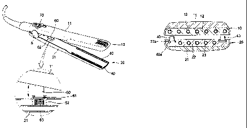
FIG. 2 shows the hair iron of the present invention, which is laid open.
FIG. 3 shows the hair iron of the present invention, which is shut.
FIG. 4 shows the cross-section of the hair iron of the present invention.
FIG. 5 shows the second pressing member of the hair iron of the present
invention.
DETAILED DESCRIPTION OF THE INVENTION
Hereunder the invention is described in more detail, referring to the attached
drawings.
FIG. 2 shows the hair iron of the present invention, which is laid open. FIG.
3
shows the hair iron of the present invention, which is shut. FIG. 4 shows the
cross-section
of the hair iron of the present invention. And, FIG. 5 shows another
embodiment of the hair
2

CA 02522965 2009-03-16
iron of the present invention. The present invention is characterized by a
hair iron
comprising a first pressing member 10 and a second pressing member 20 having
steel plates
12, 22, in which thermal wire heaters 13, 23 are built in, respectively,
wherein a buffer
member 40 is attached to the steel plate 22 attached to the second pressing
member 20.
The buffer member 40 is made of heat-resistant materials such as heat-
resistant
silicon, silver, TeflonTM or urethane rubber. The buffer member 40 may be
either attached
on the surface of the steel plate 22 or inserted in a groove 22a formed on the
surface of the
steel plate 22. Although not shown in the drawings, the buffer member 40 may
be attached
on each surface of the two steel plates 12, 22 of the first and second
pressing members 10, 20.
In addition to heat-resistant silicon, the buffer member 40 may be made of any
material that
is elastic and heat resistant.
External cases 11, 21 are attached to outside of the steel plates 12, 22,
respectively.
Each end of the first and second pressing members 10, 20 may open and shut by
a hinge 5.
A spacing stick 60 is fixed to the first pressing member 10. The spacing stick
60 has a
projecting part 61 at the end. The second pressing member 20 has a spacing
member 62,
which allows the spacing stick 60 to move up and down. The spacing between the
first
pressing member 10 and the second pressing member 20 can be adjusted by
pressing outside
of the first and second pressing members with fingers. At the bottom of the
spacing
member 62 is mounted a spring 63.
On the steel plate 22 to which the buffer member 40 is attached, a groove 22a
is
formed along the steel plate 22. Heat-resistant silicon is inserted into the
groove 22a as the
buffer member 40. The buffer member 40 has a projecting part 40a which
prevents the
buffer member 40 from being detached from the groove 22a. That is, the
projecting part 40a
is inserted into the groove 22a, and thus the buffer member 40 is not
detached.
Like other conventional hair irons, the hair iron of the present invention has
a
3

CA 02522965 2009-03-16
temperature controller 70, power supply wires, etc. as a means of controlling
temperature.
Detailed description thereabout is omitted, because it is well known in the
related art.
On the surface of the steel plates 12, 22 is formed a ceramic coating,
TeflonTM
coating or anodizing coating. The heat-resistant silicon used in the invention
can endure up
to 100-230 C.
Hereunder is given a description of how to straighten or roll hair using the
hair iron
of the present invention.
First, plug in the power supply to heat the steel plates 12, 22. While the
steel plates
12, 22 are heated, the temperature controller 70 maintains the temperature
adequately.
Then, locate hair in between the opposing fist and second pressing members 10,
20
and smoothly pool the hair iron while pressing the outside of the first and
second pressing
members with hand. At this point, hair is pressed in between the steel plate
12 and the
buffer member 40 and heat is transferred to the hair. Because the buffer
member 40 is made
of heat-resistant silicon, it is heat resistant and elastic. Thus, the hair
can be effectively
pressed. Consequently, hair can be straightened or rolled.
Hair located between the buffer member 40, which is attached on the steel
plate 22 of
the second pressing member 20, and the steel plate 12 is pressed well and
glides smoothly,
because the heat-resistant silicon is soft. Also, because the heat-resistant
silicon is elastic,
there will be no space between the buffer member 40 and the steel plate 22.
Also, because
the heat-resistant silicon is located between the metallic steel plates 12,
22, damage done to
hair by heat can be reduced. The buffer member 40 may be replaced with a new
one after
prolonged use.
The hair iron of the present invention has a buffer member made of heat-
resistant
silicon, which blocks direct contact of steel plates 12, 22. The buffer member
holds hair
smoothly and removes space between the steel plates. Also, hair damage can be
prevented.
4

CA 02522965 2005-10-07
Hair located between the buffer member 40, which is attached on the steel
plate 22 of the
second pressing member 20, and the steel plate 12 is pressed well and glides
smoothly,
because the heat-resistant silicon is soft. Also, because the heat-resistant
silicon is elastic,
there will be no space between the buffer member 40 and the steel plate 22.
Also, because
the heat-resistant silicon is located between the metallic steel plates 12,
22, damage done to
hair by heat can be reduced.
The buffer member of the present invention prevents hair form being pulled off
and
makes hair straightening or rolling more pleasant when using a hair iron.
While the present invention has been described in detail with reference to the
preferred
embodiments, those skilled in the art will appreciate that various
modifications and
substitutions can be made thereto without departing from the spirit and scope
of the present
invention as set forth in the appended claims.
5

Representative Drawing
A single figure which represents the drawing illustrating the invention.
Administrative Status

2024-08-01:As part of the Next Generation Patents (NGP) transition, the Canadian Patents Database (CPD) now contains a more detailed Event History, which replicates the Event Log of our new back-office solution.

Please note that "Inactive:" events refers to events no longer in use in our new back-office solution.

For a clearer understanding of the status of the application/patent presented on this page, the site Disclaimer , as well as the definitions for Patent , Event History , Maintenance Fee  and Payment History  should be consulted.

Event History

Description Date
Maintenance Request Received 2024-10-03
Maintenance Fee Payment Determined Compliant 2024-10-03
Letter Sent 2024-04-11
Inactive: Single transfer 2024-04-09
Inactive: Recording certificate (Transfer) 2022-11-17
Inactive: Single transfer 2022-10-05
Change of Address or Method of Correspondence Request Received 2020-05-08
Common Representative Appointed 2019-10-30
Grant by Issuance 2012-02-07
Inactive: Cover page published 2012-02-06
Pre-grant 2011-11-24
Inactive: Final fee received 2011-11-24
Letter Sent 2011-08-08
Notice of Allowance is Issued 2011-08-08
Inactive: Approved for allowance (AFA) 2011-07-27
Amendment Received - Voluntary Amendment 2011-02-16
Inactive: S.30(2) Rules - Examiner requisition 2010-08-20
Amendment Received - Voluntary Amendment 2010-02-26
Inactive: S.30(2) Rules - Examiner requisition 2009-08-27
Amendment Received - Voluntary Amendment 2009-03-16
Inactive: S.30(2) Rules - Examiner requisition 2008-09-16
Small Entity Declaration Determined Compliant 2007-09-13
Application Published (Open to Public Inspection) 2006-09-02
Inactive: Cover page published 2006-09-01
Inactive: IPC assigned 2006-05-05
Inactive: First IPC assigned 2006-05-05
Inactive: Filing certificate - RFE (English) 2005-11-25
Application Received - Regular National 2005-11-22
Letter Sent 2005-11-22
All Requirements for Examination Determined Compliant 2005-10-07
Request for Examination Requirements Determined Compliant 2005-10-07

Abandonment History

There is no abandonment history.

Maintenance Fee

The last payment was received on 2011-10-05

Note : If the full payment has not been received on or before the date indicated, a further fee may be required which may be one of the following

  • the reinstatement fee;
  • the late payment fee; or
  • additional fee to reverse deemed expiry.

Patent fees are adjusted on the 1st of January every year. The amounts above are the current amounts if received by December 31 of the current year.
Please refer to the CIPO Patent Fees web page to see all current fee amounts.

Owners on Record

Note: Records showing the ownership history in alphabetical order.

Current Owners on Record
VODANA CO., LTD.
Past Owners on Record
YOUNG-BUM CHOI
Past Owners that do not appear in the "Owners on Record" listing will appear in other documentation within the application.
Documents

To view selected files, please enter reCAPTCHA code :


To view images, click a link in the Document Description column. To download the documents, select one or more checkboxes in the first column and then click the "Download Selected in PDF format (Zip Archive)" or the "Download Selected as Single PDF" button.

List of published and non-published patent-specific documents on the CPD .

If you have any difficulty accessing content, you can call the Client Service Centre at 1-866-997-1936 or send them an e-mail at CIPO Client Service Centre.


Document
Description 
Date
(yyyy-mm-dd) 
Number of pages   Size of Image (KB) 
Abstract 2005-10-06 1 14
Drawings 2005-10-06 3 47
Claims 2005-10-06 1 24
Description 2005-10-06 5 173
Representative drawing 2006-08-07 1 8
Representative drawing 2008-11-04 1 10
Description 2009-03-15 5 177
Claims 2009-03-15 2 56
Drawings 2009-03-15 3 49
Claims 2011-02-15 2 60
Representative drawing 2012-01-12 1 14
Confirmation of electronic submission 2024-10-02 1 62
Acknowledgement of Request for Examination 2005-11-21 1 176
Filing Certificate (English) 2005-11-24 1 158
Reminder of maintenance fee due 2007-06-10 1 112
Commissioner's Notice - Application Found Allowable 2011-08-07 1 163
Courtesy - Certificate of Recordal (Change of Name) 2024-04-10 1 406
Courtesy - Certificate of Recordal (Transfer) 2022-11-16 1 400
Fees 2011-10-04 1 156
Correspondence 2007-09-12 2 69
Fees 2007-09-24 1 55
Fees 2008-10-06 1 45
Fees 2010-09-28 1 201
Correspondence 2011-11-23 2 60
Maintenance fee payment 2017-09-14 1 26