Note: Descriptions are shown in the official language in which they were submitted.
CA 02523104 2005-10-20
WO 2004/097346 PCT/SE2003/002064
A METHOD FOR MONITORING THE STAY TIME IN A RESTRICTED CONDUIT
TECHNICAL FIELD
The present invention relates to a method for monitoring the stay time in a
restricted
conduit where a first measurement registration takes place at the beginning of
the restricted
. r
conduit and a second measurement registration takes place at the end of the
restricted conduit.
BACKGROUND ART
In the heat treatment of pumpable liquid food products, the product is heated
to a
to predetermined temperature. The temperature depends on the type of process
that is intended,
such as, for example, pasteurisation or sterilisation. When the product has
reached the desired
temperature, it is to be kept at this temperature for a given, predetermined
interval of time. By
combining temperature with stay time for different products, there will be
obtained products
with different shelf lives, such as sterile products that can be delivered at
room temperature
and such products as are to be delivered in an unbroken refrigeration chain.
The heat treatment may be put into effect indirectly or directly. In indirect
heat
treatment, the heating takes place in some form of heat exchanger, for example
a plate heat
exchanger or a tube heat exchanger. In the direct methods, steam is supplied
direct to the
product. Examples of direct methods are injection heating and infusion
heating.
2o In order to be able to maintain the temperature which the product obtains
as a result of
the heat treatment during a given predetermined interval of time, use is made
of a holding
tube which is placed in immediate association with the heat treatment
equipment. The holding
tube is normally designed as a pipe loop, or alternatively a straight pipe
length, or as a
combination of both. The length of the pipe or the pipe loop corresponds to
the time which for
a given product at a given calculated capacity stays in the holding tube. It
is important that the
stay time be exact, since too short a stay time does not give the desired
treatment of the
product, with the result that a product is obtained which does not have the
intended shelf life
and which may rapidly become a downright health hazard. Excessively long stay
times can
destroy the product which, as a result of excessive thermal shock, suffers
from changes in
flavour, aroma or nutrient content.
Normally, temperature indicators are provided in holding tubes, the indicators
being
placed ahead of and after the holding tube, where the temperature indicator
placed ahead of
the holding tube is included in the control of the regulator loop for the heat
treatment
equipment. The temperature indicator placed after the holding tube is used to
monitor that the
1
CA 02523104 2005-10-20
WO 2004/097346 PCT/SE2003/002064
product was at the correct temperature in the holding tube. On the other hand,
at present there
are few reliable methods of checking that the stay time is that intended.
The traditional methods that consist of the conductivity method and the dye
method
cannot be employed during production. The product must then be replaced by
water and salt
or a dye, respectively, is added to the water. Thereafter, the time. it takes
for the saline
solution or the dyed watery respectively, to pass through the holding tube is
measured. The
saline water is registered by conductivity measurements and the dyed water is
registered by
means of observation. Both of these methods suffer from numerous drawbacks and
the error
sources are obvious.
1o Patent Specification WO 01/98738 discloses a method of monitoring the stay
time in a
restricted pipe length by inducing a temperature change in the product. This
temperature
change is registered by one temperature gauge ahead of the holding tube and
one temperature
gauge after the holding tube. The time which elapses between these
registrations constitutes
the stay time. The drawbacks inherent in this method are that it is necessary
to induce a
disruption which is sufficiently great for it to be able to be measured in a
single measurement.
There is always a danger in disrupting a process and a wealth of knowledge is
required to be
able to carry this out reliably.
OBJECTS OF THE INVENTION
2o One object of the present invention is to realise a method for monitoring
and
monitoring the stay time in which use is made of natural temperature
variations in the product
so that it is not necessary to intervene and disrupt the process.
A further object of the present invention is that the method may be employed
continuously or intermittently so as to obtain a more reliable monitoring of
the stay time than
in prior art methods.
SOLUTION
These and other objects have been attained according to the-present invention
in that
the method of the type described by way of introduction has been given the
characterising
3o features that the first measurement registration x measures a chemical or
physical magnitude
and the second measurement registration y measures the same chemical or
physical
magnitude, and where a best co-variation between x and y is sought, and that a
time lag ~ at
the best co-variation gives the stay time.
2
CA 02523104 2005-10-20
WO 2004/097346 PCT/SE2003/002064
Preferred embodiments of the present invention have further been given the
characterising features as set forth in the appended subclaims.
BRIEF DESCRIPTION OF THE ACCOMPANYING DRAWINGS
One preferred embodiment of the present invention will now be described in
greater
detail hereinbelow, with reference to the accompanying Drawings. In the
accompanying
Drawings:
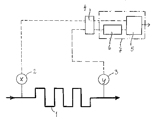
Fig. 1 shows a holding tube with equipment for carrying out the method;
Fig. 2 is a diagram showing continuous measurement registrations of x and y;
1o Fig. 3 is a diagram showing correlation calculations for a series of
measurement
values;
Fig. 4A is a diagram showing measurements under ideal conditions;
Fig. 4B is a diagram showing measurements with dispersion; and
Fig. 4C is a diagram showing measurements with filter.
DESCRIPTION OF PREFERRED EMBODIMENT
The method according to the present invention is employed to monitor the stay
time in
a restricted conduit. The restricted conduit may consist of a so-called
holding tube 1 as shown
in Fig. l, i.e. a restricted pipe length or pipe loop in which a product which
has been heat
2o treated is to stay during a given, predetermined interval of time. The
holding tube 1 is
normally placed in immediate association with heat treatment equipment which
may be a heat
exchanger, or alternatively an injector or an infusor (not shown on the
Drawings).
At the beginning of the restricted conduit, the holding tube 1, there is
disposed a first
temperature gauge 2, for example a thermoelement or a resistor element or some
other form
of sensor which displays sufficiently rapid registration. At the end of the
holding tube 1, there
is disposed a second temperature gauge 3, for example a thermoelement or a
resistor element
or some other form of sensor which displays sufficiently rapid registration.
The two
temperature gauges 2, 3 should be of the same type or have the same
performance.
If the intention is for a continuous monitoring of the stay time, it is
possible to utilise
3o the stationary temperature gauges 2, 3 that are normally provided in the
beginning and in the
end of a holding tube 1. These temperature gauges 2, 3 are normally employed
to check that
the temperature reaches the predetermined level. If the intention is for a
more temporary
checking of the stay time, use may be made of supplementary temperature gauges
2, 3 in
order not to unnecessarily disrupt the process.
3
CA 02523104 2005-10-20
WO 2004/097346 PCT/SE2003/002064
The temperature gauges 2, 3 are suitably disposed so that they measure the
temperature centrally in the pipe so as to obtain the highest level of
accuracy. The temperature
measurements are registered and processed in computer controlled process
monitoring
equipment. If the monitoring equipment does not have sufficient capacity, it
may possibly
need to be supplemented with a computer. As shown in Fig. 1, the measured
values enter into
a so-called logger 4. A logger 4 registers, with a certain preselected
interval, the measurement
values from the two temperature gauges 2, 3 and stores them. The measurement
values are
then used for calculations in a calculator unit 5 in a computer 7.
Alternatively, the logger 4
may constitute a part of a computer 7.
l0 Other physical or chemical magnitudes, such as conductivity, may be
measured as an
alternative to the temperature. However, the commonest procedure is
temperature
measurement.
In a product that has been heat treated and is thereafter to pass through a
holding tube
1, there are minor natural temperature variations or changes, like a natural
noise. If a first
measurement registration measures a physical or chemical magnitude x, a second
measurement registration measures the same physical or chemical magnitude y.
Fig. 2 is a
diagram showing continuous measurement registrations x and y. The vertical
axis of the
diagram shows the measurement result and the horizontal axis shows the time.
In the preferred embodiment, the first measurement registration consists of
the first
temperature gauge 2 and the second measurement registration of the second
temperature
gauge 3. The physical or chemical unit which is measured is the temperature.
The diagram
shows how the temperature quite naturally varies with time by minor changes.
Naturally,
disruptions may also be generated in the product, but it is an advantage if it
is possible to
avoid disrupting the process.
The two curves for x and y are offset in relation to one another. By
calculating the best
co-variations for the two curves, a time lag i will be obtained between the
two curves which
directly gives the stay time in the restricted conduit. The co-variation may
be described as
constituting the relationship between the variations in the measurements. The
relationship
between x and y is calculated in relation to the time lag and the best co-
variation is to be
found where the relationship is strongest. The co-variation calculations are
carried out in the
calculator unit 5 of the computer 7.
The best co-variation may be calculated in two ways. In the preferred
embodiment, a
correlation calculation p of x and y is made in accordance with the following
formula: pX,y =
4
CA 02523104 2005-10-20
WO 2004/097346 PCT/SE2003/002064
cov(x,y)/8X8y, where cov is a co-variance function of a measurement series of
a sufficient
number of the variables x and y, i.e. in the preferred embodiment the
temperatures. 8 is the
standard deviation for x and y, respectively.
A correlation function, such as that which is shown in Fig. 3, is a curve
showing the
correlation pas a function of the time lag i. The correlation function is
calculated according
to the formula: p(i) = cov(x, y(i)/8X8y, where y(~) is a measurement series of
y with the time
lag i in relation to x. The vertical axis of the diagram indicates the
correlation p and the
horizontal axis indicates the time lag i in seconds. In the diagram, a clear
maximum is seen
which lies close to a correlation of 1. Those maxima that can be employed so
as to give a
to good monitoring of the stay time may lie close to 1. The maxima of the
diagram occur at a
time lag i which is 20 seconds. The stay time for the product for which the
measurements and
calculations have been made is thus 20 seconds.
In the preferred embodiment, there will thus be obtained a stay time in a
restricted
conduit which is equal to the time lag i so that the correlation function p(i)
is maximised.
The best co-variation can alternatively be calculated with the least square
root method,
in order to fmd the smallest deviation between x and y. This calculation is
made according to
the formula: k(i) = E(x(t) - y(t+i))2/8X8Y, where k is the smallest square
total as a function of
the time lag i. 8 is the standard deviation for x and y, respectively. In the
alternative
embodiment, there will thus be obtained a stay time in a restricted conduit
which is equal to
2o the time lag i so that the smallest square root sum k(i) is minimised.
The above method may be employed for continuous measurements and calculations
and where the control equipment of the process can immediately issue an alert
if a desired
stay time is not attained. The above method may also be employed for quality
control in an
installation where a limited measurement series of the temperature
measurements x and y is
made in order to ensure that the stay time is that intended.
With a view to further refining the measurement method and by such means
obtaining
more exact measurement values, it is possible to compensate for the dispersion
that occurs in
the product to which the measurements refer. Dispersion entails that the
natural variation, for
example of the temperature, strives for a certain equalisation because of
turbulence, flow
profile and diffusion of different types. Figs. 4A-C show different
measurements of x and y
which, in these diagrams, are stated as being temperature. Other physical or
chemical
magnitudes can also be measured.
5
CA 02523104 2005-10-20
WO 2004/097346 PCT/SE2003/002064
In Fig. 4A, x and y are measured in ideal conditions and no dispersion occurs.
Thus,
the distance L indicates the stay time. In Fig. 4B, x and y have been measured
in natural
conditions, i.e. dispersion occurs and the curve for y has a more extended
appearance. Since
the best co-variation will be a mean value, the distance M constitutes the
calculated stay time.
The distance, L constitutes the stay time for those parts of the product which
stay in the
holding tube for the shortest time. Thus, L is the desired stay time.
By filtering the measurement and thereby recreating the natural disruption
without
dispersion, a diagram will be obtained in accordance with Fig. 4C. The
distance L indicters
the correct stay time, while the distance N constitutes the calculated mean
stay time. Since N
to lies considerably closer to the ideal value L than does M, there will be
obtained by filtration a
more exact value for the stay time than arnved at by calculations without
filtering. By
filtering, x is reconstnicted from the measurement for y and the dispersion is
thereby
discounted. An average stay time (= measurement volume/volume flow) can then
also be
calculated. The difference between L and N, i.e. how well x has been
reconstructed from y,
depends on how exact the filter is, the better the filter, the smaller the
difference. A filter unit
6 in the computer 7 is shown in Fig. 1, and while the measurement values x
from the first
temperature gauge 2 go direct to the calculator unit 5, the measurement values
y from the
second temperature gauge 3 pass the filter unit 6.
As will have been apparent from the above description, the present invention
realises a
method for monitoring the stay time in a restricted conduit where it is
possible to carry out the
monitoring continuously or intermittently. The method can be carned into
effect on product,
which gives a more reliable result than prior art methods. The method
according to the present
invention employs existing variations of, for example, the temperature in the
product, for
which reason it is not necessary to induce disruptions, thus affording a more
reliable method.
6