Note: Descriptions are shown in the official language in which they were submitted.
CA 02523123 2005-10-20
WO 2004/095718 PCT/US2004/012217
AUTOMATIC FREQUENCY CONTROL PROCESSING
IN MULTI-CHANNEL RECEIVERS
Field of the Invention
The present invention generally relates to the field of signal receivers, and
more particularly relates to the operation of automatic frequency control in
multiple
channel receivers.
Background of the Invention
Heterodyne radio frequency (RF) receivers are receivers that use one or more
internally generated RF signals, referred to as local oscillators (LO), to aid
in the
reception of a radio signal. The LO signals are generated at a fixed frequency
offset
relative to the radio frequency of the radio signal to be received. The LO
signal is
mixed with the received radio signal to produce an "Intermediate Frequency"
(IF) at
the offset of the LO from the received radio signal. Some heterodyne RF
receivers
use an IF frequency of zero so that the tuned RF frequency is down-converted
to a
baseband or DC centered signal. Processing performed at the zero frequency IF
is
referred to as baseband processing.
The frequency stability of the LO signal within a receiver sets the tuned RF
frequency accuracy of the receiver. LO signals are frequently generated with a
synthesized RF signal generation process. Synthesized RF signal generation
utilizes a
frequency reference generator to generate a frequency reference signal that is
-1-
CA 02523123 2005-10-20
WO 2004/095718 PCT/US2004/012217
generally at a relatively low frequency and a radio frequency signal is
derived from
this reference frequency signal by multiplying the reference frequency by a
specified
number. The output frequency of a synthesized RF signal generator can be
varied
during receiver operations by one of two techniques. The output frequency can
be
changed by reconfiguration of the signal derivation circuitry so that the
input signal
reference is multiplied by a different number. The output frequency of a
synthesized
RF signal generator can also be changed by varying the output frequency of the
reference generator. Reconfiguration of the signal generation circuitry
frequently
results in a period of output signal instability before the newly derived
output signal
becomes stable and usable as an LO within a stable RF receiver. Tracking an RF
frequency of a received signal is in many cases performed in a heterodyne
receiver by
changing the output frequency of the reference frequency oscillator driving
the
synthesized RF signal generator.
Some radio receivers are required to simultaneously receive multiple RF
signals. These receivers often share a common frequency reference generator
and use
multiple RF synthesizers to generate one or more LO signals for each received
signal.
Heterodyne RF receivers frequently track the frequency of the received RF
signal or signals. Frequency tracking of the received RF signal is performed
to
accommodate short and long term frequency instability of both the internally
generated LO signal and the RF signal that is being received. Traclung of the
received RF signal is typically performed by adjusting the frequency of the LO
signal
generator so as to properly track the received RF signal. In order to improve
-2-
CA 02523123 2005-10-20
WO 2004/095718 PCT/US2004/012217
reception during LO adjustments, radio receivers with synthesized LO
generators
sometimes traclc received signals by adjusting the frequency reference of the
LO
synthesizer. Radio receivers that receive multiple RF signals and that derive
multiple
LO signals from a single frequency reference are able to tracle only one
received RF
signal by adjustment of the frequency reference. A signal with a highly stable
RF
frequency is often chosen to be tracked by adjustment of the receiver's
frequency
reference. The other channels of these receivers typically traclc signals by
changing
the LO frequency by reconfiguration of the synthesized signal generator
producing
the LO signal. When the reference frequency of these receivers is adjusted to
track
one received signal, the other signals that are tracked by other channels of
the RF
receiver will be off-tuned from their tuned center frequency. If any other
channel
changes its tuned center frequency by more than the traclung bandwidth of that
channel, the tracl~ing of the received signal is lost. This requires this
other channel to
reacquire its RF signal, and often introduces periods of signal "drop-outs"
where data
communicated during this reacquisition is lost. Signals that require lengthy
reacquisition processing, such as GPS signals, can be lost for an appreciable
amount
of time and degrade the usefulness of the receiver.
Therefore a need exists to overcome the problems with the prior art as
discussed above.
-3-
CA 02523123 2005-10-20
WO 2004/095718 PCT/US2004/012217
Summary of the Invention
According to a preferred embodiment of the present invention, a multiple
channel receiver comprises a reference oscillator that produces a frequency
reference
signal and that further accepts a frequency adjustment. The receiver also
comprises a
first receiver, that is electrically coupled to the reference oscillator, and
that receives
at least a first transmitted signal that is transmitted at a first signal
frequency. The
first receiver tunes to a first tuned frequency based upon a first local
oscillator signal
that is derived from the frequency reference signal. The receiver also
comprises a
frequency reference adjustor, that is electrically coupled to the reference
oscillator,
and that produces the frequency adjustment. The receiver also comprises a
second
receiver, that is electrically coupled to the frequency reference adjustor,
and that
receives at least a second transmitted signal that is transmitted at a second
signal
frequency. The second receiver tunes to a second tuned frequency based upon a
second local oscillator signal that is derived from the frequency reference
signal. The
second receiver further accepts an indication of the frequency adjustment and
adjusts
a relationship between the frequency reference signal and the second local
oscillator
signal in response to the indication of the frequency adjustment.
According to a preferred embodiment of the present invention, a method for
receiving multiple signals comprises the steps of generating a frequency
reference
signal and tuning a first receiver to a first tuned frequency based upon a
first local
oscillator signal. The first local oscillator signal in this method is related
to the
frequency reference signal. This method then comprises tuning a second
receiver to a
-4-
CA 02523123 2005-10-20
WO 2004/095718 PCT/US2004/012217
second tuned frequency based upon a second local oscillator signal that is
also derived
from the frequency reference signal. The method then comprises commanding a
frequency adjustment of the frequency reference signal and commanding an
adjustment of a relationship between the frequency reference signal and the
second
local oscillator signal in response to the commanding of the frequency
adjustment.
Brief Description of the Drawings
FIG. 1 is a block diagram illustrating a mobile communications system
according to a preferred embodiment of the present invention.
FIG. 2 is a block diagram of a combined receiver according to a
preferred embodiment of the present invention.
FIG. 3 is a bloclc diagram of a reference oscillator according to a
preferred embodiment of the present invention.
FIG. 4 is a bloclc diagram of an NCO based local oscillator according
to a preferred embodiment of the present invention.
FIG. 5 is a block diagram of an NCO based local oscillator according
to another embodiment of the present invention.
FIG. 6 is a block diagram of a reference oscillator structure according
to another embodiment of the present invention.
FIG. 7 is a processing flow diagram illustrating the automatic
frequency control processing of a multiple channel receiver according to
preferred
embodiments of the present invention.
-5-
CA 02523123 2005-10-20
WO 2004/095718 PCT/US2004/012217
Detailed Description
The present invention, according to a preferred embodiment, overcomes
problems with the prior art by providing a multiple channel receiver that uses
a single
reference oscillator as a frequency reference signal generator for some or all
of the
local oscillators that are associated with the plurality of receiver channels
incorporated into the multiple channel receiver, and then using a signal
received by
one of the plurality of receiver channels to perform automatic frequency
control
(AFC) of the single frequency reference oscillator. A transmitted signal that
is
transmitted at an accurate RF signal frequency is chosen to be the signal that
is used
to perform AFC. The other receiver channels of this receiver also derive local
oscillator signals from the same frequency reference signal. The other
receiver
channels in the exemplary embodiments 'of the present invention are also
provided
with an indication of frequency adjustments that are applied to the reference
oscillator, so as to allow the local oscillators of those other receiver
channels to be
adjusted in order to accommodate the frequency shift that is to be applied to
the
frequency reference signal. This operation allows the other receiver channels
to
maintain their tuned frequency even when the frequency of the output of the
frequency reference oscillator is changed during AFC processing. Thus, the
frequency reference signal of the receiver can be maintained at an accurate
frequency
and the signal acquisition performance of receiver channels that are acquiring
new
signals is improved while minimizing the affect of frequency reference signal
-6-
CA 02523123 2005-10-20
WO 2004/095718 PCT/US2004/012217
adjustments on receiver channels that are receiving and tracking transmitted
signals.
This is of particular advantage in multiple channel receivers that are used to
receive
spread spectrum signals, such as GPS signal transmissions, since these signals
frequently have extended acquisition processing that can be greatly aided by
an
accurate frequency reference. Providing the other receiver channels with an
indication of frequency adjustments that are applied to the frequency
reference signal
allows receiver channels that are tracl~ing signals to maintain their
tracl~ing of the
received signal during the shift in the frequency of the output of the
frequency
reference oscillator caused by AFC operations and reduces or eliminates the
loss of
data when the frequency reference signal is adjusted.
The features and advantages of the present invention are described by
reference to an exemplary embodiment of the present invention that is
incorporated
into a handheld radio communications transceiver that also includes an
internal GPS
receiver. An exemplary mobile communications system 100 that uses such a
handheld radio communications transceiver is illustrated in FIG. 1. The
exemplary
mobile communications system 100 is shown to include a terrestrial
communications
base station 108 that has a base antenna 106, a base communications
transceiver 102
and a base station GPS receiver 104. The base station GPS receiver 104 of this
exemplary embodiment processes signals from the Global Positioning System
(GPS)
so as to derive highly accurate time and position references. The GPS receiver
provides a highly stable base station frequency reference signal 114 to the
base
communications transceiver 102. Other embodiments of the base station 108,
such as
CA 02523123 2005-10-20
WO 2004/095718 PCT/US2004/012217
in GSM systems, utilize a rubidium oscillator as a frequency standard, instead
of the
base GPS receiver 104. The base communications transceiver 102 uses this base
station frequency reference signal 114 to derive transmitted RF signals that
are
communicated over the wireless link 112. The base communications transceiver
102
of the exemplary embodiment is able to produce a transmitted signal with an RF
signal frequency accuracy on the order of +l- 0.2 ppm due to the accuracy of
the GPS
derived frequency reference signal 114. The base antenna 106 transmits these
RF
signals over a wireless link 112 to a handheld communications transceiver 110.
Wireless link 112 is also used to communicate voice and/or data from the
handheld
communications transceiver 110 to the communications base station 108 or to
other
handheld communications transceivers (not shown). Alternative embodiments of
the
present invention incorporate wireless links 112 that include satellite
transponders
and/or various radio relay equipment. Other embodiments utilize base
communications transceivers that are part of a satellite based communications
network or are based upon satellites themselves.
The operation of the handheld communications transceiver 110 of the
exemplary embodiment determines frequency errors in its internal frequency
reference signal by comparison of a tuned frequency for a receiver and a
signal
frequency of a received signal that is carried across the wireless linlc 112.
The
frequency error of the frequency reference signal that is to be corrected by
AFC
processing is determined in this exemplary embodiment by measuring a frequency
tuning error for the received signal as observed by the communications
receiving
_g_
CA 02523123 2005-10-20
WO 2004/095718 PCT/US2004/012217
circuits of the handheld communications transceiver 110. Since the RF signal
that is
transmitted by the base communications transceiver 102 of this embodiment has
a
highly accurate signal frequency, observed received signal frequency tuning
errors are
presumed to be due to errors in the frequency reference of the handheld
receiver. The
handheld communications transceiver 110 of this exemplary embodiment includes
a
GPS receiver that incorporates at least one receiver channels to receive GPS
signals
122 from multiple GPS satellites 120. These at least one receiver channels
share a
common frequency reference signal, which is adjusted by tracking the signal
received
from the base station 108.
Embodiments of the present invention use conventional techniques to receive
and process signals from multiple GPS satellites. Such conventional processing
is
generally performed with more GPS satellites in view than there are GPS
receiver
channels in the receiver by employing GPS receiver channel time sharing in the
receiver to allow more satellites to be covered than the number of physical
channels.
If the receiver has at least as many GPS receiver channels as the number of
satellites
that are available, then it is possible to assign one satellite to each
channel so that each
satellite can be continuously tracked. The processing described below is
applicable to
receivers that perform GPS receiver channel time sharing. However, in order to
more
clearly and simply describe the operation of the exemplary embodiments of the
present invention, the description relating to GPS receiver channel time
sharing is
omitted.
-9-
CA 02523123 2005-10-20
WO 2004/095718 PCT/US2004/012217
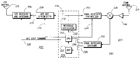
A combined receiver 200 that is incorporated into the handheld
communications transceiver 110 according to an exemplary embodiment of the
present invention is illustrated in FIG. 2. The handheld communications
transceiver
110 also contains transmitter circuits and other circuits that are not shown
and are not
relevant to the operation of this embodiment of the present invention. The
combined
receiver 200 of the exemplary embodiment is a multiple channel receiver that
has one
communications receiver channel and multiple GPS receiver channels. The
combined
receiver 200 has communications components 220 that are circuits used to
perform
the functions of a receiver channel used to receive communications signals,
such as
the signal transmitted by the base station 108. The combined receiver 200 also
has
GPS components 222 that contain receiver channels for receiving GPS signals
122 as
well as circuits to perform other functions of a GPS receiver that are used,
for
example, to determine the position of the GPS antenna 116. The combined
receiver
200 further has shared components 224 that are used to support the operation
of both
the communications and GPS receiver channels. The shared components 222 are
also
used for other functions that are not shown, including support of the
communications
transmitter functions of the handheld communications transceiver 110.
The communications components 220 of the exemplary embodiment include a
communications receiver synthesizer 204, an RF mixer 226, a communications
antenna 113, a communications RF amplifier 244 and a communications receiver
baseband processing unit 210. The communications components 220 of the
exemplary embodiment are used to receive signals transmitted along the
wireless
-10-
CA 02523123 2005-10-20
WO 2004/095718 PCT/US2004/012217
communications link 112. The received RF signal is captured by the
communications
antenna 113 of the exemplary embodiment and is routed to the RF amplifier 244
prior
to down-conversion by the RF mixer 226.
The Communications receiver synthesizer 204 generates an RF local oscillator
that is provided to the RF mixer 226 to properly down-convert the received RF
signal
to a baseband signal. In order to more clearly describe the functioning of the
combined receiver 200, the down-conversion processing is illustrated as a
single
mixer. Other circuitry, such as filtering and amplification stages, are not
shown but
are understood to be part of the internal processing of the RF mixer 226.
Further
embodiments of the present invention utilize multiple stage down-conversion
processes and/or provide a non-zero intermediate frequency as an output
instead of
the baseband output of the exemplary embodiment.
The communications receiver synthesizer 204 accepts a frequency reference
signal 236 that is generated by a reference oscillator 202 and derives a local
oscillator
(LO) output signal from the frequency reference signal 236 by multiplying the
frequency of the frequency reference signal 236 by a specified number. The
communications receiver synthesizer 204 accepts a frequency command 234 from
the
CPU 214 to allow the changing of the tuned frequency of the communications
channel. The communications frequency synthesizer 204 of the exemplary
embodiment is a "fractional-N" synthesizer that allows increased flexibility
in the
setting of the frequency of its output signal.
-11-
CA 02523123 2005-10-20
WO 2004/095718 PCT/US2004/012217
The frequency of the output signal of the communications receiver synthesizer
204 is based upon the frequency of the output of the reference oscillator 202.
Changes in the frequency of the output signal of the reference oscillator 202
are
directly reflected in the frequency of the communications receiver synthesizer
204
and therefore in the tuned RF frequency of the communications receiver., The
processing of the communication receiver baseband processing unit 210 produces
an
observed frequency error output 238. The observed frequency error output 238
indicates the measured difference between the received RF signal and the tuned
center
frequency of the receiver channel used to receive the communications signal.
The
exemplary embodiment of the present invention uses this measured error to
correct or
adjust the output frequency of the reference oscillator 202, as is described
below.
The GPS components 222 include a GPS reference synthesizer 206, a GPS
antenna 116 and a GPS receiver and baseband unit 208. The exemplary embodiment
contains multiple GPS components 222 that are either dedicated to a single GPS
satellite or timeshared to receive signals from multiple satellites using
conventional
techniques. The following description relates to one representative set of GPS
components 222 for the purposes of clarity and simplicity.
The GPS reference synthesizer 206 accepts a GPS synthesizer frequency
command 230 from the CPU 214. The GPS receiver and baseband unit 208 includes
multiple receiver channels that are used to receive and process GPS signals
122 from
multiple GPS satellites 120. The GPS receiver and baseband unit 208 accepts a
GPS
reference signal 209 from a GPS reference synthesizer 206 and uses this signal
to
-12-
CA 02523123 2005-10-20
WO 2004/095718 PCT/US2004/012217
derive one or more local oscillator signals for each GPS signal receiver
channel. The
output frequencies of the local oscillator output signals generated within the
GPS
receiver and baseband unit 208 are derived from the GPS reference synthesizer
output
209, which is derived from the output of the reference oscillator 202.
Therefore, any
changes in the frequency of the output signal generated by the reference
oscillator 202
are reflected by an equal and opposite proportional amount in the local
oscillator
signals generated within the GPS receiver and baseband unit 208 unless
measures are
taken to obviate this effect. The GPS receiver and baseband unit 208, which is
specific to each satellite, of the exemplary embodiment accepts an Automatic
Frequency Control (AFC) step command 228 to compensate for changes initiated
by
the CPU 214 in the output frequency of the reference oscillator 202, as is
described
below.
The shared components 224 include a central processing unit (CPU) 214, a
digital signal processing unit (DSP) 212 and a reference oscillator 202. The
CPU 214
and DSP 212 of the exemplary embodiment perform processing associated with the
present invention, as is described herein, as well as other functions in the
control and
operation of the combined receiver 200 and handheld transceiver 110 that are
not
relevant to the present invention. The reference oscillator 202 of the
exemplary
embodiment is essentially a crystal oscillator (X0) or possibly a temperature
controlled crystal oscillator (TCXO) that accepts a frequency adjustment
digital offset
command over an offset command interface 232. The digital offset command
adjusts
the output frequency of the frequency reference signal 236 to compensate, for
-13-
CA 02523123 2005-10-20
WO 2004/095718 PCT/US2004/012217
example, for observed output frequency errors of the reference oscillator 202.
This
error is determined by the DSP 212 from the highly accurate (in terms of
frequency)
communication signal 112 that is received by antenna 113. The reference
oscillator
202 generates a sinusoidal output that is maintained at a stable frequency
based upon
a crystal reference and the digital offset command. The exemplary embodiment
of the
present invention utilizes a reference oscillator 202 that has less frequency
accuracy,
due to manufacturing tolerances, cost considerations, and temperature
sensitivity, than
the frequency accuracy of the received communications signal. The exemplary
embodiment corrects or adjusts the frequency of the frequency reference signal
236
based upon tuning frequency errors observed for the received communications
signal
by changing the frequency offset command sent to the reference oscillator 202.
The exemplary embodiment of the present invention utilizes a transmitted
communications signal 112 that carries a digital data stream. The combined
receiver
200 uses conventional processing techniques on the received digital data
signal in
order to determine frequency tuning errors between the tuned frequency of the
receiver channel and the transmitted signal frequency of the received signal.
The
communications receiver baseband unit 210 of the exemplary embodiment converts
the phase modulated communications signal to baseband, so that phase errors
between
the local oscillator and the received signal are observed as phase offsets
within the
expected values of the baseband signal during the symbol sampling period of
the
receiver. The processing of the DSP 212 and CPU 214 operate as a frequency
reference adjustor to determine the frequency adjustment of the local
oscillator
-14-
CA 02523123 2005-10-20
WO 2004/095718 PCT/US2004/012217
frequency that will correct the observed phase errors in the local oscillator
output
produced by the communications receiver synthesizer 204 and properly track the
received signal, as is well known in the relevant arts. The CPU 214 then
provides this
frequency adjustment in the form of a digital frequency offset command 232 to
the
reference oscillator 202 to implement the required change in the local
oscillator
frequency.
The required adjustment to the frequency reference signal 236 output by the
reference oscillator 202 is a function of the relationship between the output
frequency
of the reference oscillator 202 and the output frequency of the communications
receiver synthesizer 204. An exemplary operation of the communications
components 220 has the communications frequency synthesizer 204 multiplying
the
frequency of the frequency reference signal 236 by forty-two (42). In this
example,
the digital frequency offset command provided to the reference oscillator 202
is the
frequency error observed for the received signal divided by forty-two.
Adjusting the
frequency to the reference oscillator 202 by tracking the received signal in
this
manner allows the accuracy of the reference oscillator 202 to be established
by the
frequency accuracy of the received signal. Adjustments in frequency can be
considered either as absolute values of frequency (i.e., the frequency
difference that is
to be implemented), or an adjustment can be considered in parts-per-million
(ppm).
Frequency errors and adjustments specified in ppm are sometimes more
convenient in
considering the operation of receivers that utilize synthesizers that have
signals with
-15-
CA 02523123 2005-10-20
WO 2004/095718 PCT/US2004/012217
different frequencies that are all derived from a common frequency reference
signal
236.
A reference oscillator 202 as is used by the combined receiver of the
exemplary embodiment of the present invention is illustrated in FIG. 3. The
reference
oscillator 202 has an oscillator circuit 302 that is controlled by a crystal
304. The
crystal is in parallel with a varactor tuning diode 308 that is driven by a 9-
bit digital to
analog converter (DAC) 310. The voltage output of the DAC changes the
capacitance
value of the varactor diode, thus adjusting the operating frequency of the
crystal
oscillator. The DAC output port represents a high impedance at the frequency
of the
crystal oscillator, so that it does not load down the oscillator circuit. This
allows the
output frequency of the reference oscillator 202 to be adjusted by providing
different
digital offset commands over the offset command interface 232.
The combined receiver 200 of the exemplary embodiment of the present
invention incorporates GPS components 222 that are able to simultaneously
receive
signals from multiple GPS satellites. The GPS receiver and baseband unit 208
accepts a GPS reference signal 209 that is generated by the GPS reference
synthesizer
206. In order to provide a stable reference signal for the receiving circuits
of the GPS
receiver and baseband unit 208, the GPS reference synthesizer 206 derives the
GPS
reference signal 209 from the frequency reference signal 236.
The GPS receiver and baseband unit 208 as used by the exemplary
embodiment of the present invention contains at least one receiver channels
that each
have an independent local oscillator. The GPS receiver and baseband unit 208
-16-
CA 02523123 2005-10-20
WO 2004/095718 PCT/US2004/012217
provides at least one numerically controlled oscillator (NCO) as a local
oscillator for
each receiver channel. The outputs of these NCOs are based upon the frequency
of
the GPS reference synthesizer 206. Changes in the output frequency of the GPS
reference synthesizer 206 directly affect the frequency of these NCOs and
therefore
the tuned frequency of all of the GPS receiver channels within the GPS
receiver and
baseband unit 208. The changes of the frequency of the output signal of the
reference
oscillator 202 that are made as part of the AFC processing of the exemplary
embodiment can cause disruption in the reception of the GPS signals by the GPS
receiver and baseband unit 208. The GPS signal and baseband unit 208 of the
exemplary embodiment obviates any disruption due to changes in the frequency
of the
frequency reference signal 236 by accepting an AFC step command 228 from the
CPU 214 that is synchronized with the frequency change command issued by the
CPU 214 to the reference oscillator 202. The AFC step command 228 is an
indication
of the frequency adjustment that is being applied to the reference oscillator
202. The
GPS reference synthesizer 206 generates a signal with a frequency that is a
known
multiple of the frequency reference signal 236. The CPU 214 provides a GPS
synthesizer command to the GPS reference synthesizer 206 that specifies the
number
by which the frequency of the frequency reference signal 236 is to be
multiplied. This
number similarly multiplies any change in the frequency of the frequency
reference
signal 236 and the AFC step command 228 provided to the GPS receiver and
baseband unit 208 also reflects this multiplier number. The AFC step command
228 is
applied to each NCO of the GPS receiver and baseband unit 208 at the time a
-17-
CA 02523123 2005-10-20
WO 2004/095718 PCT/US2004/012217
frequency change is made in the output of the reference oscillator 202 under
the
control of the CPU 214. The absolute frequency shift required for the output
of the
reference oscillator 202, GPS reference synthesizer 206, NCO outputs, as well
as the
originally determined adjustment requirement for the output of the
communications
receiver synthesizer 204, differ due to different absolute frequency values
for each of
these signals. The required frequency shifts for all of these signals,
however, equate
to the same part-per-million (ppm) value since they are all derived from a
common
frequency reference. This relationship of adjustments based upon ppm values
facilitates efficient processing in the CPU of the exemplary embodiment.
A portion of a GPS receiver channel 400 that is incorporated in the exemplary
embodiment of the present invention is illustrated in FIG. 4. The GPS receiver
channel 400 has an NCO 406 that accepts the GPS reference signal 209 and
generates
a local oscillator signal 418 that is used by the baseband circuits 414. The
baseband
circuits 414 accept a GPS signal 416 that has been converted to an appropriate
intermediate frequency and further conditioned by a preceding stage that is
not shown
for ease of understanding. The baseband circuits 414 process the GPS signal
416 in a
conventional manner and produce, among other data, an updated frequency
command
408 to the NCO 406 so that the received GPS signal 416 is properly tracked
according
to a closed loop tracking algorithm that is implemented by the GPS receiver
channel.
The NCO 406 accepts a GPS reference signal 209 upon which the output
frequency of the NCO is based. In order to accommodate changes in the
frequency of
the GPS reference signal 209 that are caused by adjustments to the reference
oscillator
-18-
CA 02523123 2005-10-20
WO 2004/095718 PCT/US2004/012217
202, the GPS receiver channel 400 of the exemplary embodiment of the present
invention receives an AFC step command that is added to the frequency command
408 in order to produce a modified frequency command 420. The AFC step
command 228 is used to adjust the relationship between the GPS reference
signal 209
and the local oscillator signal produced by the NCO 406 of the GPS receiver
channel
400 in response to the frequency adjustment that is applied to the reference
oscillator
202.
The AFC step command 228 has two components. One component is an AFC
step value 412 that contains the frequency shift amount that the GPS receiver
and
baseband unit 208 is required to accommodate. The CPU 214 of the exemplary
embodiment provides a properly formatted AFC step value 412 as is required by
the
design of the GPS receiver channel 400. The other component of the AFC step
command 228 is an AFC step clock 410 that is a synchronization signal that
corresponds to the time at which the frequency adjustment is applied to the
reference
oscillator 202 and therefore the time at which the output frequency of the
reference
oscillator 202 is changed or begins to change. These two components are
provided as
input to a step command latch 402. The step command latch 402 retains its
previous
value as a frequency adjustment output 422 until the AFC step clock 410 input
indicates the frequency adjustment is to be made. This is indicated by a
positive
going edge of the AFC step cloclc 410 in the exemplary embodiment. Upon this
indication, the frequency adjustment output 422 is changed to reflect the
received
AFC step value 412, and this value is added to the frequency command 408 by
adder
-19-
CA 02523123 2005-10-20
WO 2004/095718 PCT/US2004/012217
404. The sum of these two values is the modified frequency command 420 that is
used as a frequency command input to the NCO 406. This allows the frequency
shift
that is needed to accommodate changes in the frequency of the GPS reference
signal
209 to be directly made by the NCO 406 in anticipation of that change without
requiring the GPS signal re-acquisition processing that is conventionally
used, and
which may take on the order of several seconds for the case of weak GPS
signals.
The exemplary embodiment described above has a reference oscillator 202
that has a response time for frequency offset commands that is small relative
to the
received signal tracking loop time constant for the GPS receiver and baseband
unit
208. This allows the output of the GPS local oscillator, the NCO 406, to be
adjusted
in a step-wise manner, as is described above, while the frequency of the local
oscillator signal is maintained within the tracking bandwidth of the receiver
channel.
In such embodiments, the GPS receiver channels are considered to be non-
reference
receiver channels, i.e., receiver channels that are not used to receive a
signal to be
used for the adjustment of reference oscillator 202. Other embodiments of the
present
invention have non-reference receiver channels that have signal tracl~ing
bandwidths
that correspond to time constants that are short in relation to the response
time of the
reference oscillator 202 to offset frequency commands. This precludes step-
wise
adjustment of the local oscillators used by those non-reference channels since
the
output of the reference oscillator 202 will change more slowly than the local
oscillator
signal of the receiver channel. Improper tracking of the changing frequency of
the
frequency reference signal 236 by the local oscillator signal of the receiver
channel
-20-
CA 02523123 2005-10-20
WO 2004/095718 PCT/US2004/012217
may result in improper tracking of the received signal and the loss of signal
traclung
by the non-reference receiver channel.
An alternative embodiment of the present invention uses a shaping circuit to
properly shape the change in the NCO output frequency in response to the AFC
step
command 228. These embodiments recognize that the reference oscillator 202 has
a
certain time-domain response to frequency adjustment commands. This shaping
circuit implements a second time domain response that causes the frequency
command inputs that are provided to the NCO 406 to change in time with the
expected change in the frequency reference signal 236 and to therefore produce
a
more constant NCO output frequency as the frequency reference input to the NCO
changes. The second time domain response that is implemented by this shaping
circuit is selected to be close to the time domain response of the reference
oscillator
202 to frequency adjustment commands. An exact match of these two time domain
response provides optimal performance. It is to be noted, however, that a
matching of
these time domain responses that results in maintenance of the NCO output
within the
tracl~ing bandwidth of the receiver channel during adjustment of the reference
oscillator 202 is adequate to maintain tracking of a received signal.
A frequency response shaping circuit 500 according to this alternative
embodiment is illustrated in FIG. 5. The frequency response shaping circuit
500
accepts the same two components of the AFC step command 228 that are described
above. The AFC step command 412 is similarly latched into the step command
latch
402 in response to the AFC step clock signal 410.
-21-
CA 02523123 2005-10-20
WO 2004/095718 PCT/US2004/012217
In addition to the step command latch 402, the frequency response shaping
circuit 500 has a lookup ROM 504 that contains a stored time domain step
response
that matches the frequency change step response of the reference oscillator
202 and
synthesizer chain that is to be matched by the frequency shift of the output
of the
NCO 406 upon receipt of an AFC step command 228. In the example of the GPS
receiver given above, this is the step response of the reference oscillator
202 and the
GPS reference synthesizer 206 to an offset frequency command provided over the
offset frequency command interface 232. The contents of ROM 504 of this
embodiment are determined by characterization of this step response performed
before or during the circuit manufacturing process.
The content of the loolcup ROM 504 is addressed by a counter output 512.
The counter output 512 of this embodiment is a multiple data line signal that
contains
multiple data bits corresponding to the count value of counter 502. The
counter 502
has a clock input 508. The counter starts with a counter output 512 value of
zero and
increments the value of the counter output with each cycle of the clock input
508.
The period of the clock input 508 is chosen according to the time scale of the
time
domain step response data stored within lookup ROM 504. Counter 502 produces a
maximum count output 506, which indicates that the counter has reached its
maximum count value. The maximum count output 506 is provided to a hold input
of
the counter 502 that causes the counter output 512 to stop increasing so that
the
counter output 512 retains its value.
_22_
CA 02523123 2005-10-20
WO 2004/095718 PCT/US2004/012217
The counter 502 of this embodiment has a reset input which causes the counter
output 512 to be reset to zero. This also causes the maximum count output 506
to be
de-asserted. This allows the counter output 512 to begin counting from zero
and then
be incremented with each cycle of the clock input 508. The period of the
cloclc input
508 of this embodiment is selected to implement the required time domain
shaping of
the frequency step in the output of the NCO 406. The output of the counter 502
is
provided as an addressing input to the lookup ROM 504. The data of the lookup
ROM 504 that corresponds to the address of the current count value contained
on the
counter output 512 is produced as a first input to multiplier 514. The step
cornlnand
latch 402 latches the AFC step command 412 as described above and provides
this
output as a second input to multiplier 514. This results in the magnitude of
the AFC
step command 412 being shaped according to the time domain response values
stored
within lookup ROM 504. The output of multiplier 514 is provided to adder 404
and is
summed with the frequency command 408, as is described above.
The counter output 512 increases with each cycle of the clock input 508 until
the maximum count is reached. The maximum count is indicated by the maximum
count output 506, which is supplied to the hold input of the counter 502. This
causes
the counter output 512 to stop increasing and the output of multiplier 514 to
be held
constant.
Further embodiments of the present invention have different frequency
generation circuit configurations for the various LO frequencies used by the
multiple
. receiver channels. One embodiment utilizes an alternative frequency
synthesizer
-23-
CA 02523123 2005-10-20
WO 2004/095718 PCT/US2004/012217
chain 600 that is illustrated in FIG. 6. The alternative frequency synthesizer
chain
600 has a reference oscillator 202a and communications receiver synthesizer
204 that
are similar to the combined receiver 200. The reference oscillator 202a
produces a
reference signal 236 that is an input to the communications receiver
synthesizer 204.
This alternative embodiment of the present invention does not adjust the
output
frequency of reference oscillator 202a but rather compensates for frequency
offsets of
the reference oscillator 202a by commanding different frequency multiplication
values within the communications receiver synthesizer 204. The output of the
communications receiver synthesizer 204 therefore has a frequency accuracy
that is
determined by the frequency accuracy of the received communications signal
even
though the reference oscillator 202 is not directly adjusted. The GPS
reference
synthesizer 206a therefore has a stable input frequency reference and is able
to
produce a signal with a stable output frequency. These embodiments adjust the
multiplication factor used by the GPS reference synthesizer 206a whenever the
multiplication factor of the communications receiver synthesizer 204 is
adjusted in
response to an observed frequency error in the communications signal receiver.
The
GPS reference synthesizer output 209 is then used as described above.
A processing flow diagram 700 according to an exemplary embodiment of the
present invention is illustrated in FIG. 7. The processing flow begins by
determining,
at step 702, a frequency adjustment that is to be provided to the reference
oscillator
202. This determination is able to be performed immediately or after a delay
according to the requirements of the particular embodiment. The processing
then
-24-
CA 02523123 2005-10-20
WO 2004/095718 PCT/US2004/012217
provides, at step 704, data to the local oscillator of a second receiver. The
data
provided in this step indicates the magnitude of the frequency adjustment that
will be
applied to the reference oscillator 202. The processing then commands, at step
706,
the reference oscillator to implement the frequency adjustment. The processing
then
(preferably simultaneously) provides, at step 708, to the local oscillator of
the second
receiver an indication of the frequency adjustment. The CPU 214 provides this
data
in the exemplary embodiment described above. The indication of the frequency
adjustment in the exemplary embodiment is in the form of an AFC step cloclc
signal
410, as is described above. The processing of the exemplary embodiment then
reconfigures, at step 710, the local oscillator of the second receiver so as
to maintain a
constant frequency output during the change in reference frequency signal that
results
from the frequency adjustment. The reconfiguration is able to be a step-wise
process
or a process with a time domain response, as is described above.
Accordingly, preferred embodiments of the present invention allow more
effective sharing of a single frequency reference oscillator between multiple
receiver
channels in a multiple channel receiver. These embodiments allow for AFC
processing to be performed on the single frequency reference oscillator by
using one
receiver channel while minimizing the affect of the AFC processing on the
other
receiver channels that derive a local oscillator from that frequency reference
oscillator. This results in cost, size and power savings by obviating the need
for a
separate frequency reference for the multiple receiver channels, such as for
the
multiple receiver channels of a multiple channel receiver that simultaneously
receives
-25-
CA 02523123 2005-10-20
WO 2004/095718 PCT/US2004/012217
both communications and GPS signals, while at the same time preventing loss of
tracking of the received signal. In the preferred embodiment, GPS signal
tracl~ing is
not lost because tuned frequency changes in the GPS receiver are limited to
less than
the tracking bandwidth of the GPS receiver when the AFC processing adjusts the
output frequency of the frequency reference oscillator.
The present invention can be realized in hardware, software, or a combination
of hardware and software. A system according to a preferred embodiment of the
present invention can be realized in a centralized fashion in one information
processing system, or in a distributed fashion where different elements are
spread
across several interconnected information processing systems. Any land of
information processing system - or other apparatus adapted for carrying out
the
methods described herein - is suitable. A typical combination of hardware and
software could be a general purpose computer system with a computer program
that,
when being loaded and executed, controls the computer system such that it
carries out
the methods described herein.
The present invention can also be embedded in a computer program product,
which comprises all the features enabling the implementation of the methods
described herein, and which - when loaded in a information processing system -
is
able to carry out these methods. Computer program means or computer program in
the present context mean any expression, in any language, code or notation, of
a set of
instructions intended to cause a system having an information processing
capability to
perform a particular function either directly or after either or both of the
following a)
-26-
CA 02523123 2005-10-20
WO 2004/095718 PCT/US2004/012217
conversion to another language, code or, notation; and b) reproduction in a
different
material form.
Each information processing system may include, inter alia, one or more
information processing devices and/or computers and at least a machine
readable
medium allowing a device to read data, instructions, messages or message
packets,
and other machine readable information from the machine readable medium. The
machine readable medium may include non-volatile memory, such as ROM, Flash
memory, Disk drive memory, CD-ROM, and other permanent storage. Additionally,
a computer medium may include, for example, volatile storage such as RAM,
buffers,
cache memory, and network circuits. Furthermore, the machine readable medium
may comprise information in a transitory state medium such as a network link
and/or
a networlc interface, including a wired network or a wireless network, that
allow a
computer to read such machine readable information.
Although specific embodiments of the invention have been disclosed, those
having ordinary skill in the art will understand that changes can be made to
the
specific embodiments without departing from the spirit and scope of the
invention.
The scope of the invention is not to be restricted, therefore, to the specific
embodiments, and it is intended that the appended claims cover any and all
such
applications, modifications, and embodiments within the scope of the present
invention.
What is claimed is:
-27-