Note: Descriptions are shown in the official language in which they were submitted.
CA 02523163 2005-12-14
0
-1-
ACETABULAR RIM CUTTER
This invention relates to an acetabular rim cutter which can be used for
cutting the outer rim of an acetabulum to form an annular seating surface to
receive
a flanged acetabular cup or a rim cutter and acetabulum reamer which has the
dual
function of reaming an acetabulum and then cutting its rim.
Rotary cutters are known but if a surgeon were to attempt to use such a rotary
cutter for treating the rim of an acetabulum he would have difficulty in
locating it with
sufficient accuracy.
There are also difficulties in cutting the rim of an acetabulum so that the
annular seating surface is a predetermined distance from the base of the
acetabulum and that the part spherical bearing surface of the cup is at a
desired
depth from the cut seating surface so that there is a regular seating surface.
The
present invention is intended to overcome some of the difficulties referred to
above.
According to the present invention an acetabular rim cutter comprises an
annular cutting face provided on a rotatable carrier, means for attaching the
carrier
to a rotation means and a guide element axially aligned with said cutting face
to
locate and align the cutting face on the acetabulum with which it is to be
used.
Preferably the guide element is axially movable in relation to the cutting
face,
and resilient means are provided for biasing it axially away therefrom.
Thus, the guide element can be of a part-spherical shape which locates in the
acetabulum and ensures that the axis of the annular cutting face is correctly
aligned.
In a preferred embodiment the guide element is freely rotatable in relation to
the rotatable carrier and it can be made from, for example, a synthetic
plastics
material.
CA 02523163 2011-12-19
74705-39
-2-
The annular cutting face is preferably provided with radial cutting teeth.
An operating handle can be provided which is axially aligned in relation
to the rotatable carrier and which is free to rotate in relation thereto thus
providing
means for the surgeon to operate the equipment.
The rotatable carrier can be connected to an extension the end of which
is adapted to receive the rotation means and on which the operating handle is
located.
Depth cutting control means are also preferably provided which act to
determine the depth and cut in relation to the base of the acetabulum with
which it is
to be used.
In order to provide a modular construction a number of guide elements
can be provided which are used respectively to provide different depths of cut
and
which can be of different diameters to appropriately suit the acetabular which
is to be
cut.
The apparatus can also include an acetabulum surface reamer which is
adapted for attachment to the rotation means in place of the rotatable carrier
and the
guide element.
According to a further aspect of the present invention, there is provided
an acetabular cutter for preparing an acetabulum comprising: a hollow handle;
a drive
shaft extending along an axis rotatably and slidably mounted within said
hollow
handle, said shaft having a rotating head at a first end and a second end
connected
to a power source; an acetabular rim cutter connected to said drive shaft
rotating
head for axial and rotational movement thereof at the first end thereof, said
cutter
having teeth thereon concentric about a rotational axis of said head and the
teeth,
upon rotation, forms a planar annular cutting face extending in a plane
perpendicular
to the drive shaft axis capable of forming an outwardly facing annular planar
surface
CA 02523163 2011-12-19
74705-39
-2a-
around the circumference of the acetabulum in a plane perpendicular to the
drive
shaft axis; a guide element mounted on said handle freely rotatable with
respect to
the drive shaft for engaging the acetabulum and extending beyond said first
drive
shaft end, the guide element being axially movable along said rotational axis,
the
acetabular rim cutter movable with respect to the guide element in the
direction of the
axis of the drive shaft and having a diameter greater than a maximum diameter
of the
guide element; and a spring element acting between the guide element and the
acetabular rim cutter along in the direction of the axis between the handle
and the
guide element and a stop means for limiting the travel of the rim cutter along
the axis
with respect to the guide element.
According to another aspect of the present invention, there is provided
a kit for preparing an acetabulum comprising: a rotary drive tool having a
hollow
handle with a rotatable axially extending drive shaft therein, the drive shaft
having a
drive head at a first end and a connection for a power source at a second end;
a
plurality of dome shaped cutting elements for preparing the acetabulum
mountable on
said drive head; a plurality of rim cutting elements mountable on said drive
head for
rotational and axial movement therewith and having cutting teeth located along
a
circumference concentric about a rotational axis of said drive head, said
teeth, upon
rotation, forms an annular planar cutting face extending in a plane
perpendicular to
the rotational axis of the drive head capable of forming an outwardly facing
annular
planar surface around the circumference of the acetabulum in a plane
perpendicular
to the drive shaft axis; and a plurality of guide elements for mounting on the
handle
freely rotatable with respect to the drive shaft and a spring element for
acting
between the rim cutter and the guide element, the acetabular rim cutter
movable with
respect to the guide element in the direction of the axis of the drive shaft
and having
a diameter greater than a diameter of the guide element, each guide element
including a stop means for limiting the movement of a rim cutter with respect
to the
guide element in the axial direction of the drive shaft.
CA 02523163 2011-12-19
74705-39
- 2b -
The invention can be performed in various ways but one embodiment
will now be described by way of example and with reference to the accompanying
drawings in which:
Figure 1 is a side elevation of an acetabular rim cutter according to the
present invention;
Figure 2 is a cross-sectional view on the lines II-II of Figure 1;
Figure 3 is a cross-sectional end view on the line III-III of Figure 2;
CA 02523163 2005-12-14
-3-
Figure 4 is a side view of the rim cutter with the rotatable
carrier removed;
Figure 5 is an isometric view of the rim cutter with the rotatable
carrier removed;
Figure 6 is an enlarged side view of part of one end of the rim cutter
with the rotatable carrier removed;
Figure 7 is an end view of the rotatable carrier showing the annular
cutting face;
Figure 8 is an enlarged diagrammatic side elevation of locking apparatus
for determining the depth of cut;
Figure 9 is a view similar to Figure 7 with the parts in a second position;
Figure 10 is a diagrammatic view showing the apparatus ready for use;
Figure 11 shows a prosthetic acetabular cup in place in a reamed
acetabulum;
Figure 12 is a side view of an acetabulum reamer which can be
attached to the rotation means in place of the rotatable carrier; and,
Figure 13 is a plan view of the acetabulum reamer shown in
Figure 11.
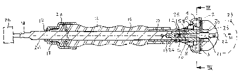
As shown in the drawings an acetabular rim cutter according to the present
invention comprises an annular cutting face 2 which has radial cutting teeth 3
and
which is provided on a rotatable carrier 4, the construction of which is most
clearly
CA 02523163 2005-12-14
-4-
shown in Figure 6. The carrier 4 is attached to a hollow drive spindle 5 which
has a
triangular shaped end piece 6, most clearly shown in Figures 4, 5 and 6. The
carrier
4 has a hexagonal shaped opening 7 with corners 8 and which is dimensioned so
that the distance of the wall between a first corner 8 and the next but one
corner 8
circumferentially spaced around the hexagon is slightly greater than the
length of the
sides of the triangular end piece 6 between its corners 10 which are
chamferred to
accommodate the corners 8 of the hexagon. Each corner 10 has a re-entry slot
10a
one wall of which is provided by a corner 10 and the other of which is a
projecting lug
11. The width of the slot 10a is adapted to receive and locate the wall of the
carrier
between two of the corners 8. Thus the carrier 4 can be passed over the
triangular
end piece 6 and then angularly rotated so that each of the corners 10 of the
triangular end piece are aligned with one of the sides of the hexagon 7
between two
of the corners 8. Movement in axial directions is prevented by the walls of
the slot
10a.
Extending over the spindle 5 is a locking sleeve 12 which is biased towards
the carrier by a spring 13 and the end of which is of similar shape to the
triangular
shaped end piece 6 but its corners 12a have flats 12b which are dimensioned to
engage three of the sides of the hexagon 7 of the carrier 4. The corners 12
also have
slats 14 which can engage the abutment 11. In Figure 6 the sleeve is in its
withdrawn position adjacent the spring bias and ready to receive the carrier
4. With
the carrier in position the spring 13 will push the sleeve in the direction of
the arrow A
so that the flats 12b will engage the carrier so that it will rotate with the
sleeve 12.
Located on the hollow drive spindle 5 is an extension shaft 15 on which is a
freely rotatable operating handle 16 which has a pair of arcuate prongs 17,
the inner
diameters of which are less than the diameter of the extension shaft 15, and
which
engage a portion 26 of the shaft 15 which is of reduced diameter. The end of
the
handle and the prongs 17 are held in position by the resilient effect. The
prongs 17
are also held by a retainer 27
CA 02523163 2005-12-14
=
-5-
The outer end of the extension shaft 15 carries a boss 18 for connecting it to
a rotary power drive of known type and which is indicated by reference letters
PD in
Figure 2.
Also mounted on the extension shaft 15 is a sleeve 19 which extends into the
locking sleeve 12 and retains the spring 13.
The hollow drive spindle 5 has a bore 20 in which is mounted a location shaft
21 the outer end 22 of which is screw threaded for attachment to a guide
element
23 which has a part-spherical shape. The inner end 24 of the bore 20 has a
location
groove 25 which can be engaged by a resiliently biased plunger 28 which is
carried in
the triangular end piece 6 (as shown in Figure 3).
The shaft 21 is biased to the right, as shown in Figure 2, by means of a
compression spring 30 mounted between the part spherical guide element 23 and
the hollow drive spindle 5. In Figure 2 the compression spring 30 is shown in
a
compressed position with the inner end 24 of the shaft 21 pushed into the full
length
of the bore 20. With the compression spring 30 in its expanded position the
guide
element 23 is pushed out to the position shown in chain lines on Figure 2 in
the
direction of the arrow 31.
Figures 8 and 9 show how the spring loaded plunger 28 operates. The
plunger has an engagement ball 32 which is pressed against the location shaft
21.
The shaft 21 is first pushed into the bore 20 until the groove 25 is engaged
by the
plunger ball 32 which acts to hold it in position. The guide element is thus
held in the
position shown in chain lines in Figure 2. When pressure is applied via the
handle 16
and with the guide element in the acetabulum the shaft 21 moves up the bore
and
the ball 32 merely presses against the side of the shaft. The movement of the
bore
is against the pressure of the spring 30.
CA 02523163 2005-12-14
-6-
In an alternative construction (not shown) the spring loaded plunger 28 can
be replaced by a resilient 0-ring which can engage the groove 25 and can be
mounted on the bore 20.
A location guide 35 of known kind is provided on the handle 16.
Figures 10 and 11 show how the acetabular rim cutter, according to the
present invention, can be used. The intention is to trim the outer edges 39 of
an
acetabulum 40 by machining an annular seating surface 41 as shown in Figure
11.
A flanged acetabular cup having an outwardly projecting flange 43 can now be
seated on the annular seating surface 41. In the arrangement shown the cup is
a
close fit in the acetabulum but it will be appreciated that if, for example,
the cup was
to be held by cement then there could be an appropriate gap and spacers
between
the cup and the bone, as shown by chain lines 45.
Figure 10 shows the operative end of the acetabular rim cutter according to
the present invention and the same reference numerals are used to indicate
similar
parts to those shown in the other Figures. The guide element 23 carried on the
shaft
21 is in its extended position as caused by the spring 30 being expanded and
it will
be seen that the guide element 23 is axially aligned with the annular cutting
face 2
by the rotatable carrier 4, although the guide element 23 is free to rotate in
relation
to the carrier 4. With power applied through the shaft 15 the carrier is
rotated and is
guided by the guide element 23 to the appropriate position to cut the annular
bearing
surface 41. The precise angles of cut can be determined in known manner using
the
guide 35.
The depth of cut of the annular bearing surface 41 is determined by the
length of the shaft 21 which can be arranged so that the depth of the cut in
relation
to the base of the acetabulum 44 can be previously determined according to the
length of the shaft 21. Thus, the surgeon can be provided with a series of
cups of
CA 02523163 2005-12-14
-7-
different shapes and shaft lengths to provide a modular construction which can
be
used in different circumstances depending upon the requirements of the type of
acetabular cup used and the surgical implications.
The length of the shaft 21 therefore acts as depth cutting control means.
The guide element 23 can be made of any suitable material, for example
metallic material.
Figures 12 and 13 show an acetabulum reamer which can be used with the
acetabulum rim cutter. The reamer 50 has a dome shaped portion 51, the outer
surface of which is substantialy part-hemispherical, and which is provided
with a
number of openings 52 which can be of any suitable shape but are shown as
circular.
These openings are provided with sharp corners 53 so that they will have a
reaming
effect when the reamer is placed in an acetabulum and rotated. This type of
reamer
is sometimes referred to as being of a "cheese-grater type".
The reamer has a base 54, the plan shape of which is best shown in Figure
13. It will be seen that the shape is similar to the shape of the carrier 4
although it
does not have the teeth 3. The same reference numerals are used to indicate
similar
parts to the carrier 4, thus, it has a hexagonal shaped opening 7 with corners
8, the
dimensions are the same as those of the carrier.
The reamer can therefore be used with the rim cutter by removing the
rotatable carrier 4 and replacing it with the reamer 50 thus enabling the
apparatus to
have a dual purpose.
The reamer can be attached first and used to ream the acetabulum with
which it is to be used, the reamer can then be removed and replaced by the rim
cutter.
CA 02523163 2005-12-14
=
-8-
The acetabular rim cutter or rim cutter and acetabulum reamer combined may
particularly, although not exclusively, adapted for use with apparatus as set
for in
EP 0 650 706 and EP 0 650 707 for implanting an acetabular cup utilizing a
loading
tube.