Note: Descriptions are shown in the official language in which they were submitted.
CA 02523766 2005-10-24
WO 2004/100198 PCT/NL2004/000267
Electromagnetic actuator
Field of the invention
The present invention relates to an electromagnetic actuator for operating at
least one
movable contact of a switch into a switched-on position or a switched-off
position, wherein
the electromagnetic actuator has a first magnetic circuit with a switching-on
coil for
making a movable and a fixed pole body move towards one another until the
switched-on
position is reached, a second magnetic circuit, separate from the first
magnetic circuit, with
a permanent magnet and a retaining plate joined to the movable pole body, for
holding the
actuator in the switched-on position against any spring or other forces when
the switching-
on coil is not energised, and a switching-off coil that operates to counteract
the magnetic
field in the second magnetic circuit so that the actuator can return to a
switched-off
position. The second magnetic circuit contains the permanent magnet, the
retaining plate,
the switching-off coil and a circuit body closing the second magnetic circuit,
wherein the
second magnetic circuit.provides an increasing force of attraction between the
circuit body
and the retaining plate during the movement from the switched-off position
into the
switched-on position.
In further aspects this invention relates to a method for the production of an
electromagnetic actuator and to an assembly for fixing an actuator, such as an
actuator
according to the present invention, in a switching installation which has at
least one
movable contact of a switch.
State of the art
An electromagnetic actuator of this type is disclosed in International Patent
Publication WO 99/14769. As a result of the separate magnetic circuits, the
actuator can be
optimised as far as the switching-on and switching-off speeds and the
requisite switching-
on and switching-off energy are concerned. However, the actuator described in
this
publication can be even further improved, both in terms of operational use of
the actuator
and in terms of production of the actuator.
Summary of the invention
The aim of the present invention is to provide an electromagnetic actuator
that is
easier to produce, at lower cost, and that is more efficient in use compared
with the state of
CA 02523766 2005-10-24
WO 2004/100198 PCT/NL2004/000267
2
the art. .
According to the present invention an electromagnetic actuator in accordance
with
the type defined in the preamble is provided, wherein, in the axial direction
of the actuator,
the switching-off coil is positioned closer to the retaining plate than the
permanent magnet.
As a result of this modified positioning of permanent magnet and switching-off
coil
compared with the actuator known from patent publication WO 99/14769, the
operation of
the switching-off coil is more effective, as a result of which less energy is
needed for the
switching-off action of the present actuator.
A further example of an electromagnetic actuator is disclosed in US patent
application US-A-5 864 274. This type of actuator includes a cylindrical soft-
iron vessel
with permanent magnets arranged to form a shunt-magnetic gap with the inside
wall of the
soft-iron vessel. The neck of the flux conducting disk is surrounded by a
current winding.
A magnetically attractable pole disk lies on the neck of the soft-iron vessel.
An electrically
conducting ring is fastened to the pole disk. The pole disk activates
mechanical and/or
electrical safety devices. The system is activated by a current impulse sent
to the current
winding. This actuator does not comprise a switching-on coil, and in the case
of no external
activation of the coil, the actuator returns to its normal position, in which
the pole rests
against the (neck of the) flux conducting disk. As described, this actuator is
arranged to
relatively quickly push away the pole disk for a short time, which is achieved
by forcing the
magnetic flux to move away from the pole dislc, and by using the short-circuit
conducting
ring to provide a push away force. This is made possible by having the
magnetic circuit
formed by the soft-iron vessel, the permanent magnet, flux conducting disk and
pole disk,
in which the diameter of the permanent magnet is smaller than the diameter of
the soft-iron
vessel (the permanent magnet lies within the soft -iron vessel).
However, in the present invention, the switching-off action is initiated by
counteracting the magnetic flux of the permanent magnet, which is holding the
retaining
plate, by a magnetic flux generated by the switching-off coil but in the same
magnetic flux
path. This allows to put the permanent magnet at a more radially outward
located position
than the position taught by US-A-5 864 274, thus ensuring that the moveable
pole body
(part of the primary circuit of the switching-on coil) is not influencing the
secondary
magnetic circuit of the actuator. This allows to make a more compact actuator,
requiring
less length, as the elements of the holding arrangement (permanent magnet,
fitting body,
etc) can be positioned substantially co-axially with parts of the switching-on
arrangement
CA 02523766 2005-10-24
WO 2004/100198 PCT/NL2004/000267
3
(in particular the relatively large moveable pole body).
In a further embodiment the permanent magnet is a disc-shaped magnet, the pole
orientation of which is parallel to the axis of the disc-shaped magnet.
Permanent magnets
of this type are easy and inexpensive to produce, especially in comparison
with the
permanent magnet described in WO 99/14769 that requires a pole orientation in
the radial
direction. Furthermore, the production tolerances can be greater with the
present disc-
shaped permanent magnet because the second magnetic circuit runs differently
and an axial
tolerance is easier to eliminate than a radial.
In a fizrther embodiment the actuator comprises essentially cylindrical
elements. The
cylindrical elements from which the actuator is made up are in general easy to
produce with
the use of techniques known per se, for example with the use of a lathe. The
cylindrical
structure of the actuator is also more efficient compared with the state of
the art in respect
of the magnetic circuit produced and the amount of space that the actuator
talces up.
Furthermore, the various elements can be assembled easily, for example by
means of
(screw) fasteners and/or press fittings.
In yet a further embodiment the actuator comprises cylindrical elements in the
first
and second magnetic circuit that are made of steel, for example flee-cutting
steel. This
material is less expensive and easier to machine than the generally customary
magnetic tin
plate. It is true that this results in a loss of magnetic effectiveness, but
this can easily be
compensated for and is not outweighed by the economic advantage achieved.
In a fizrther embodiment the electromagnetic actuator comprises a movable
shaft
j oined to the movable pole body, which shaft can move relative to the fixed
pole body by
means of a plain bearing. The use of a plain bearing offers the advantage that
the actuator is
closed off from the environment, so that no magnetisable material and/or other
contamination can accumulate on the pole bodies.
Furthermore, in a further embodiment of the present electromagnetic actuator
the
movable pole body can move only in the axial direction relative to the circuit
body by
means of a plain bearing. This simple and inexpensive fixing is made possible
by the
cylindrical construction of the actuator.
So as also to prevent magnetisable particles or other contaminants from the
outside
accumulating in the air gap in the second magnetic circuit, the actuator is
provided with a
dust cap that screens off the air gap between a circuit body (where the
circuit body closes
the second magnetic circuit between permanent magnet and retaining plate) and
the
CA 02523766 2005-10-24
WO 2004/100198 PCT/NL2004/000267
4
retaining plate. Once again, such a dust cap, which, of course, must provide
room for the
possible movement of the various components in the actuator, is easy and
inexpensive to fit
because of the cylindrical construction.
In a further aspect the present invention relates to a method for assembling
an
actuator according to the present invention, wherein at least two of the
cylindrical elements
are fixed to one another by means of a screw fastener. As a result of the
cylindrical
structure, this is easily possible by making suitable holes in the cylindrical
elements.
As an alternative, or for specific parts of the actuator, in a further
embodiment at least
two of the cylindrical elements can be fixed to one another by a press fit.
This is
advantageous in particular if two elements, for example, have to be aligned in
the axial
direction during production. For example, in the actuator according to US-A-5
X64 274, the
flux conducting disk and edge of the soft-iron vessel need to be aligned, e.g.
by machining
the disk and/or the edge of the soft-iron vessel. This machining is an
additional step, which
will raise the cost of the actuator. Furthermore, iron parts may be attracted
by the
permanent magnet, which iron parts will be difficult to remove again. In the
actuator
manufactured according to this embodiment of the present invention, an adapter
body,
which together with the housing and a fixing body, by means of which the
permanent
magnet is fixed to the housing, forms the circuit body closing the second
magnetic circuit,
can be aligned with the fixing body, so that in the switched-on position these
two parts
precisely butt up against the retaining plate. In this way the customary
grinding operation
for the contact surfaces becomes superfluous.
In known actuators, e.g. as described in US-A-5 g64 274, the permanent magnet
must
be located inside a vessel shaped body, but can not touch the inside wall of
the vessel. This
is a very cumbersome manufacturing step, both with respect to proper
positioning, but also
because there is a chance the magnet will be pulled to the bottom of the
vessel with great
force, resulting in possible brealung of the permanent magnet. In the present
invention, the
permanent magnet may be put in the right position by shifting, after which the
alignment
may take place.
In yet a further aspect the present invention relates to an assembly for
fixing an
actuator, such as an actuator according to the present invention, in a
switching installation
which has at least one movable contact of a switch, wherein the axial axis of
the actuator is
essentially perpendicular to the direction of movement of the operating means
for the at
least one movable contact of the switch. As a result of such an arrangement, a
switching
CA 02523766 2005-10-24
WO 2004/100198 PCT/NL2004/000267
installation can be produced that makes efficient use of the available space.
It is pointed out
that in the state of the art (see, for example, the abovementioned patent
publication WO
99/14769 or the US Patent Publication US-A 2002/0093400 the direction of
movement of
the actuator is parallel to the direction of movement of the contacts of the
switch(es). Of
course, the actuator according to the invention can also be used in this way.
In a further embodiment the assembly furthermore comprises transmission means
with a predetermined transmission ratio between the movement of the actuator
and the
movement of the operating means for the at least one movable contact of the
switch. If, for
example, one actuator in the assembly drives three movable contacts of a
switch, the
predetermined transmission ratio is between 1:2 and 1:2.5 and when used with
the
conventional vacuum switches is preferably 1:2.2. The transmission ratio makes
it possible
to achieve an efficient design of the actuator (and/or switching
installation), with which
design specifications, such as switching-on and switching-off time, energy
required for the
° switching-on and switching-off coil, design of further energy storage
means (contact
pressure springs, compensation springs, etc.) are optimised.
Brief description of the drawings
The present invention will now be discussed in more detail on the basis of a
number
of illustrative embodiments with reference to the appended drawings, in which
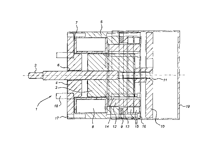
Fig. 1 shows a cross-sectional view of one embodiment of the electromagnetic
actuator;
Fig. 2 shows a perspective view of a set-up of electromagnetic actuator with
drive
elements and fixing.
Detailed description of illustrative embodiments
A cross-sectional view of one embodiment of an electromagnetic actuator 1 is
shown
in Fig. 1. The actuator 1 has a movable shaft 2 that can be connected
(directly or indirectly)
to a moving contact of a switch (not shown). Actuators for operating switches
in medium
voltage installations, for which the present actuator 1 is also suitable, are,
for example,
disclosed in the patent publication WO 99/14769, which must be considered to
have been
incorporated here by means of reference.
The actuator 1 comprises a first (movable) pole body 3 joined to the movable
shaft 2
and a second (fixed) pole body 4, which is joined to a housing 5. The movable
shaft 2 can
CA 02523766 2005-10-24
WO 2004/100198 PCT/NL2004/000267
6
move relative to the second pole body 4 by means of a plain bearing 6. A first
coil holder 7,
with a switching-on coil 8 therein, is positioned at the location of the air
gap between the
first pole body 3 and second pole body 4. By malting current flow through the
switching-on
coil 8, a magnetic field is generated that runs via the housing 5, first pole
body 3, second
pole body 4 and the air gap between the first and second pole body 3, 4 (the
first and
second pole body 3, 4 and the housing 5 being made of magnetically conducting
material).
As a result a force of attraction is produced between the first and second
pole body 3, 4, as
a result of which the movable shaft 2 moves to the left (and thus switches on
the switch
connected to the actuator).
To hold the actuator 1 in this switched-on position without energy being
needed to
energise the switching-on coil 8, a second, separate magnetic circuit is
provided (see also
the abovementioned patent publication WO 99/14769). In the embodiment shown
the
second magnetic circuit contains a permanent magnet 9 in the form of a disc-
shaped ring,
the north/south orientation of which is parallel to the axis of the disc-
shaped ring. This
makes production of the permanent magnet 9 simpler and less expensive and also
malees
the insensitivity to tolerance greater compared with the state of the art. In
the embodiment
shown, the movable shaft 2 is joined to a retaining plate 10 (for example as
shown with a
screw fastener 11). The permanent magnet 9 is joined to the housing 5 with the
aid of a
fixing body 13 (and, for example, with screw fasteners 16). An adapter body 12
in the form
of a cylinder provides for closure of the magnetic circuit from the one pole
of the
permanent magnet 9, via housing 5, adapter body 12, retaining plate,10 and
fixing body 13
to the other pole of the permanent magnet 9. The second magnetic circuit
therefore
comprises the permanent magnet 9, retaining plate 10 and a circuit body, which
contains
part of the housing 5, the fixing body 13 and the adapter body 12, closing the
second
magnetic circuit. In order to obtain this magnetic circuit there is an air gap
between
permanent magnet 9 and adapter body 12 and between fixing body 13 and adapter
body 12.
The first pole body 3 can move relative to the adapter body 12 only in the
axial direction by
use of a plain bearing 14.
As soon as the actuator 1 is energised with the aid of the switching-on coil
8, the
retaining plate 10 will move to the left in the drawing, as a result of which
air gaps between
retaining plate 10 and the fixing body 13 and between retaining plate 10 and
adapter body
12 will become increasingly smaller. The force of attraction of the second
magnetic circuit
becomes very high when the said air gap is sufficiently small, which makes a
substantial
CA 02523766 2005-10-24
WO 2004/100198 PCT/NL2004/000267
7
contribution to forcing the actuator 1 into the switched-on position. In the
switched-on
position (in which the air gaps have virtually completely disappeared) the
force of
attraction on the retaining plate is sufficient to hold the actuator 1 in this
position against
any forces acting in the opposite direction.
As discussed and explained in the patent publication WO 99/14769, the magnetic
circuits of the switching-on coil 8 and the permanent magnet 9 are completely
separate.
To switch off the actuator, a switching-off coil 15 is provided, which is also
fitted in
a coil holder. The switching-off coil 15 is sized such that in the case of
correct actuation
this counteracts the magnetic field of the permanent magnet 9, so that the
energy that has
been stored in a contact pressure spring of the switch to be operated and an
optional
additional switching-off spring (not shown) is sufficient to move the movable
shaft 2 fully
back.
Compared with the actuator shown in the publication WO 99114769, the positions
of
the switching-off coil 15 and permanent magnet 9 have been reversed. As a
result of the
position of the switching-off coil 15 in the present actuator 1, the latter
can operate more
effectively, as a result of which it can be made smaller and in operation
requires a lower
power feed in order to obtain the same switching-off action.
The second magnetic circuit in the present actuator 1 is longer compared with
the
actuator shown in patent publication WO 99/14769, as a result of which the
magnetic
resistance is higher. However, this can easily be compensated for by using a
stronger
permanent magnet 9. As a result of the chosen position of the permanent magnet
9 and the
make up of the second magnetic circuit, the permanent magnet 9 can be a simple
disc-
shaped magnet with a north/south orientation parallel to the axis thereof, in
contrast to the
cylindrical permanent magnet with a north/south orientation rumling radially
that is
required in WO 99114769. The present permanent magnet 9 is consequently easier
and less
expensive to produce.
In the embodiment as described above, the actuator 1 comprises components that
all
malce a cylindrical structure of the actuator 1 possible. Thus, the housing 5,
first pole body
3, second fixed pole body 4, retaining plate 10, adapter body 12 and fixing
body. l3 can
easily be produced with simple machining (for example on a lathe) of the
magnetic
conductive material, for example free-cutting steel. Free-cutting steel has
the advantage
that it is less expensive than magnetic tin plate, which is usually employed.
Although the
magnetic properties of free-cutting steel are poorer than those of magnetic
tin plate, this can
CA 02523766 2005-10-24
WO 2004/100198 PCT/NL2004/000267
easily be adapted by using proportionally more material. The permanent magnet
9 can be a
disc-shaped magnet that is easy to produce or to obtain. The second fixed pole
body 4,
permanent magnet 9 and fixing body 30 can easily be fixed to the housing 5 by
means of,
for example, screw fasteners 16, 17.
The adapter body 12 preferably has a cylindrical shape such that it can be
fixed in the
housing 5 by a press fit. Preferably this is done last, so that the correct
position of the
adapter body 12 with respect to the fixing body 13 is automatically obtained
(that is to say
such that the ends of the adapter body 12 and fixing body 13 precisely butt up
against the
retaining plate 10 when the actuator 1 is in the energised position).
As a result of the housing 5 and the precise fit (plain bearing 6) between the
movable
shaft 2 and the second pole body 4, the pole surfaces of the first and second
pole body 3, 4
are adequately protected against outside influences. In particular, metallic
particles are
prevented from entering the actuator 1 as a result of magnetic attraction and
possibly
causing malfunctions there.
In order to obtain the same sort of protection on the other side of the
actuator 1 it
suffices to fix a sleeve-shaped closure 19. This closure can be fitted around
the housing 5
by means of a press fit. In this case it is preferable that the dust cap
provides adequate
space for the movement of the retaining plate 10 and that the air is not
compressed in the ,
closure (for example by making holes in the retaining plate 10). By means of
tailored sizing
and positioning of the holes it is also readily possible to damp the speed or
to suck or blow
away dirt particles.
The cylindrical structure of the present actuator 1 gives a very robust
construction, a
uniform distribution of the magnetic field lines and a maintenance-free
construction.
In a switching installation with one or more movable contacts of a switch, the
actuator 1 can be used to actuate one or more of the movable contacts of the
switch. In the
illustrative embodiment below, that is shown diagrammatically in Fig. 2, an
assembly of
one actuator 1 according to the present invention with fixing means and
transmission
means for fitting in the switching installation is discussed. It is pointed
out that the
construction discussed below is also suitable for other types of actuators 1.
The fixing means comprise two fixing plates 20, 21 arranged in parallel and
mirroring one another that can be produced easily using machining techniques
known per
se, such as flanging and drilling holes.
The actuator 1 is mounted on two flanged parts of the fixing plates 20, 21
with the
CA 02523766 2005-10-24
WO 2004/100198 PCT/NL2004/000267
9
aid of mounting pins 18 (see also Fig. 1). The axis of the actuator 1 (and
thus the direction
of movement of the movable shaft 2) is oriented along a first direction
(longitudinal
direction of movable shaft 2 in Fig. 2). There are transmission means so that
the movable
shaft 2 of the actuator 1 moves essentially perpendicularly to a second
direction (vertical
direction in Fig. 2). The second direction is the direction of movement of the
contact rods
for the moving poles of the switches. This makes a very compact construction
of the
installation possible.
The transmission means comprise the following components. The movable shaft 2
is
connected via a first connecting rod 22 and a pivot joint 23 to a first
traxzsmission body 24.
This first transmission body 24 has an essentially triangular shape, the pivot
joint 23 being
at one comer thereof. The first transmission body 24 is attached to the fixing
plates 20, 21,
such that it can turn, at an opposing corner by means of a pin fastener 25.
The contact rod
for one of the switches can be attached to the other corner and a pin 26 is
fitted that, in
conjunction with an opening 27 in the fixing plates 20, 21, ensures that the
pin can move
only in the second direction.
By varying the ratio of the distance between the pin fastener 25 and pen 26,
on the
one hand and the distance between the pin fastener 25 and the pivot joint 23,
on the other
hand, a scalable transmission ratio from the movement of the movable shaft 2
of the
actuator 1 to the contact rod for the switch is possible. The transmission
ratio is determined
by, on the one hand, the desired speed (switching-on and switching-off speed
of the
switches), a lower transmission ratio yielding a higher speed, and, on the
other hand, by the
forces that the actuator 1 has to produce and absorb, a higher transmission
ratio enabling
greater absorption of forces.
In the illustrative embodiment shown in Fig. 2, one actuator 1 is used to
drive three
movable contacts of the switch. This is made possible by using a further
transmission rod
29 that is attached to the first transmission body 24 using a further pin
fastener 28. The
transmission rod 29 is attached in a congruent manner by means of further pin
fasteners 28
to two further transmission bodies 30, which are attached to the fixing plates
20, 21, such
that they can turn, using further pin fasteners 31. Contact rods for the other
switches can be
attached to the remaining corner of the further transmission bodies 30 using a
pin 32 that
can move vertically in openings 33 in the fixing plates 20, 21. It will be
clear to a person
skilled in the art that variations to this construction can be employed, for
example by
positioning the first transmission body 24 in the middle, with the further
transmission
CA 02523766 2005-10-24
WO 2004/100198 PCT/NL2004/000267
bodies 30 on either side thereof.
It has been found that in the case of a single actuator 1 according to the
present
invention and three movable contacts of a switch that are to be operated, the
transmission
ratio has a specific optimum. This optimum is located in the range between 1:2
and 1:2.5,
5 for example 1:2.2. It is thus surprisingly lower than the ratio of 1:3 to be
expected from the
combination of an actuator l and three movable contacts of a switch.
An ancillary advantage is that as a result of the relatively longer stroke of
the
actuator, the force of attraction that is generated in the air gap in the
second magnetic
circuit decreases relatively more rapidly, as a result of which an even more
rapid switching-
10 off time can be obtained.
It will be clear to a person skilled in the art that the embodiments described
above are
merely examples to illustrate the present invention. Modifications and changes
are
considered to be included in the scope of protection of the present invention
as defined by
the appended claims.