Note: Descriptions are shown in the official language in which they were submitted.
CA 02524114 2005-10-21
1
Truck Hood Actuator
RELATED APPLICATIONS
[0001] The present invention claims priority from: U.S. Provisional Patent
Application
60/621,335, "Truck Hood Actuator ", filed October 22, 2004; U.S. Provisional
Patent
Application 60/658,665, "Truck Hood Actuator ", filed March 3, 2005; and U.S.
Provisional
Patent Application 60/721,790, "Truck Hood Actuator ", filed September 29,
2005 and the
entire contents of each of these provisional applications are incorporated
herein by reference.
FIELD OF THE INVENTION
[0002] The present invention relates to an actuator for opening and closing an
engine
compartment closure, such as a hood, of a truck or other vehicle. More
specifically, the
present invention relates to an electrically driven actuator for opening and
closing an engine
compartment closure on trucks and the like, which system can be installed at,
or after, the
time of manufacture of the truck.
BACKGROUND OF THE INVENTION
[0003] Tractors for transport trucks and the like typically have large and
heavy hoods
enclosing their engine compartments. For maintenance and safety inspection
purposes, it is
necessary for mechanics, owners and/or operators to routinely open and close
these hoods.
However, due to the weight, location and size of these hoods, it can be
difficult for many
people to safely open and close these hoods. In fact, straining of and/or
injury to the back of
the person opening and closing the hood is a common complaint.
[oooa] It is known to provide various mechanical devices to assist in the
opening and
closing of truck hoods. For example, U.S. Patent 4,359,199 shows a spring
mechanism to
partially offset the weight of the hood to assist in moving it to an open
position. It is also
known to provide mechanisms to enhance safety while opening of a truck hood,
for example
U.S. Patent 4,281,733 shows a hydraulic damper which operates to slow the
opening of a
heavy truck hood, the system slowing the movement of the hood once it is over-
center so that
the hood does not slam into its open stops.
[ooos] However, problems exist with such systems in that they still generally
require
significant effort on the part of the person opening and closing the hood.
[ooos] With particularly heavy hoods, such as cab-over designs wherein the
whole cab of
the truck pivots forward for access to the engine compartment, it is known to
provide powerful
Magna Ref: 703821 PRO 3 REV D Woodview Patent Services Ltd.
September 27, 2005 Bob Stratton / Woodview Ref: 2005-38
CA 02524114 2005-10-21
2
spring and/or hydraulic assist mechanisms to move the cab between open and
closed
positions. However, problems exist with such systems if they were employed for
opening
non-cab-over hoods in that they generally are quite slow at opening or closing
the hood,
which is problematic when a hood must be opened very regularly for safety
inspection
purposes. Further, such hydraulic systems generally must be designed and
installed at the
time of manufacture of the vehicle and are expensive to construct and can add
significant
weight to the truck.
SUMMARY OF THE INVENTION
It is an object of the present invention to provide a novel actuator for
opening and
closing a moveable closure for the engine compartment of a truck or the like
which obviates
or mitigates at least one disadvantage of the prior art.
[0008 According to a first aspect of the present invention, there is provided
an actuator for
opening and closing a moveable closure for the engine compartment of a truck
or the like,
comprising: a gear rack for mounting to the truck; a traveler including a
motor and a pivot
point, the motor operable to move the traveler along the gear rack; and a lift
rod extending
between the pivot point on the traveler and a pivot point on the moveable
closure, the lift rod
moving the moveable closure to an open position when the traveler moves in a
first direction
along the gear rack and moving the moveable closure to a closed position when
the traveler
moves in a second direction along the gear rack.
[ooos~ Preferably, the actuator also includes an electronics controller
connected to the
motor, the electronics controller being operable to deactivate the motor when
the traveler
reaches a defined first or second position on the gear rack. Also preferably,
the lift rod
comprises an assembly of an upper rod and a lower rod, the upper and lower
rods being kept
in engagement by a removable member and the removable member can be removed to
allow
disengagement of the upper rod from the lower rod to allow manual opening of
the closure
member.
[oo~o~ According to another aspect of the present invention, there is provided
an actuator
for opening and closing a moveable closure for the engine compartment of a
truck or the like,
comprising: a motor driven pinion gear; a ring gear rotatably mounted to the
truck and
engaging the pinion gear, the ring gear further including an actuator arm
extending radially
from the ring gear; and a lift rod extending between a pivot point on the
actuator arm and a
pivot point on the moveable closure, the lift rod moving the moveable closure
to an open
Magna Ref: 703821 PRO 3 REV D Woodview Patent Services Ltd.
September 27, 2005 Bob Stratton / Woodview Ref: 2005-38
CA 02524114 2005-10-21
3
position when the pinion gear rotates in a first direction and moving the
moveable closure to a
closed position when the pinion gear rotates in a second direction.
~oo»~ The present invention provides a truck hood actuator which, in one
embodiment,
operates via a gear rack and DC motor-powered traveler and can operate more
quickly than a
hydraulic actuator, or a worm or screw gear actuator. In another embodiment, a
pinion and
ring gear drive provides similar advantages. Further, the drives of the
present invention can
be readily employed and installed as an after market accessory or as OEM
equipment at a
lower cost than a hydraulic or other, more complex, actuators.
BRIEF DESCRIPTION OF THE DRAWINGS
1002] Preferred embodiments of the present invention will now be described, by
way of
example only, with reference to the attached Figures, wherein:
Figure 1 a side view of an actuator in accordance with the present invention,
installed
in the engine compartment of a truck;
Figure 2 shows a front view of the actuator of Figure 1;
Figure 3 shows the lift rod assembly of the actuator of Figure 1 and its
mounts;
Figure 4 shows an exploded view of the traveler of the actuator of Figure 1;
Figure 5 shows an example of the geometry of the hood and actuator of Figure
1;
Figure 6 shows a schematic side view of another embodiment of an actuator in
accordance with the present invention, installed in the engine compartment of
a truck with the
hood closed;
Figure 7 shows the actuator of Figure 6 with the truck hood open;
Figure 8 shows a side view of the actuator of Figure 6;
Figure 9 shows an example of the geometry of the hood and actuator of Figure
6;
Figure 10 shows a side view of another actuator in accordance with the present
invention;
Figure 11 shows a lift rod assembly for use with the present invention;
Figure 12 shows another embodiment of the present invention which includes the
use
of biasing means to counter some of the weight of the hood;
Figure 13 shows a exploded perspective view of another embodiment of an
actuator in
accordance with the present invention; and
Figure 14 shows a side exploded view of the shaft, coil spring and noose ring
of an
alternative embodiment of the actuator of Figure 13.
Magna Ref: 703821 PRO 3 REV D Woodview Patent Services ltd.
September 27, 2005 Bob Stratton / Woodview Ref: 2005-38
CA 02524114 2005-10-21
4
DETAILED DESCRIPTION OF THE INVENTION
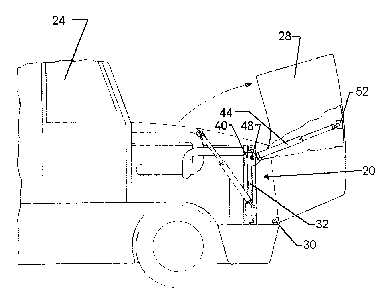
[00~3~ An actuator in accordance with the present invention is indicated
generally at 20 in
Figure 1. As shown, actuator 20 is installed in the engine compartment of a
truck 24 and is
operable to move an engine compartment closure, in this embodiment hood 28,
enclosing the
engine compartment of truck 24 between an open position, illustrated in the
Figure in solid
line, and a closed position illustrated in dashed line. Hood 28 is mounted to
truck 24 by a
suitable hinge mechanism 30 at the front end of the engine compartment of
truck 24 and by a
suitable latch mechanism, not shown, at the rear end of the engine
compartment.
[00~4~ As best seen in Figure 2, actuator 20 comprises a geared rack 32 which
is mounted
to truck 24 within the engine compartment. Preferably, each end of rack 32 is
affixed to a
suitable attachment point on truck 24, such as to the mount 36 for the
radiator in the engine
compartment.
[o0~5~ A traveler 40 moves along geared rack 32, as described below, and one
end of a
lift rod assembly 44 connects to a mount point 48 on traveler 40 and the other
end of lift rod
assembly 44 connects to a mounting point 52 on hood 28, as best seen in Figure
3.
[oois~ Preferably, lift rod assembly 44 comprises an upper rod 56 which is
received within
a lower rod 60. The relative position of upper rod 56 within lower rod 60, and
thus the overall
length of lift rod assembly 44, is maintained by a removable pin 64 which
extends through a
aperture in lower rod 60 and through one of a series of apertures in upper rod
56. As will be
apparent, the length of lift rod assembly 44 can easily pin altered by
removing pin 64, moving
upper rod 56 with respect to lower rod 60 until another aperture through upper
rod 56 aligns
with the aperture in lower rod 60 and then reinserting pin 64. It is
contemplated that actuator
20 can be employed as an after market option and the adjustability of the
overall length of lift
rod assembly 44 allows actuator 20 to be easily fit to a large range of
trucks. However, the
present invention is not limited to use with an adjustable length lift rod and
a rod with an
appropriate fixed length can also be employed.
[ooi~~ Traveler 40 and geared rack 32 are shown in more detail in Figure 4. As
illustrated,
traveler 40 includes a carriage 68 which has two idler wheels 72 and 76 which
engage the flat
side of geared rack 32 and a pinion gear 80 which engages the toothed side of
geared rack
32. Pinion gear 80 is driven by a DC motor 84 mounted to carriage 68 and, as
DC motor 84
rotates pinion gear 80 in a first direction, traveler 40 moves up gear rack 32
and, as DC motor
84 rotates pinion gear 80 in the opposite direction, traveler 40 moves down
gear rack 32.
Magna Ref: 703821 PRO 3 REV D Woodview Patent Services Ltd.
September 27, 2005 Bob Stratton / Woodview Ref: 2005-38
CA 02524114 2005-10-21
~oo~s] In the present embodiment, an electronics package 88 is also mounted to
carriage
68, although it will be apparent to those of skill in the art that electronics
package 88 can be
mounted to gear rack 32 or separately to a suitable mounting location within
the truck that
actuator 20 is installed in. Electronics controller 88 is supplied with DC
power from a cable 96
which is connected to a DC power source on the truck that actuator 20 is
installed on and
cable 96 is long enough to allow traveler 40 to move between the upper and
lower extremes
of gear rack 32.
fools] Electronics controller 88 is responsive to an operating switch 100,
which allows a
user to operate actuator 20 to open, close or stop hood 28. W hen switch 100
is moved to the
"open" position, electronics controller 88 supplies DC power to motor 84 to
move traveler 40
up gear rack 32. When switch 100 is moved to the "close" position, electronics
controller 88
supplies DC power to motor 84 to move traveler 40 down gear rack 32. When
switch 100 is
moved to the "stop" position, electronics controller 88 immediately removes
the power from
motor 84, whether or not hood 28 is fully opened or closed. This "stop"
function is provided to
allow a user to stop unsafe operation of actuator 20, which may occur due to a
person or
object being in the way of hood 28 or other unsafe condition.
X0020] Preferably, electronics controller 88 includes a current sensing
circuit, or other
sensor, which can detect if DC motor 68 stalls, which will occur when traveler
40 reaches
either extremity of geared rack 32, or when hood 28 abuts a person or object
preventing
further movement of hood 28.
~0021~ When a stall condition is detected, electronics controller 88 will
remove the DC
power from motor 84. If traveler 40 has reached an extremity of geared rack
32, the removal
of DC power from motor 84 completes the opening, or closing, of the hood 28.
If hood 28 has
abutted an object preventing further opening or closing of hood 28, removal of
the DC power
from motor 84 by electronics controller 88 serves as a safety precaution to
prevent damage to
hood 28 and/or injury to people.
~0022~ As will be apparent to those of skill in the art, after electronics
controller 88 has
detected a stall condition, reactivation of switch 100 will cause electronics
controller 88 to
reapply DC power to motor 84 to, depending upon the mode in which switch 100
was
activated, raise or lower traveler 40 until the next stall condition is
detected or until switch 100
is placed in the off position.
~oo2s) While electronics controller 88 preferably employs the described stall
detector, the
present invention is not so limited and any other suitable method of detecting
traveler 40
Magna Ref: 703821 PRO 3 REV D Woodview Patent Services Ltd.
September 27, 2005 Bob Stratton / Woodview Ref: 2005-38
CA 02524114 2005-10-21
6
reaching a movement extremity, such as limit switches, can also be employed.
Further, the
present invention is not limited to the use of a stall sensor for detecting
unsafe conditions,
such as hood 28 abutting an object, and any other suitable means such as known
ultrasonic
and/or radar-like systems for detecting such unsafe conditions, as would occur
to those of
skill in the art, can also be employed.
(0024] It is contemplated that switch 100 will be located in the passenger
compartment of
truck 24, preferably on the passenger side, to promote the convenient and safe
operation of
actuator 20. However, it is also contemplated that electronics controller 88
can also include a
wireless receiver 104, such as a radio or infrared receiver, allowing actuator
20 to be
operated from a portable transmitter 108, such as a key fob or the like,
either in addition to
from switch 100 or instead of from switch 100.
(0025] Another function of electronics controller 88 is in the mitigation of
backdriving of
motor 84 by hood 28. Specifically, as will be apparent to those of skill in
the art, when the
center of gravity of hood 28 moves over center (both when closing or opening
hood 28), the
weight of hood 28 can act to backdrive motor 84 which can result in hood 28
moving faster
than intended (or desired), resulting in damage to motor 84 and/or undesired
operation of
actuator 20. Accordingly, in a presently preferred embodiment of the present
invention
electronics controller 88 is operable to remove the supply of current to motor
84 and to either
inter-connect the current supply leads of motor 84 or to place a electrically
resistive element
in circuit therewith, such that motor 84 will act as a generator/brake to
avoid backdriving of
motor 84. A variety of methods can be employed by electronics controller 88 to
detect the
onset of overdriving, including using the above mentioned current sensing
circuitry to detect a
drop in the current being supplied motor 84, indicating that motor 84 is being
overdriven.
Alternately, the rotational speed of motor 84 can be monitored by electronics
controller 88,
etc.
(0026] While less preferred, a manual switch can be used in place of
electronics controller
88, allowing DC power to be applied to motor 84 in either of two polarities to
open or close
hood 28, although this requires the user to hold the manual switch in the
appropriate position
until hood 28 has been opened or closed and to release the manual switch when
the desired
position has been obtained. By locating the switch well away from hood 28,
this embodiment
can enforce a level of safety as when the operator is holding the switch to
maintain operation
of actuator 20, they will necessarily be out of the way of harm from movement
of hood 28.
Magna Ref: 703821 PRO 3 REV D Woodview Patent Services Ltd.
September 27, 2005 Bob Stratton / Woodview Ref: 2005-38
CA 02524114 2005-10-21
7
[002~~ A safety cover, comprising a front portion 112a and a rear portion 112b
is mounted
about carriage 68 and motor 84 and electronics controller 88 to prevent
unintentional access
to idler wheels 72 and 76 and pinion gear 80 and to motor 84 and electronics
controller 88.
[0028] Also shown if Figure 4 are mounting brackets 116 and 120 which are one
of the
suitable manners by which gear rack 32 can be mounted within the engine
compartment of
truck 24.
[oo2s~ As should now be apparent, as traveler 40 moves up gear rack 32, lift
rod assembly
44 acts between mounting point 48 on traveler 40 and mounting point 52 which
is attached to
hood 28, to move hood 28 to its open position. Figure 5 shows one possible
geometry of the
movement of mounting point 52 on hood 28 (not shown in the Figure), mounting
point 48 on
traveler 40 (not shown in the figure) and lift rod assembly 44 as traveler 40
is moved between
the bottom and the top of gear rack 32. As shown, hood 28 is pivoted about
hinge
mechanism 30, swinging hood 28 forward about hinge mechanism 30 to open hood
24 and
swinging hood 28 backward about hinge mechanism 30 to close hood 28.
[ooso] In the illustrated geometry, as hood 28 is opened by actuator 20, the
center of
mass of hood 28 will eventually move in front of hinge mechanism 30. At this
point, actuator
20 will effectively begin acting as a brake as the weight of hood 28 would
otherwise act to
rapidly pivot hood 28 about hinge mechanism 30 to open hood 28. Similarly, as
hood 28 is
closed by actuator 20, the center of mass of hood 28 will eventually move
behind hinge
mechanism 30 and, at this point, actuator 20 will effectively begin acting as
a brake as the
weight of hood 28 would otherwise act to rapidly pivot hood 28 about hinge
mechanism 30 to
close hood 28. Thus, in one part of each open or close operation, actuator 20
acts initially as
a prime mover to lift the weight of hood 28 and subsequently acts as a brake
to retard self-
movement of hood 28.
[oos~~ In the event of a failure of actuator 20, or a dead vehicle battery or
other problem
with the electrical supply to electronics controller 88, it is necessary that
the owner and/or
operator of truck 24 still be able to open hood 28 for necessary inspections
and/or
maintenance. In such a case, the owner and/or operator can reach pin 64 via
the wheel well
opening on truck 24 to remove pin 64 from lift rod assembly 44, thus allowing
hood 28 to be
opened, pulling upper rod 56 from lower rod 60. Once the defective battery or
other fault has
been repaired, the owner and/or operator of truck 24 can reinsert upper rod 56
into lower rod
60 and reinsert pin 64, thus re-enabling actuator 20.
Magna Ref: 703821 PRO 3 REV D Woodview Patent Services Ltd.
September 27, 2005 Bob Stratton / Woodview Ref: 2005-38
CA 02524114 2005-10-21
8
[oos2] It is contemplated that actuator 20 can relatively quickly move hood 28
between
open and closed positions. Further, it is contemplated that, while actuator 20
can be provided
as original equipment on truck 24, actuator 20 can also easily be fitted to
truck 24 as an after
market accessory. All that is needed in this later case is to appropriately
mount gear rack 32
within the engine compartment, attach mounting point 52 to an appropriate
location on hood
28, connect an appropriate supply of DC power to cable 96 and to install lift
rod assembly 44
between mounting points 48 and 52, with pin 64 inserted into the appropriate
aperture in
lower rod 60. Switch 100 can then be mounted in a desired location or portable
transmitter
108 can be used instead.
[ooss] Another embodiment of the present invention is illustrated in Figures 6
through 9.
In the Figures, an actuator in accordance with the present invention is
indicated generally at
200. In Figure 6, the truck hood 28 is shown in the closed position and, in
Figure 7, truck
hood 28 is shown in the opened position. As with the previous embodiment
described above,
truck hood 28 pivots about a suitable hinge mechanism 30 which works between
the frame of
the truck and hood 28 and hood 28 can be maintained in the closed position by
a latch 204,
or other suitable mechanism.
[0034] Again, as in the previously described embodiment, a lift rod 208
extends between a
pivot point 212, mounted to hood 28, and actuator 200, as is described in more
detail below.
Lift rod 208 can be an assembly, such as that described above with respect to
the
embodiment of Figures 1 through 5, such that the length of lift rod 208 can be
altered to
permit easy installation of actuator 200 as an after market item and/or which
can be
disconnected to allow manual opening or closing of the hood in case of failure
of actuator 200
or the vehicle's power system.
[ooss] The operation of actuator 200 is best understood with reference to
Figure 8. As
shown, actuator 200 includes a DC motor 216 to whose output shaft a pinion
gear 220 is
attached. DC motor 216 is mounted to an actuator mount 224, which is in turn
mounted to
the truck. A ring gear 228 is also mounted to actuator mount 224 via a
suitable bearing
mount (not shown) such that ring gear 228 is rotated about its center axis
when pinion gear
220 is rotated by DC motor 216.
[ooss] An actuator arm 232 is mounted to, and extends longitudinally from, the
center of
ring gear 228 ring and actuator arm 232 includes a mounting point 236 to which
one end of lift
rod 208 is pivotally attached.
Magna Ref: 703821 PRO 3 REV D Woodview Patent Services Ltd.
September 27, 2005 Bob Stratton / Woodview Ref: 2005-38
CA 02524114 2005-10-21
9
~003~] As should now be apparent to those of skill in the art, as DC motor 216
is supplied
with electrical current by an electronics controller (not shown), pinion 220
is rotated which, in
turn rotates ring gear 228. When the current supplied to DC motor 216 is of a
polarity which
causes ring gear 228 to be rotated, by pinion 220, in the direction indicated
by the arrow
labeled A, actuator arm 232 moves lift rod 208 such that hood 28 is moved
towards the
closed position illustrated in Figure 6.
~ooss] Conversely, when current is supplied to DC motor 216 with a polarity
which causes
ring gear 228 to be rotated, by pinion 220, in the direction indicated by the
arrow labeled B,
actuator arm 232 moves lift rod 208 such that hood 28 is moved towards the
open position
illustrated in Figure 7. Figure 9 shows the resulting geometry of actuator 200
and the range
of movement of actuator arm 232 can be seen.
X0039] As with the embodiment of Figures 1 through 5, the supply and control
of current to
DC motor 216 to start, stop and control operation of actuator 200 can be
accomplished in a
wide variety of manners. For example, a manually actuated switch (not shown)
similar to
switch 100 can be used to manually control actuator 200. A remote control,
such as an
infrared or radio transmitter, can also be used. Further, as described before,
electronics
control circuitry including a stall sensor, current sensing circuitry (not
shown), limit switches
240 and 244 (illustrated in Figure 9) or other sensing devices can be employed
to
automatically stop supplying current to DC motor 216 when hood 28 reaches its
fully closed
or fully open positions and/or to prevent overdriving of motor 216.
Further, such control circuitry can be used, as described previously, for
detecting
unsafe conditions, such as hood 28 abutting an object and removing the supply
of current to
DC motor 216. As will be apparent to those of skill in the art, any other
suitable means such
as known ultrasonic and/or radar-like systems for detecting such unsafe
conditions, as would
occur to those of skill in the art, can also be employed with the control
circuitry.
~004~] Figure 10 shows another embodiment of the present invention wherein
like
components to those illustrated in Figures 6 through 9 are indicated with like
reference
numerals.
~0o42] In the embodiment of Figure 10, actuator 300 includes a pinion gear 220
driven by
a DC motor (not shown in the Figure) as before. However, in this embodiment, a
drive disc
304 is mounted co-axially with ring gear 228 and actuator arm 232 is mounted
to drive disc
304. Both of drive disc 304 and ring gear 228 are mounted via bearings or
other suitable
means such that they can rotate independent of one another. A dampening
member, in this
Magna Ref: 703821 PRO 3 REV D Woodview Patent Services Ltd.
September 27, 2005 Bob Stratton / Woodview Ref: 2005-38
CA 02524114 2005-10-21
example compression springs 308, are mounted to act between ring gear 228 and
drive disk
304. As will now be apparent, when ring gear 228 is rotated by pinion gear
220, the resulting
torque is transferred to drive disc 304, and thus to lift rod 208, via the
springs 308. Springs
308 thus provide a dampening to actuator 300 to absorb shocks as the DC motor
of actuator
300 starts and stops and as hood 28 moves to and from over-center positions,
when opening
and closing.
~oo4s~ While the illustrated dampening member comprises springs 308, the
present
invention is not so limited and any suitable dampening member, such as one or
more blocks
of resilient material, can be employed as desired.
~0044~ Figure 11 shows an alternative construction for a lift rod assembly 400
to be used
with the present invention to provide a dampening and/or mechanism if desired.
Lift rod
assembly 400 comprises a lower member 404 and an upper member 408 and a
dampening
member, in this example a coil spring 412, which interconnects members 404 and
408. The
ends of coil spring 412 are captured by upper member 408 and lower member 404
such that,
when lift rod assembly 400 is in compression, coil spring 412 is in
compression, and when lift
rod assembly 400 is in tension, coil spring 412 is in tension. Lift rod
assembly 400 thus
provides a dampening capability to absorb shocks as the DC motor of an
actuator in
accordance with the present invention starts and stops and as hood 28 moves to
and from
over-center positions, when opening and closing. The present invention is not
limited to the
use of coil springs for the dampening member in lift rod assembly 400 and
other suitable
dampening members, such as resilient or elastomeric members or hydraulic or
gas springs
are examples of other dampening members that can be employed. Lift rod
assembly 400 can
be employed with actuator 20, actuator 200 or actuator 300, as desired.
[oo4s] Another embodiment of the present invention is illustrated in Figure 12
wherein like
components to those described above are indicated with like reference
numerals. In this
embodiment, actuator 500 includes a ring gear 504 which includes a pair of
longitudinally
extending pins 508 and 512, one extending from each side of ring gear 504.
[ooas] Ring gear 504 further includes a first torsion spring 516 and a second
torsion spring
520 each of which has a respective one end affixed to a part 524 of the frame
of the truck
and a respective other end which extends towards the periphery of ring gear
504 as shown.
[ooa~] First spring 516 is arranged such that, when hood 28 passes the over-
center point
when moving from the open position toward the closed position, pin 512 abuts
the free end of
first spring 516 which biases pin 512, and ring gear 504, away from the closed
position.
Magna Ref: 703821 PRO 3 REV D Woodview Patent Services Ltd.
September 27, 2005 Bob Stratton / Woodview Ref: 2005-38
CA 02524114 2005-10-21
1l
Similarly, second spring 520 is arranged such that, when hood 28 approaches
the open
position from the closed position, pin 508 abuts the free end of second spring
520 which
biases pin 508, and ring gear 504, away from the open position. By biasing
ring gear 504
with a respective one of first torsional spring 516 and second torsional
spring 520 during
respective portions of the travel range of hood 28, first torsional spring 516
and second
torsional spring 520 act as energy storage devices inhibiting the weight of
hood 28 from
overdriving the DC motor (not shown) and reducing the torque required to be
delivered by the
DC motor when starting to move hood 28 from either its fully open or fully
closed positions as
the DC motor is assisted by the biasing force which acts to counter the weight
of hood 28.
Thus, the size of the DC motor can be reduced, with a commensurate expected
cost saving
for actuator 500.
[ooas~ As will be understood by those of skill in the art, the present
invention is not limited
to the particular arrangement of torsional springs and pins, described above,
to differentially
bias ring gear 504 over its range of travel and it is contemplated that a wide
range of
alternative configurations and mechanisms will occur to those of skill in the
art.
[ooa9] Figure 13 shows another differentially biased embodiment of an actuator
600 in
accordance with the present invention wherein like components to those
described above are
indicated with like reference numerals. In this embodiment, the shaft 604 on
which ring gear
228 rotates is fixed with respect to housing 224 and arm 232 includes a hub
with a bearing
surface to allow arm 232, and ring gear 228 which is mounted to arm 232, to
rotate on shaft
604.
[ooso~ Shaft 604 is surrounded by a coil spring 608 and one end of spring 608
is fixed to
ring gear 288 and the other end of spring 608 is fixed to housing 224, or to a
member (not
shown) in the engine compartment of the vehicle. Preferably, coil spring 608
is fabricated
and/or installed on actuator 600 such that its "at rest" position (wherein
there are substantially
no torsional forces on spring 608) corresponds to the position of ring gear
228 when the
center of gravity of hood 28 is substantially over the mounting point 236,
referred to herein as
the centered position. Thus, spring 608 is tensioned in a first direction when
hood 28 moves
past the centered position towards the closed position of hood 28 and is
tensioned in an
opposite direction when hood 28 moves past the centered position towards the
open position
of hood 28.
[oos~~ By tensioning spring 608 in the corresponding direction as hood 28 is
moved from
the centered position, spring 608 serves as an energy storage device,
preventing overdriving
Magna Ref: 703821 PRO 3 REV D Woodview Patent Services Ltd.
September 27, 2005 Bob Stratton / Woodview Ref: 2005-38
CA 02524114 2005-10-21
12
of DC motor 216 by the weight of hood 28. Further, the resulting biasing force
exerted by
spring 608 on ringer gear 228 assists DC motor 216 to move hood 28 from the
open and
closed positions towards the centered position.
X0052) If packaging constraints or other considerations prevent spring 608
from being
arranged to act in both tension and compression, one end of spring 608, such
as the end
which was previously described as being fixed to ring gear 228, can instead be
arranged to
abut a feature (not shown, such as a boss or pin on ring gear 228 or on
housing 224, etc.)
such that spring 608 only biases ring gear 228 between the closed position and
the centered
position, after which point this end of spring 608 is disengaged and free to
rotate about shaft
604. As will now be apparent to those of skill in the art, in this
configuration spring 608 will
only act as an energy storage and biasing device between the closed and
centered positions.
~oos3) However, if in this configuration it is desired to provide some energy
storage
mechanism during movement of hood 28 between the centered position and the
open
position, another mechanism, such as a second spring or the resilient lift rod
(described
below) can be employed.
~oosa) As another alternative, in the embodiment of Figure 13 coil spring 608
can instead
be configured with a noose ring 612, best seen in Figure 14, to provide a
dampening force on
the hub of arm 232 as arm 232 rotates to close hood 28. Specifically, in this
configuration, as
spring 608 is tensioned when ring gear 228 rotates to close hood 28, the
diameter of coil
spring 608 about shaft 604 is reduced and this reduced diameter exerts a
compressive force
on noose ring 612 and, in turn, on the hub of arm 232. Noose ring 612 is
fixed, by any
appropriate means, with respect to housing 224 such that it cannot rotate and
thus the
compressive force on noose ring 612 results in a frictional dampening force
being exerted on
arm 232 as it rotates with ring gear 228 to close hood 28. This frictional
dampening force
assists in preventing overdriving of motor 216 by the weight of hood 28 as
hood 28 is closed.
[0055] It is contemplated that the design of some engine compartments may
limit the
positions in which an actuator in accordance with the present invention can be
installed and
that the resulting installation may result in a less than optimal operating
geometry for the
actuator. In such cases, it is contemplated that it may be useful to employ a
lift rod assembly
whose length can vary, during opening and closing of the hood 28, between a
first shorter
length and a second longer length. Such a lift rod assembly can be constructed
of two
telescopically engaged members as before, except in this circumstance a pin,
similar to pin
64 described above, would be inserted into a bore through one member and ride
in a slot in
Magna Ref: 703821 PRO 3 REV D Woodview Patent Services Ltd.
September 27, 2005 Bob Stratton / Woodview Ref: 2005-38
CA 02524114 2005-10-21
13
the other member. As will be apparent, the first shorter length and second
longer length are
established as the pin abuts a respective end of the slot.
(oo5s~ It is further contemplated a resilient member, for example a coil
spring, can be
arranged in the lift rod assembly to obtain a resilient lift rod assembly
wherein the resilient
member acts between the two telescopically engaged members such that energy is
stored in
the resilient member when the rod is compressed or tensioned. By compressing
and/or
tensioning the resilient lift rod assembly, both a dampening force and a motor
assist force can
be provided.
(005~~ As mechanical movement of a moveable closure, such as a truck hood, can
raise
some safety concerns, the present invention preferably offers several safety
features. As
mentioned above, the control circuitry current to the DC motor of actuators in
accordance with
the present invention can include stall detector circuitry, such as current
sensors or rotational
movement detectors, to provide object collision avoidance capability, wherein
current is
removed from the DC motor if a collision between the truck hood and an object
is detected.
(oo5s) Also, actuators in accordance with the present invention can include an
piezeoelectric buzzer or other sound generating device which operates to
provide an audible
warning that the actuator is operating and the moveable closure is moving.
Further, if the
actuators in accordance with the present invention include a remote control,
such as a radio
or infrared remote, the remote control can be configured to operate in a
failsafe mode
wherein the button on the remote must be continually pressed to maintain
operation of the
actuator. For example, to open the truck hood, the user must press and hold
the button on
the remote corresponding to the open function until the hood is fully open.
Releasing this
button at any time during the opening operation causes the supply of current
to the DC motor
to be withdrawn, stopping operation of the actuator until the button is again
pressed and held.
[0059] Alternatively, the remote can operate such that the user pressed a
button
corresponding to the desired operations (i.e. - open or close the hood) and
the actuator will
automatically perform the requested operation. If the user presses any button
on the remote
prior to completion of the requested operation, the control circuitry of the
actuator interprets
this signal as an emergency stop command and causes the supply of current to
the DC motor
to be withdrawn, stopping operation of the actuator.
(ooso~ In this latter case, wherein a second button press is interpreted as an
emergency
stop command, it is important to have a high level of confidence that the
remote will continue
to operate properly throughout the requested opening or closing operation.
Accordingly, the
Magna Ref: 703821 PRO 3 REV D Woodview Patent Services Ltd.
September 27, 2005 Bob Stratton / Woodview Ref: 2005-38
CA 02524114 2005-10-21
14
remote preferably operates to determine the condition of its battery power
supply and, when a
button is pressed on the remote to signal the desired start of an opening or
closing operation,
the remote determines if its battery condition exceeds a predefined safe
operating level.
If the predefined safe operating level is met, it is assumed that the battery
power
supply is in a sufficient condition to safely and reliably operate throughout
the requested open
or close operation and the remote transmits the appropriate command to the
control circuitry
on the truck to commence the requested operation.
~oos2) If the predefined safe operating level is not met, the remote then
compares the
condition of its battery power supply to a predefined second level. If the
determined battery
condition is less than the predetermined safe operating level but greater than
the second
predetermined level, the remote can provide an indication of the determined
state of its
battery power supply to the operator, for example by flashing a warning LED on
the remote
and the remote transmits to the control circuitry both the appropriate command
and a signal
indicating the status of its battery power supply. In response to the receipt
of the two signals
from the remote, the actuator control circuitry commences the requested
opening or closing
operation and also provides another indication to the user that the state of
the battery supply
in the remote may be unsafe. This other indication can be any appropriate
signal and, in a
presently preferred embodiment, is provided by altering the sound from the
above-mentioned
piezeoelectric buzzer to provide an audible warning to the user that the
battery of the remote
should be replaced.
~oos3~ If the determined battery condition is less than the second
predetermined level, the
remote will send a signal to the control circuitry of the actuator indicating
that condition and
the actuator can then provide a fault code to the user, for example by beeping
the
piezeoelectric buzzer three times, to indicate that the power supply of the
remote is not in a
safe operating condition and must be replaced before the actuator will
operate. At this point,
the user can either replace the batteries in the remote or manually open or
close the hood, as
described above.
~oosa) As another preferred safety feature, the control circuitry will operate
the above-
mentioned stall sensors such that the current levels which represent a
detected stall condition
are learned by the actuator for each installation. Specifically, as each
installation of an
actuator in accordance with the present invention will require the motor to
produce a different
peak torque over an opening and closing operation, due to a variety of truck-
specific factors
such as the weight of the hood, the installation geometry of the lift rod and
hood pivot points
Magna Ref: 703821 PRO 3 REV D Woodview Patent Services Ltd.
September 27, 2005 Bob Stratton / Woodview Ref: 2005-38
CA 02524114 2005-10-21
etc., it is difficult to predefine appropriate maximum current levels at which
the stall sensor
should operate.
(ooss] Accordingly, the actuator can be shipped with these maximum current
levels set to
a selected high level, for example at a point just below the current level at
which damage will
occur to DC motor. Once the actuator is installed on the vehicle, these pre-
selected high
levels will be used as the stall detection levels, but the control circuitry
will monitor the actual
measured maximum current levels experienced by the DC motor during a given
number (e.g.
twenty) of opening and closing operations. These measured maximum current
levels, plus a
small margin, are then used as the current levels which indicate a stall.
Thus, an actuator in
accordance with the present invention can learn appropriate stall level
currents for its
particular installation.
The present invention provides a truck hood actuator which, operating via a
gear
rack and DC motor-powered traveler or a pinion and ring gear mechanism, can
operate more
quickly than a hydraulic actuator, or a worm or screw gear actuator. Further,
by employing
the disclosed gear rack and traveler or pinion and ring gear, the actuator of
the present
invention can be readily employed and installed as an after market accessory
or as OEM
equipment at a lower cost than a hydraulic or other, more complex, actuators.
~oos~~ The above-described embodiments of the invention are intended to be
examples of
the present invention and alterations and modifications may be effected
thereto, by those of
skill in the art, without departing from the scope of the invention which is
defined solely by the
claims appended hereto.
Magna Ref: 703821 PRO 3 REV D Woodview Patent Services Ltd.
September 27, 2005 Bob Stratton / Woodview Ref: 2005-38