Note: Descriptions are shown in the official language in which they were submitted.
CA 02524823 2005-10-31
1 10029P00070
DIRECT SIDEWALL VENT SYSTEM
BACKGROUND OF THE INVENTION
FIELD OF THE INVENTION
This invention relates to vent systems forfuel-burning appliances and, more
particularly, to a direct vent system that communicates between an internal
space,
within which the appliance is located, and the external atmosphere, through a
vertically extending sidewall.
BACKGROUND ART
Fuel-burning appliances are commonly equipped with direct sidewall vent
systems. Typically, concentric conduits communicate between the appliance and
an external atmosphere generally in a horizontal direction through an outside,
vertically extending sidewall. An inner conduit communicates combustion gases
from the appliance to the external atmosphere. An annular passage between the
inner conduit and a surrounding conduit communicates makeup air from the
external atmosphere to the appliance.
Ideally, to optimize operation and efficiency of the fuel-burning appliance,
air flow volume to, and pressure in, the appliance burner are maintained
within
specific ranges. Reduced air flow to the burner may cause sooting, which is
detrimental to the appliance and also produces pollutants that are undesirably
discharged to the atmosphere and potentially to against the interior and
exterior
of the building within which the appliance is located.
CA 02524823 2005-10-31
2 10029P00070
The type and location of the intake for makeup air and its relationship to the
subjacent surface, combustion gas outlet, and wall upon which the vent system
is
mounted, are critical in the design of such systems to maintain adequate air
flow.
Myriad different makeup air intakes have been devised in the industry. It is
known,
for example, to provide a makeup air intake at one side, or opposite sides, of
the
conduits. Operation of certain of these systems may be adversely affected by
atmospheric wind conditions.
Environmental winds may adversely affect other vent designs as well. High
winds tend to block the discharge of combustion gas. A pressure buildup may
result in the combustion chamber that slows down air flow to the burner. This
may
result in sooting, with the attendant disadvantages, noted above.
More commonly, the makeup air is drawn from a region at the bottom of the
external portion of the vent system. These bottom located intakes have some of
their own inherent disadvantages.
Commonly, those installing direct vent systems will locate the external
portion of the vent system in close proximity to the ground, either at the
behest of
the building owner, for purposes of aesthetics, or for reasons dictated by the
building geometry or convenience and ease of installation. Manufacturers of
these
vent systems typically will specify a minimum clearance between the external
portion of the vent system and the subjacent ground. Even within these
specifications, there are some inherent problems that are commonly
encountered.
First of all, an accumulation of snow or debris may effectively reduce the
clearance between the makeup air intake and the ground. The intake may be
partially, or in a worse case altogether, blocked so that the required air
flow does
not occur at the combustion chamber.
CA 02524823 2005-10-31
3 10029P00070
Even if the clearance is within manufacturers' specifications, there is also
the possibility that atmospheric winds may interact with the ground and
surrounding structures to produce undesired pressure buildup at the makeup air
intake.
Further, the discharged gases, and potentially pollutants, entrained therein,
may be redirected at the subjacent surface so as to be recirculated by being
drawn
back into the makeup air intake. At low mounting heights, the makeup air
intake
is also prone to picking up debris that may be elevated thereto by winds
and/or the
discharging combustion gases. This debris may be detrimentally recirculated to
the appliance.
Heretofore, in the interest of facilitating installation, or addressing
aesthetic
concerns, building owners have mounted the external vent components in close
proximity to the ground, which has caused them to have to contend with the
above-mentioned problems associated with conventional vent systems; notably
variations in efficiency of the appliance operation, temporary flame-outs,
sooting,
etc. The industry continues to seek out designs to address some or all of the
above problems.
SUMMARY OF THE INVENTION
In one form, the invention is directed to a direct sidewall vent system
between a fuel-burning appliance in a first space and an external atmosphere,
through a wall between the first space and external atmosphere. The direct
sidewall vent system has a wall assembly that defines a first passage for
communicating combustion gas generated through operation of the fuel-burning
appliance to a first outlet through which the combustion gas is communicated
to
the external atmosphere. The wall assembly further defines a second passage
for
CA 02524823 2005-10-31
4 10029P00070
communicating makeup air from the external atmosphere to the fuel-burning
appliance in the first space. The direct sidewall vent system further has an
external portion that is situated within the external atmosphere and at which
the
first outlet is located. The external portion of the direct sidewall vent
system has
a top, a bottom, and spaced sides. The external portion of the direct sidewall
vent
system has a first inlet within the external atmosphere through which makeup
air
from the external atmosphere is communicated to the second passage. The first
inlet is situated to draw makeup air from the external atmosphere primarily
from
a location above the first outlet.
In one form, the wall assembly has a vent pipe that has a central axis and
defines at least a part of the first passage. The first inlet is situated to
draw
makeup air from the external atmosphere primarily from a location above the
central axis of the vent pipe.
In one form, the second passage has a central axis and the first inlet is
situated to draw makeup air from the external atmosphere from a location above
the central axis of the second passage.
In one form, the wall assembly has substantially concentric cylindrical walls
between which at least a part of the second passage is defined.
The first inlet may be situated substantially fully above the central axis of
the vent pipe and/or central axis of the second passage.
In one form, the wall assembly has a funnel-shaped portion that has a
progressively decreasing cross-sectional area from an upstream end of the
first
passage towards a) a downstream end of the first passage and b) the first
outlet
through which combustion gas is jetted to the external atmosphere.
CA 02524823 2005-10-31
10029P00070
The funnel-shaped portion may be oriented to jet combustion gas in a
direction angularly downwardly and away from the wall between the first space
and
external atmosphere.
In one form, the wall assembly comprises a shroud that defines the first
5 inlet.
The first inlet may open downwardly.
In one form, the shroud has a funnel-shaped portion in which incoming
makeup air is expanded.
In one form, the wall assembly defines a surface below the first inlet that is
inclined upwardly towards the first inlet so as to deflect air directed at the
wall
between the first space and the external atmosphere towards the first inlet..
The first outlet may open downwardly.
A flow inducing mechanism may be provided for at least one of a) inducing
flow of combustion gas through the first passage and b) inducing flow of
makeup
air through the second passage.
The direct sidewall vent system may be provided in combination with a fuel-
burning appliance within a first space bounded by a wall through which the
direct
sidewall vent system extends.
The wall assembly niay be made from stainless steel.
In one form, the wall assembly has a second pipe surrounding the vent pipe
and between which at least a part of the second passageway is defined. The
second pipe has a top and bottom and makeup air through the first inlet is
introduced to the second passage primarily through the bottom of the second
pipe.
The invention is further directed to a direct sidewall vent system between
a fuel-burning appliance in a first space and an external atmosphere through a
wall
between the first space and external atmosphere. The direct sidewall vent
system
CA 02524823 2005-10-31
6 10029P00070
has a wall assembly that defines a first passage for communicating combustion
gas generated through operation of the fuel-burning appliance to a first
outlet
through which the combustion gas is communicated to the external atmosphere.
The wall assembly defines a second passage for communicating makeup air from
the external atmosphere to the fuel-burning appliance in the first space. The
direct
sidewall vent system has an external portion that is situated within the
external
atmosphere and at which the first outlet is located. The external portion of
the
direct sidewall vent system has a top, a bottom, and spaced sides. The
external
portion of the direct sidewall vent system has a first inlet within the
external
atmosphere through which makeup air from the external atmosphere is
communicated to the second passage. The first inlet is situated to draw makeup
air from the external atmosphere primarily from a location at the top of the
external
portion of the direct sidewall vent system.
The invention is further directed to a method of venting a fuel-burning
appliance in a first space through a vertical sidewall between the first space
and
an external atmosphere. The method includes the steps of: providing a vent
system having a wall assembly that defines first and second passages with one
of the first and second passages having a central axis that extends through
the
vertical sidewall; operating the fuel-burning appliance and thereby producing
combustion gas; causing the combustion gas to be directed through the first
passage and discharge through a first outlet to the external atmosphere; and
causing makeup air to be directed from the external atmosphere through an
inlet
that is in communication with the second passage and from the inlet primarily
downwardly towards the cental axis of the one of the first and second passages
for delivery through the second passage to the fuel-burning appliance.
CA 02524823 2005-10-31
7 10029P00070
The invention is further directed to a method of venting a fuel-burning
appliance in a first space through a vertical sidewall between the first space
and
an external atmosphere. The method includes the steps of: providing a vent
system having a wall assembly that defines first and second passages with one
of the first and second passages having a central axis that extends through
the
vertical sidewall; providing a vent system having a wall assembly that defines
first
and second passages, with one of the first and second passages having a
central
axis that extends through the vertical sidewall, and that has an external
portion
exposed to the external atmosphere and having a top, bottom, and spaced sides;
causing the combustion gas to be directed through the first passage and
discharge
through a first outlet to the external atmosphere; and causing makeup air to
be
directed from the external atmosphere through an inlet primarily at the top of
the
external portion of the vent system for communication through the second
passage to the fuel-burning appliance.
BRIEF DESCRIPTION OF THE DRAWINGS
Fig. 1 is a schematic representation of a direct sidewall vent system,
according to the present invention, operatively assembled through a vertically
extending sidewall to communicate between a fuel-burning appliance and the
external atmosphere through the sidewall;
Fig. 2 is a view as in Fig. 1 wherein further detail of the vent system is
shown in schematic form;
Fig. 3 is an exploded, perspective view of one specific exemplary form of
the vent system in Figs. 1 and 2;
Fig. 4 is a side elevation of the vent system in Fig. 3; and
Fig. 5 is a perspective view of the vent system in Figs. 3 and 4.
CA 02524823 2005-10-31
8 10029P00070
DETAILED DESCRIPTION OF THE DRAWINGS
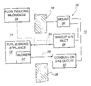
In Figs. 1 and 2, a direct, sidewall vent system, according to the present
invention, is shown schematically at 10 in association with a fuel-burning
appliance
12. The fuel-burning appliance 12 is not limited in nature and is shown
schematically to encompass any appliance that operates through combustion of
a fuel and requires discharge of combustion gases. The fuel-burning appliance
12 is provided within a space 14, typically a room of a building, separated
from the
external atmosphere 16 by a vertically extending sidewall 18.
The vent system 10 has a wall assembly, described in detail below, that
defines a first passage 20 for communicating combustion gas generated through
operation of the fuel-burning appliance 12 to an external combustion gas
outlet 22,
through which the combustion gas is communicated to the external atmosphere
16. The wall assembly further defines a second passage 24 for communicating
makeup air from the external atmosphere 16 to the fuel-burning appliance 12 in
the space 14. An external portion of the vent system 10 has a makeup air inlet
26
within the external atmosphere 16 through which makeup air from the external
atmosphere 16 is communicated to the second passage 24. The external portion
of the vent system 10 additionally defines the combustion gas outlet 22 and is
secured at an external surface 28 of the sidewall 18 through an appropriate
mount
30.
The fuel-burning appliance 12 may have a blower 32 that directs
combustion gas from the fuel-burning appliance 12 through the first passage 20
to and through the combustion gas outlet 22 to the external atmosphere 16.
Makeup air from the external atmosphere 16 is drawn in through the makeup air
inlet 26 and conveys to and through the second passage 24 to the fuel-burning
appliance 12. An optional flow inducing mechanism 34 may be provided at an
CA 02524823 2005-10-31
9 10029P00070
internal or external location to pressurize makeup air moving in the second
passage 24 back to the fuel-burning appliance 12. However, the present
invention
makes possible an adequate flow of makeup air to the fuel-burning appliance 12
without such a mechanical assist requirement.
The vent system 10 is shown schematically at 10 in Figs. 1 and 2 to
encompass virtually unlimited different configurations of wall structure.
Regardless
of the configuration, the invention contemplates that the makeup air inlet 26
draws
makeup air from the external atmosphere 16 primarily from an upper location on
the external portion of the vent system 10, preferably above the combustion
gas
outlet 22. Details of one exemplary configuration for the vent system 10 will
now
be described with respect to Figs. 3-5, with it being understood that this
particular
configuration is exemplary in nature only.
The aforementioned wall assembly is shown on the vent system 10 at 36.
The wall assembly 36 consists of a vent pipe 38, with a central axis 40, that
defines a part of the first passage 20 between the blower 32 on the fuel-
burning
appliance 12 and the combustion gas outlet 22 on the external portion 42 of
the
vent system 10. A downstream end 44 of the vent pipe 38 is suitably secured
within an opening 46 defined in a flat plate 48.
A wall 50 is cantilevered outwardly from the plate 48 and defines a flat
surface 52 that slopes downwardly from the bottom of the opening 46. A shroud
54 has a wall 56 with an open bottom 58 and an open end 60. With the end 60
placed against the flat plate 48, the opening 46 and wall 50 reside within a
chamber 62 bounded cooperatively by the wall 56 and flat plate 48.
With the shroud 54 secured to the flat plate 48, a sloping portion 64 of the
shroud wall 56, spaced side portions 66, 68 on the shroud wall 56, and the
wall 50
projecting from the flat plate 58, cooperatively define a funnel-shaped
portion of
CA 02524823 2005-10-31
10029P00070
the wall assembly 36 that causes discharging combustion gas to be jetted
generally in the direction of the arrow 70 in Fig. 4 to the external
atmosphere 16,
downwardly and away from the sidewall 18 upon which the vent system 10 is
mounted. As seen in Fig. 4, the sloping portion 64 of the shroud wall 56 has
an
5 inside surface 72 that faces the surface 52 on the wall 50 and bounds a
portion of
the first passage 20 within the funnel-shaped portion of the wall assembly 36.
The
surface 52 is at an angle 0 to horizontal, with the surface 72 at an angle 01
to
horizontal, with 81 being greater than 0. The angle 0, 01 may be on the order
of
45 , but could vary considerably from 45 . Accordingly, the cross-sectional
area
10 of the portion of the first passage 20 within the shroud 54 progressively
decreases
towards the downstream end of the first passage 20 and the outlet 22. Through
this arrangement, the aforementioned jetting action is produced that propels
the
combustion gases away from the sidewall 18 to prevent exposure of the gases to
the sidewall 18 as might leave unsightly residue thereon. This jetting action
also
reduces the tendency of the combustion gases to recirculate into the second
passage 24 through the makeup air inlet 26, as described in greater detail
hereinbelow. The flat plate 48 projects to below the outlet 22 to deflect
discharging combustion gases and shield the wall 18 from exposure thereto.
A hood 74, having the same general configuration as the shroud 54, but
larger in dimension, is mounted against the flat plate 48 so that the shroud
54
resides substantially fully within a chamber 76 bounded by the hood 74. In
addition to otherfunctions, described below, the hood 74 shields the userfrom
the
surfaces on the shroud 54 that become heated in use.
The shroud 54 and hood 74 are provided with peripheral flanges 78, 80,
respectively, which are suitably secured to the flat plate 48, as by separate
fasteners, welding, or the like.
CA 02524823 2008-12-01
11
A second pipe 82, with a diameter larger than the diameter of the vent pipe
38, surrounds the vent pipe 38 to be in concentric relationship therewith so
that an
annular space 84 is defined between the pipes 38, 82. The annular space 84
defines part of the second passage 24 for communicating makeup air from the
extemal atmosphere 16, drawn in at the inlet 26, to the fuel-burning appliance
12.
A flanged, upstream end 86 of the second pipe 82 is secured suitably to a side
88
of the flat plate 48 facing oppositely to the direction faced by the surface
89 to
which the shroud 54 and hood 74 are mounted.
A spacing frame at 90 is mounted to a flat plate 92 having the same,
generally squared shape as shown for the flat plate 48. The flat plate 92
defines
part of the mount 30, through which the vent system is secured to the sidewall
18.
The spacing frame 90 consists of contiguous bottom and spaced side frame parts
94 and 96, 98, respectively. The frame parts 94, 96, 98 have the same width
dimension W and are flanged to facilitate their attachment to the flat plates
48, 92,
by any suitable means, so that the frame parts 94, 96, 98 maintain the flat
plates
48, 92 together and spaced apart a distance equal to the width W.
A shroud 100 is attached through at least one flange 102 to the flat plate
92 and resides between the frame parts 96, 98. The shroud 100 and frame parts
94, 96, 98 cooperatively extend continuously around a chamber 104 between the
flat plates 48, 92. The shroud 100 extends further from the flat plate 92 than
the
frame parts 94, 96, 98, with the additional extension having an inclined wa!l
portion
106 that vertically overlies on inclined outer surface 108 of the hood 74 in
vertically
spaced relationship thereto. The iriside surface 110 of the wall portion 106
of the
shroud 100, and facing hood surface 108, may be substantially parallel or may
converge in a downstream direction over a portion of the second passage 24
defined by these surfaces. The surface 108 axially coincides with the central
axis
of the vent pipe 38 and, as depicted, blocks flow of air in an axial direction
directly
into the first passage 20. With the shroud 100 projecting, as seen most
clearly
CA 02524823 2005-10-31
12 10029P00070
in Fig. 4, the shroud 100 acts as an air scoop for funnelling atmospheric air
through the inlet 26 into the passage 24. The angles of the surfaces 108, 110
may
be on the order of 45 . However, these angles might vary considerably from 45
.
In windy conditions, air moving in the direction of the arrows 112 encounters
the hood surface 108 and is progressively bent upwardly to move into the inlet
26
and is thereafter funneled into the chamber 104 wherein it expands. The air in
the
chamber 104 communicates radially through a series of openings 112 through the
second pipe 82 and into the annular space 84 for delivery back to the fuel-
burning
appliance 12. The openings 112 are shown as circularwith an exemplary diameter
on the order of one inch. The openings 112 could have different sizes, shapes,
and locations around the periphery of the pipe 82. One or more larger holes
could
be utilized in place of the openings 112 shown.
With this arrangement, the makeup air is drawn from the external
atmosphere 16 through the makeup air inlet 26 in the region at the top of the
external portion 42 of the vent system 10 above the combustion gas outlet 22.
The locations of the inlet 26 and outlet 22 are not limited to precisely what
is
shown in Figs. 3-5. Preferably, the makeup air is drawn from the external
atmosphere from a location located above the central axis 40 for one of the
passages 20, 24. In this case, the central axes for the passages 20, 24 are
coincident.
As seen in Figs. 3-5, the makeup air inlet 26 is situated fully above the
central axis 40. It is preferred that if not located entirely above the
central axis, the
makeup air inlet 26 be located so that the makeup air is drawn from the
external
atmosphere 16 primarily from a location above the central axis 40. As shown,
and
most preferably, the makeup air is drawn primarily from a location at the top
of the
external portion 42 of the vent system 10.
CA 02524823 2005-10-31
13 10029P00070
In operation, as the fuel-burning appliance 12 is operated, combustion gas
is produced. Through the blower 32, and/or by reason of a temperature
differential, the combustion gas is caused to be directed through the first
passage
20, and more particularly initially through the vent pipe 38, through the
shroud 54
and to and through the outlet 22.
The makeup air enters the downwardly opening inlet 26 and expands into
the chamber 104 from where it communicates through the openings 112 into and
through the annular space 84 to the fuel-burning appliance 12.
By reason of the top location of the makeup air inlet 26, and the jetting of
the combustion gas from the outlet 22, there is potentially little
recirculation of the
combustion gas as makeup air. The bottom frame part 94 has a series of
slots/openings 114 therethrough which allow drainage of any accumulated
condensation and also provide an escape route for other foreign matter that
may
have migrated into the chamber 104. With the pipe openings 112 located at the
bottom region of the pipe 82, any foreign matter that enters the chamber 104,
as
via the shroud, may drop against the periphery of the pipe 82. By reason of
there
not being openings in the top region of the pipe 82, this matter tends to
slide
guidingly down the pipe to against the bottom frame part 94 from where it may
discharge through the slits/openings 114. Of course, the invention
contemplates
that openings through the pipe 82 may be provided at any peripheral location
thereon. However, such a design would generally be more prone to causing
entrainment of foreign matter into the makeup air supply communicated to the
fuel-
burning appliance 12.
In calm environmental conditions, system designs are normally such that
the makeup air is drawn into the fuel-burning appliance 12 in adequate volume.
Under windy conditions, the wind load tends to produce a pressure block at the
CA 02524823 2005-10-31
14 10029P00070
outlet 22. As a result, a burner on the fuel-burning appliance 12 may be
unable to
achieve complete combustion whereupon sooting may occur. Under these windy
conditions, the inventive design causes the impinging air to be funneled under
pressure into the inlet 26 and through the second passage 24 to the fuel-
burning
appliance 12. With the pressurized makeup air, cleaner combustion in the fuel-
burning appliance 12 may result.
Accordingly, with the described design, the external portion 42 of the vent
system 10 can be placed in close proximity to the subjacent ground at the
sidewall
18 and may, at this lower height, still be capable of drawing in adequate
volumes
of clean makeup air without substantial fear of flame-out of the burner or
sooting
commonly encountered with significant intake losses. This facilitates
installation
by allowing installers to work at comfortable heights. Fewer installation
problems
and errors may result. This also places the external portion 42 of the vent
system
10 below normal sight lines.
For purposes of integrity, and resistance to corrosion, the components of
the wall assembly 36, and particularly those that are exposed to the
combustion
gases and the elements in the external atmosphere 16, may be made from
stainless steel.
An optional third pipe 116, as shown in Fig. 4, may reside between the vent
and second pipes 38, 82, respectively, in concentric relationship therewith.
Through this arrangement, an annular space 118 is defined between the pipes
38,
82. The space 118 performs an insulating function to minimize heat exchange in
the event there are significant temperature differentials between the
departing
combustion gases and the incoming makeup air from the external atmosphere 16.
It is also contemplated that the vent pipe 38 can be made as a single piece.
Prior systems generally use a short stub pipe in the installation process. By
using
CA 02524823 2005-10-31
15 10029P00070
a single pipe construction, the likelihood of a leak into and from the first
passage
20 is minimized.
High temperature silicone RTV sealant may be used at critical connections,
such as between the downstream end 44 of the vent pipe 38 and the flat plate
48.
This minimizes the likelihood of recirculation at this and other locations.
The use
of a flange 120 on the downstream end 44 of the vent pipe 38 may further
facilitate
maintenance of the integrity of the connection of the vent pipe 38 and flat
plate 48.
The foregoing disclosure of specific embodiments is intended to be
illustrative of the broad concepts comprehended by the invention.