Note: Descriptions are shown in the official language in which they were submitted.
CA 02524923 2005-09-16
WO 2004/087543 PCT/IT2003/000188
DEVICE FOR STORAGE AND FEEDING OF PRODUCTS
Technical field
The present invention concerns a device for the accumulation and
s release of products disposed in ranks, in particular for feeding packaging
lines
for such products, according to the preamble of main claim No. 1.
Technological backgiround
Devices of the aforesaid type are widely used in packaging lines for
confectionery products, such as chocolate bars, biscuits or others of similar'
to type, in which such products are moved, on conveying lines, disposed in
ranks
or groups of ranks spaced from one another (by ranks there are meant in the
present context rows of aligned products, in which the rows are disposed
perpendicularly to the direction of advance of the products). Between these
conveying lines and the packaging machines there is typically interposed a
is storage unit for the products to permit regular feeding at a predetermined
and
uniform rhythm of the packaging machine, and thus to render said feeding
independent of the speed and variations in the flow of the incoming ranks.
With such storage units it is therefore possible to feed efficiently
different automatic packaging lines having speeds and feeding rhythms
zo programmed according to the type of product being dealt with.
Typically, such storage units comprise a magazine within which a
plurality of container elements is supported and conducted in series along a
path which optimizes the storage capacity. In general, the containers are
regularly spaced from one another at a predetermined pitch and each
2s comprises a plurality of shelves capable of supporting and containing
respective ranks of products. The provision of one or more conveyor chains
on which the containers are secured at a regular pitch is typical.
1
CA 02524923 2005-09-16
WO 2004/087543 PCT/IT2003/000188
The slide path of the chain is further selected such that each container
is conducted in sequence to the receiving opening for loading onto each of its
shelves one or more ranks of products coming into the storage unit and, at the
same time, a previously loaded container is conducted, by the effect of
movement of the chain, to the delivery opening for the release of the products
leaving the storage unit.
Storage units of this type normally extend in height and provide a
vertical ascending section of the chain for loading the containers in sequence
through the receiving opening and a descending vertical section of the chain
to for positioning the containers at the delivery opening and consequently
unloading the products from the storage unit. These sections are part of the
overall path, which may furthermore have a certain number of bends or
returns having the function of maximizing the number of containers (and
therefore of products) that can be accumulated within the storage unit.
is A limit to be encountered in the known storage devices having the
aforesaid characteristics lies in the fact that the distance between the last
support shelf of one container and the first shelf of the container following
it is
generally different from the pitch existing between adjacent shelves of the
same container. This makes it necessary to move the chain at different
2o speeds in order to guarantee the same loading rhythm when passing from the
last shelf of one container to the first shelf of the following container,
both in
the loading phase and in the phase of unloading of the products from the
storage unit. This inequality of pitches produces accelerations and
decelerations of the containers which may induce disturbing dynamic stresses
2s in the movement of the containers themselves, for example inducing
unwanted oscillating movements.
2
CA 02524923 2005-09-16
WO 2004/087543 PCT/IT2003/000188
To these dynamic actions are further added unwanted swaying
movements of the containers induced when passing through the winding
sections of the path, which sections are produced by the bends of the chain
created within the magazine to increase the storage capacity thereof. The
s rotational and translational movements induced by such curved paths may
further compromise the alignment of the ranks of products supported in the
containers. On the other hand, a limitation of such stresses and swaying
movements is obtainable by reducing the speed of translation of the chain,
thus requiring, however, much greater storage times for the loading of the
io magazine, to the detriment of the overall efficiency and productivity of
the
plant.
Descr~tion of the invention
The problem underlying the present invention is that of providing a
device for the accumulation and release of products disposed in ranks, which
is
15 structurally and functionally designed so as to make it possible to
overcome
the limits mentioned with reference to the prior art cited.
This problem is solved by the invention by means of a device for the
accumulation and release of products which is produced according to the
following claims.
2o Brief description of the drawings
Further characteristics and advantages of the invention will become
clearer from the following detailed description of one of its preferred
exemplary embodiments illustrated, by way of non-limiting example, with
reference to the appended drawings, in which:
25 Figure 1 is a diagrammatic view in side elevation of a storage device
according to the present invention in a first operating phase,
3
CA 02524923 2005-09-16
WO 2004/087543 PCT/IT2003/000188
Figure 2 is a partial diagrammatic view in front elevation according to
the arrow A of Figure 1,
Figure 3 is a view corresponding to that of Figure 1, in a second
operating phase of the storage device according to the invention,
s Figure 4 is a partial diagrammatic view in front elevation according to
the arrow A' of Figure 3,
Figure 5 is a diagrammatic perspective view of a detail of the device of
the preceding figures,
Figure 6 is a diagrammatic perspective view of a further detail of the
1o device of Figures 1 to 4,
Figure 7 is a partial view in front elevation, on an enlarged scale, of a
detail of Figure 6,
Figure i3 is a partial view in front elevation, on an enlarged scale, of a
detail ofi Figure 5.
~s Preferred way of carrying out the invention
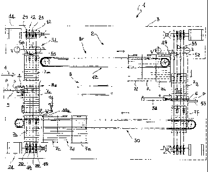
With reference to the figures mentioned; the reference 1 indicates as a,
whole a device for the accumulation and release of products P disposed in
ranks, produced according to the present invention. The device is of the type
comprising a storage unit 2 supported, by a fixed structure, not shown in the
2o drawings, and the body or outer containment casing 3 of which is shown
diagrammatically by dashed lines in the views in Figures 1 and 3.
The storage unit 2 is provided with a receiving opening 4 through which
are introduced the products P distributed in incoming .ranks on a feed belt 5,
and with a delivery opening 6 for the release of the products P leaving the
2s storage unit 2.
The storage unit 1 further comprises a plurality of container elements 7
which are movably guided within the storage unit 2, between the openings 4
4
CA 02524923 2005-09-16
WO 2004/087543 PCT/IT2003/000188
and 6, along a path 8 closed in a ring and defined by four respective
rectilinear
branches designated by 8a, 8b, 8c and 8d. More particularly, the path 8 has a
rectangular configuration with the pairs of branches 8a, 8b and 8c, 8d
parallel
and opposed to one another. The branches 8a and 8b conveniently extend
s vertically, meaning by the term "vertical" the direction perpendicular to
the
bearing surface at the base of the storage unit 2, along which are
respectively
located the receiving opening 4 and the delivery opening 6. On the other
hand, the branches 8c, 8d extend in a "horizontal" direction, that is to say,
parallel to the bearing surface of the storage unit.
Each container element 7 has a plurality of support surfaces, all
indicated by 9, rising one above the other and spaced from one ,another at a
regular pitch and capable of receiving one or more incoming ranks of products
from the belt 5. Said container elements 7 are conducted in sequence along
the path 8 (in a clockwise direction looking at Figure 1) to bring each
container
is 7 to be filled to the opening 4, in order to load onto the surfaces 9 the
ranks of
products P fed by the belt 5, and also to conduct the previously filled
containers 7 to the delivery opening 6 for the release of he products P
leaving
the storage unit.
On the path 8, the branch 8a is the ascending branch for loading of the
2o containers 7, while the branch 8b is the descending branch for unloading
the
containers. The branch 8c is the branch for storing the containers 7, along
which the latter are held in position one against the other, as will appear
clearly hereinafter. The branch 8d is the branch for transferring the
containers
7, already unloaded along the branch 8b, and for storing them while waiting to
2s be loaded again along the ascending branch 8a.
Along the branches of the path 8 means are also provided for actuating
the containers 7. It should be noted that the actuating means active along
5
CA 02524923 2005-09-16
WO 2004/087543 PCT/IT2003/000188
the branches 8a and 8b are structurally and functionally similar to one
another
and the description will therefore be limited to the ascending branch 8a, it
being intended that corresponding actuating means are provided for the
descending branch 8b and, where appropriate, details common to the two
s aforesaid branches being designated by the same numerical references.
Equally, actuating means structurally and functionally similar to one another
are provided along the storage branches 8c and 8d, and therefore the
description will be limited with reference only to the storage branch 8c,
details
common to these two branches of the path being designated, where
appropriate, by the same numerical references.
The actuating means arranged for the movement of the containers 7
along the ,branch 8a comprise first and second separate control means 10, 11,
respectively associated in sequence with one or another container 7, disposed
in succession to one another, of each pair of containers that can be observed
15 in the storage unit 2. In other words, containers 7 consecutive to one
another
along the path, which engage the branch 8a, are actuated in sequence,.
respectively by the actuating means 10 and 11, such that both of said
containers 7 are conducted from and towards the receiving opening 4 with
independent movements with respect to one another. The first control means
20 10 comprise two pairs of motor-driven chains 11a, 11b and 11c, 11d, wound
on respective drive 12 and return 13 sprockets and also.extending with their
operative branches parallel to the ascending branch 8a. The reference 14
indicates a servomotor capable of driving in synchronization the drive
sprockets of the chains 11a, 11b and, by means of a return 15, the drive
2s sprockets of the opposed pair of chains 11c, 11d. Each pair of chains is
further provided with respective coupling means, indicated as a whole by 16,
capable of engaging respective complementary coupling means 17 provided on
6
CA 02524923 2005-09-16
WO 2004/087543 PCT/IT2003/000188
the opposed sides of the containers 7 for raising same along the ascending
branch 8a of the storage unit 2. Said coupling means 16 comprise respective
plate-like members 18, secured, at a regular pitch, to each pair of chains
11a,
11b and 11c, 11d, from which there are raised in the same direction and
transversely, support rollers 19 capable of interfering with portions of
respective wings 20 protruding from the opposed sides of the containers, as
shown in figures 5 and 8.
The actuating means 11 in their turn comprise two pairs of motor-driven
chains 21a, 21b and 21c, 21d wound on respective drive 22 and return 23
1o sprockets and also extending with their operative branches parallel to the
ascending branch 8a. The reference 24 indicates a servomotor capable of
controlling in synchronization the drive sprockets of the chains 21a, 21b and,
by way of a return 25, the drive sprockets of the opposed pair of chains 21c,
21d. Each of said pairs of chains is further provided, with respective
coupling
is means, indicated as a whole by 26, structurally identical to the coupling
means
16, which are capable of engaging the complementary coupling means 17
provided on the opposed sides of the containers 7 for raising same, along the
ascending branch 8a. The coupling means 26 are secured to the chains 21a
21d at a regular pitch, conveniently equal to that provided for the coupling
2o means 16.
It will be noted, with particular reference to Figure 5, that on the one
hand the chains 11a, 11b, 21a, 21b and, on the other hand the chains 11c,
11d, 21c, 21d have return axes coaxial with one another with the operative
branches of each of the pairs of chains parallel and mutually spaced.
2s The actuating means provided along the descending branch 8b comprise
first and second separate control means, these also, for the sake of
simplicity,
indicated by 10, 11, in their turn including respectively two pairs of chains
31a,
7
CA 02524923 2005-09-16
WO 2004/087543 PCT/IT2003/000188
31b, 31c, 31d and 41a, 41b, 41c, 41d, having the same structure as the
chains associated with the ascending branch 8a, to the description of which
reference should be made for any further detail. In this case also, containers
7 consecutive to one another, which engage the branch 8b, are moved from
and towards the delivery opening 6 with independent movements with respect
to one another. For the movement of the containers along the storage branch
8c, first conveying means are provided, indicated 'as a whole by 42, and
capable of conducting the containers 7 (filled with products P) one after the
other in a collected position and one against the other. Said means 42
1o comprise pairs of motor-driven chains 43 wound on respective drive 44 and
return 45 sprockets, and having their operative branches elongated
horizontally along the branch 8c. More particularly, pairs of double motor-
driven chains are provided, bearing idle rollers 46 pivoted on pins 47
constituting pins of two single chains side by side and firmly secured to each
is other (Figure 7). The rollers 46 are mounted so as to be idle, and support
the
wings 20 of the containers 7, at a groove 48 provided 'at the bottom on the
wings themselves. The chains 43 in their turn are supported and slidably
guided on guide profiles 48a extending parallel to the branch 8c and connected
to the fixed structure of the storage unit 2. In the movement of the chains
43,
2o each container 7 is moved jointly with the latter along the branch 8c,
owing to
the friction developed in the bearing contact of the wings 20 on the
respective
idle rollers 46. Arresting means, indicated by 49, are provided at the arrival
end of the branch 8c and are capable of interfering with the container 7 to
retain it (together with the remaining containers pushed against it) in one
2s direction in the end position reached, independently of the movement of the
chains, owing to the creep and/or relative rolling between the idle rollers
and
the wings of the containers. The accumulation of the containers 7 and their
8
CA 02524923 2005-09-16
WO 2004/087543 PCT/IT2003/000188
retention is therefore ensured by the arresting means 49 during the
continuous movement of the chains 43.
For the movement of the containers 7 along the lower transfer branch
8d, second conveying means are provided, indicated as a whole by 50, having
s a structure substantially identical to the conveying means 42. These also
include pairs of double motor-driven chains 43 with idle support rollers 46
for
supporting the containers 7, for details of which reference should be made to
the description provided previously with reference to the branch 8c, co-
operating with arresting means 49a in a manner entirely similar to those
io provided in the branch 8c. .
The reference 51 designates thrust means arranged for transferring
each of the containers 7, in the passage along the path 8, from the ascending
branch 8a to the storage branch 8c and from the latter to the descending
branch 8b. Said thrust means 51 are produced for example by means of one
15 or more thrust members 52 firmly secured to the movement of a chain 53 and
capable of interfering with the container 7 to move same from one branch to
the other at the confluence of said branches along the path 8.
The reference 54 indicates a thrust member capable of displacing the
ranks of products P from each support surface 9 to an outlet belt 55, in the
2o phase of unloading of the containers 7 and release of the products leaving
the
storage unit 2.
For greater understanding of the operation of the device described
hereinafter, the container members illustrated in Figures 1 and 3 are
designated individually by the numerical references 7a, 7b, 7c, 7d, 7e, 7f,
7g,
2s 7h, 7i, 71 and 7m, so as to facilitate detection of the position thereof
within the
storage unit.
9
CA 02524923 2005-09-16
WO 2004/087543 PCT/IT2003/000188
In an initial reference phase of operation, illustrated in Figure 1, the
container 7a is positioned at the receiving opening 4, with the belt 5 in
alignment with the top support surface 9 of the container 7a for the transfer
of
a rank of products P onto said surface. The container 7a is raised by the
s control means 10, by means of coupling with the chains 11a - 11d. A sensor
57 is provided to detect the passage of the rank and to operate the
servomotor 14 in order to displace the container 7a by a pitch (equal to the
distance between consecutive surfaces 9) so as to complete the loading of all
the support surfaces 9 with respective ranks of products P.
io In this phase the container 7b is uncoupled from the storage branch 8d
and is positioned below the container 7a. The containers 7c,.7d, 7e are.
retained in a position one against the other on the branch 8c by the arresting
means 49a. The container 7m, after filling has taken place, is raised until it
is
aligned with the conveyor chain 43 for its transfer along the branch 8c by the
1s thrust means 50. The full containers 71, 7i, 7h are stored on the branch
8c,
retained by the arresting means 49. The container 7g is displaced ~by the
chains 31a-31d (by means of mutual engagement of the respective coupling
and complementary coupling means 16, 17) by an intermittent movement to
the delivery opening 6 along the descending branch 8b to allow the unloading
20 of the ranks of products P from the respective support surfaces 9. The
container 7f is coupled to the chains 41a-41d after the unloading of the
products onto the belt 55 has taken place and is displaced in a continuous
motion in the direction of the storage branch 8d for empty containers.
In a following phase of operation of the device 1, illustrated in figure 3,
2s the container 7a, raised by the control means 10, is at the end of the
filling
phase with the last support surface 9 (that at the bottom level) aligned with
the belt 5 for loading into the container 7a the last rank of products P. In
this
CA 02524923 2005-09-16
WO 2004/087543 PCT/IT2003/000188
phase the container 7b is moved closer to the container 7a by means of the
respective separate control means 11 until it reaches .a position in which the
distance between the last surface 9 of the,container 7a and the top surface of
the container 7b is equal to the pitch existing between consecutive surfaces 9
s of the containers. In this way the ranks of products can be introduced into
the
containers at an always constant pitch at a uniform rhythm also during the
passage from one container to the next. Figure 4 shows the lined up state of
the containers 7a, 7b.
In this phase, in addition, the containers 7c, 7d, 7e are held stored on
to the branch 8d by actuation of the arresting means 49a. The container 7f,
previously emptied, is in transit along the branch 8d until it 'reaches the
position pushed against the container 7e. The container 7m, transferred onto
the branch 8c, is moved along this storage branch. The container 7h is
transferred by the thrust means 51 onto the descending branch 8b and is
is controlled by the chains 41a-41d while approaching the container 7g. Owing
to the control movements, independent of one another, of the containers 7g
and 7h, the distance between the top surface 9 of the container 7g and the
last lower surface of the container 7h may be made equal to the pitch existing
between the surfaces 9 of the same container, so as to ensure release of the
2o ranks of products at a constant pitch in a uniform rhythm also during the
passage from one container to the next.
The phases illustrated in Figures 1 and 3 are then repeated cyclically in
order to obtain in sequence the loading of each container along the ascending
branch 8a and the emptying of corresponding containers along the descending
25 branch 8d.
It is understood that the number of containers provided in the storage
device may vary according to specific requirements. It should be noted that
11
CA 02524923 2005-09-16
WO 2004/087543 PCT/IT2003/000188
the storage capacity is substantially linked to the number and to the
dimensions of the containers that can be pushed one against one the other
along the storage branch 8c, and the storage volume can therefore be
increased for example by elongating the storage unit horizontally and/or
s increasing the number of support surfaces of each container. The ascending
and descending branches of the storage device, which define the overall
vertical dimension thereof, serve substantially to ensure the filling and
emptying of at least a pair of containers consecutive to each other, by means
of movements independent of one another. In this way the phases of filling
Io and emptying of the containers are rendered substantially independent of
the
movement of the remainder of the containers within the storage unit.
The invention thus solves the problem posed while providing numerous
advantages with respect to the known solutions.
A principal advantage lies in the fact that in the device according to the
is invention it is possible to maintain, both in the filling phase and in the
emptying phase, a distance between the last support surface of one container
and the first surface of the container adjacent thereto which is equal to the
pitch of the support surfaces. This equality of pitches permits movement of
the containers at constant speed in the loading/unloading phases without
2o inducing acceleration/deceleration of the containers themselves,
responsible
for any unwanted swaying motions.
Another advantage is due to the fact that in the ascending and
descending branches the containers are controlled individually with
movements independent of one another. Since the full container can in fact
2s be moved away at a speed different from that consecutive thereto in the
filling
phase, the efficiency and productivity of the device are increased.
12
CA 02524923 2005-09-16
WO 2004/087543 PCT/IT2003/000188
Another advantage is that the container is not bound, as in the known
systems, to a fixed chain pitch, which pitch constrains the entire movement of
the series of containers. According to the invention, the container filled on
the
ascending branch at a certain displacement speed, may directly follow the path
s towards the storage and emptying side at a different (and higher) speed and
at a pitch different from the container which precedes it. This advantage is
also reflected in the phase of emptying of the containers.
Yet another advantage is that the movement necessary for passing from
one container to the next during filling, in contrast to the known systems,
does
1o not limit the running speed. In the known solutions, in fact, the entire
series
of containers is moved along the path defined in the storage unit with a need
for considerable power for moving the entire train of containers. According to
the invention, the branches for filling and emptying of the containers are
actuated independently of the branches for storage of the containers, with
15 consequently less power required and the possibility of using different
displacement speeds in order to optimize the storage and release times for
products in the storage unit.
Moreover, in the device of the invention, the provision of rectilinear
branches in the loading/unloading and torage paths makes it possible to
2o eliminate unwanted oscillating and swaying movements of the containers
which, on the other hand, are generated in the knowri systems, especially in
the presence of returns and bends in the paths described within the storage
units.
Another advantage is that the containers of the device according to the
2s invention are not rigidly secured to the conveyor chains, with consequent
ease
of replacement and/or removal for maintenance operations (for example in the
washing operations).
13
CA 02524923 2005-09-16
WO 2004/087543 PCT/IT2003/000188
Yet another advantage is that the device according to the invention
makes it possible to obtain a reduced travel for each container from the
filling
point to the emptying point, without the need for a complete revolution of
travel of the chain, as provided in the known systems.
14