Note: Descriptions are shown in the official language in which they were submitted.
CA 02524925 2005-11-07
WO 2004/099650 PCT/CA2004/000667
LINEAR TENSIONER
Field of the Invention
The invention relates to. a linear tensioner for tensioning a serpentine belt
of an
automobile engine. More particularly, the invention relates to a mechanical
linear
tensioner.
Description of the Related Art
Linear tensioners are commonly used to continuously tension a serpentine belt
of
an automobile engine. Typically, a linear tensioner includes a hydraulic or
pneumatic
cylinder. Conventional linear tensioners are utilized when there is
insufficient space on
an engine for a rotary tensioner.
Linear tensioner assemblies typically comprise a carrier plate pivotally
mounted to
the engine of the vehicle for carrier a tensioner pulley. The serpentine belt
is wound
around the tensioner pulley. The linear tensioner is coupled between the
carrier plate
opposite the tensioner pulley and the engine to provide constant tension on
the serpentine
belt.
Hydraulic or pneumatic tensioners suffer from a phenomenon know as "pump
up". The tensioner will build up pressure in response to the vibrations of the
belt and will
not release this pressure. The tensioner has a tendency to over-tensioner the
belt and thus
reduce the lifespan of the belt.
Other mechanical linear tensioners are shown in the prior art. Such tensioners
are
shown in United States Patent nos. 6,422,964. However, such tensioners require
a pin to
hold the tensioner together during shipping and must be removed after the belt
has been
applied over the pulley.
Summary of the Invention
It is desirable to provide a linear tensioner that does not over-tension the
serpentine belt.
It is desirable to provide a linear tensioner comprising a first sleeve and a
second
sleeve slidably received within one another to house a biasing spring that
urges the
sleeves apart. The first sleeve and the second sleeve have a connection
therebetween that
limits the sliding movement against the bias of the biasing member, retaining
the first
sleeve within the second sleeve.
1
CA 02524925 2005-11-07
WO 2004/099650 PCT/CA2004/000667
According to one aspect of the invention, a linear tensioner has a
longitudinally
extending first sleeve having an end configured for pivotal coupling and a
longitudinally
extending second sleeve having an end configured for pivotal coupling. The
second
sleeve slidably receives the first sleeve and frictionally engages therewith.
A biasing
member extends between the sleeves and urges the sleeves apart. The ftrst
sleeve
operatively engages with the second sleeve enabling sliding movement within a
range and
retains the sleeves together against the bias of the biasing member.
According to another aspect of the invention, the linear tensioner has sleeves
that
are coupled together in a bayonet fashion.
Brief Description of the Drawings
Advantages of the present invention will be readily appreciated as the same
becomes better understood by reference to the following detailed description
when
considered in connection with the accompanying drawings, wherein:
. Figure 1 is a front view of, an automobile engine incorporating a linear
tensioner
according to one embodiment of the invention;
Figure 2 is a partially exploded perspective view of the linear tensioner;
Figure 3 is a cross sectional view of the linear tensioner;
Figure 4 is an exploded side view of a second embodiment of the linear
tensioner;
~ Figure 5 is a cross sectional view of the second embodiment of the linear
tensioner;
Figure 6 is a perspective view of a third embodiment of the linear tensioner;
Figure 7 is a cross sectional view of the third embodiment of the linear
tensioner;
Figure ~ is a perspective view of a fourth embodiment of the linear tensioner;
Figure 9 is a cross sectional view of the fourth embodiment of the linear
tensioner;
Figure 10 is a perspective view of a fifth embodiment of the linear tensioner;
Figure 11 is a cross sectional view of the fifth embodiment of the linear
tensioner;
Figure 12 is a perspective view of a sixth embodiment of the linear tensioner;
Figure 13 is a cross sectional view of the sixth embodiment of the linear
tensioner;
Figure 14 is a perspective view of a seventh embodiment of the linear
tensioner;
Figure 15 is a cross sectional view of the seventh embodiment of the linear
tensioner;
2
CA 02524925 2005-11-07
WO 2004/099650 PCT/CA2004/000667
Figure 16 is a cross sectional view of an eighth embodiment of the linear
tensioner;
Figure 17 is a partially exploded perspective view of a ninth embodiment of
the
linear tensioner;
Figure 18 is a perspective view of the ninth embodiment of the linear
tensioner;
Figure 19 is a cross sectional view of the ninth embodiment of the linear
tensioner;
Figure 20 is another cross sectional view of the ninth embodiment of the
linear
tensioner;
Figure 21 is a perspective view of a tenth embodiment of the linear tensioner;
Figure 22 is a cross sectional view of a tenth embodiment of the linear
tensioner;
and
Figure 23 is another cross sectional view of a tenth embodiment of the linear
tensioner. '
Detailed Description of the Preferred Embodiments
Referring to Figure l, an engine for an automotive vehicle is generally
indicated at
10. A crank sleeve 12 is rotatably driven by torque provided by the engine 10.
A crank
pulley 14 is fixedly secured to the crank sleeve 12. The engine 10 also
includes a
plurality of engine driven accessories, such as an alternator or water pump.
Each of the
engine driven accessories includes a rotatable input sleeve 16 and an input
pulley 18
fixedly secured thereto. Each of the engine driven accessories is driven by
the rotation of
the input sleeve 16. A serpentine belt 20 is wrapped around the crank pulley
14 and the
input pulleys 18. °The belt 20 delivers the torque provided by the
engine 10 from the
crank pulley 14 to the input pulleys 18. The belt 20 converts rotational
movement of the
crank pulley 14 into rotational movement of the input pulleys 18. Described in
detail
below, a tensioner assembly 30 keeps the belt 20 in tension to prevent
slippage of the belt
20 relative to the crank 14 and input 18 pulleys.
The tensioner assembly 30 includes a Garner plate 32. A rirst pivot assembly
34
pivotally interconnects the carrier plate 32 to the engine 10. The first pivot
assembly 34
includes a collar forming an aperture through the carrier plate 32 for
supporting a bushing
and plurality of dampening washers. A mounting bolt is inserted through each
of the
3
CA 02524925 2005-11-07
WO 2004/099650 PCT/CA2004/000667
bushing, washers and aperture to pivotally secure~the tensioner assembly 30 to
the engine
and the washers provide dampening to quell vibratory oscillations occurring in
the belt
20. The pivot assembly 34 is more fully described in Applicant's German patent
no.
10053186.
5 A tensioner pulley 36 is rotatably coupled to the carrier plate 32 by a
second pin
38 spaced opposite the first pivot assembly 34. The belt 20 is wrapped around
the
terisioner pulley 36. The tensioner pulley 36 pivots with the plate 32 about
the first pivot
assembly 34. When the carrier plate 32 pivots in the counterclockwise
direction, as
viewed in Figure l, the tensioner pulley 36 presses into the belt 20 to
increase the tension
10 of the belt 20. When the carrier plate 32 pivots in the clockwise
direction, the tensioner
pulley 36 moves away from the belt 20 to decrease tension in the belt 20.
Linear tensioners disclosed as various embodiments of the present invention
include friction strut or sleeve designs capable of providing symmetrically
damped,
asymmetrically damped, and/or un-damped forces. Symmetric damping is generated
by
the sliding interface between the sleeve and sleeve of the linear tensioner
and is
independent of the direction of movement of the components. Asymmetric damping
is
achieved, again by the frictional interface of the sleeve and sleeve, but the
damping forces
are dependant on the direction of movement of the components. Generally the
damping
forces are greater for compressive movements than for extensions of the
sleeve. LTn-
damped linear tensioners of the present invention have a minimal frictional
engagement
between the sleeve and sleeve. The sleeve and sleeve function to guide the
compression
of a spring disposed within the sleeve and sleeve. Typically, a damping pack
or
accessory may be included in un-damped embodiments and can be located at the
pivot
where the linear tensioner attaches to an engine, as discussed above with
respect to the
first pivot assembly 34, and will be discussed in more detail below.
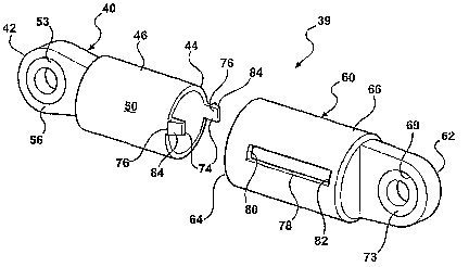
Referring to Figures 2 and 3, a linear tensioner is generally indicated at 39.
The
linear tensioner 39 includes a first sleeve 40 that extends between a proximal
end 42 and a
distal end 44. The sleeve 40 is preferably cast or machined aluminum. The
sleeve 40
includes a tubular body 46 that extends between the proximal 42 and distal 44
ends. The
body 46 includes generally cylindrical inner 48 and outer 50 surfaces. The
inner surface
48 extends between a first or inner abutment surface 52 and the distal end 44.
A pivot
aperture or eye 53 is formed at the proximal end 42 for seating a first
bushing 56 therein.
4
CA 02524925 2005-11-07
WO 2004/099650 PCT/CA2004/000667
The bushing is preferably a pushed in or press fit metal DLT type of bushing.
However, a sliding fit foil type of bushing, a spray on or dipped type of
bushing, or a
rubber eyelet type of bushing may be used.
A third pin 54 extends through the bushing 56 and pivotally interconnects the
proximal end 42 of the sleeve 40 to the engine 10. Alternatively, the proximal
end 42 of
the sleeve 40 may be attached to the engine 10 by any suitable fastener, such
as, a bolt,
snap fit connection, ball and socket connection, or the like, as are commonly
known
connector to one of ordinary skill in the art.
The linear tensioner 39 also includes a second sleeve 60 extending between a
proximal end 62 and a distal end 64. The second sleeve 60 is preferably molded
plastic.
The sleeve 60 includes a generally cylindrical body 66 that extends between
the proximal
62 and distal 64 ends. The sleeve body 66 includes a generally cylindrical
inner surface
68 that extends between a second inner abutment surface 70 and the distal end
64 of the
sleeve 60. A pivot aperture or eye 69 is formed in the sleeve body 66 adjacent
the
proximal end 62 for seating a second bushing 73 therein.
A fourth pin 71 extends through the bushing 73 and pivotally interconnects the
proximal end 62 of the sleeve to the plate 32.
The outer surface 50 of the body 46, is slidably received within the inner
surface
68 of the sleeve 60. The outer surface 50 of the body 46 and the inner surface
68 of the
sleeve 60. are sized to create a predetermined amount of friction. The
friction dampens
the movement of the sleeve 60 relative to the sleeve 40 in a generally
symmetrical
manner, wherein the amount of dampening is consistent during both compression
and
extension of the linear tensioner 39.
A biasing member 72, preferably a helical coil spring, is housed within the
sleeves
40 and 60 and continuously compressed between first 52 and second 70 abutment
.
surfaces, such that the sleeve 40 and the sleeve 60 are axially biased apart.
The axial bias
of the sleeve 60 relative to the sleeve 40 rotatably biases the plate 32 in
the
counterclockwise direction, which, in turn, tensions the belt 20.
The sleeves 40 and 60 have an interconnection that enables sliding movement
therebetween and holds the two sleeves together against the bias of the
biasing member
72. The interconnection generally comprises a projection slidably engaging a
slot. The
slot defines a range of sliding movement, with one end defining a limit. The
range of
5
CA 02524925 2005-11-07
WO 2004/099650 PCT/CA2004/000667
sliding movement includes a working or operation range of movement. The slots
78 have
a length that defines the range of sliding movement that is greater than the
expected
working range of the tensioner 39.
In the first preferred embodiment, the interconnection is a pair of
projections or
flexible fingers 74 formed along diametrically opposed sides of the body 46 of
sleeve 40.
The tip of the flexible forgers 74 is defined by a tang 76. A ramped surface
84 is formed
in each tang 76 to facilitate ingress of the body 46 into the sleeve body 66,
while
preventing egress.
The sleeve 60 includes a corresponding pair of elongated slots 78 extending
between first 80 and second 82 ends formed in the sleeve body 66 that
correspond to the
tangs 76. Each of the tangs 76 projects through the corresponding slot 78 and
is slidably
engaged therein. The tangs 76 limit the travel of the sleeve 60 away from
sleeve 40.
During insertion of the body 46 into the sleeve body 66,, the ramped surface
84
engages the distal end 64 of the sleeve 60. The engagement of the ramped
surface 84
with the distal end 64 of the sleeve 60 elastically deforms the fingers 74 and
inwardly
displaces the tang 76 until the tang 76 slidably engages the slot 78. The
sliding
movement of the tangs 76 within the slots 78 is constrained by the first 80
and second 82
ends of the slots 78, which defines the range of axial movement of the sleeve
60 relative
to the sleeve 40. The locking connection between the tangs 76 and slots 78
slidably
couple the sleeve 40 to the sleeve 60, with the spring 72 compressed
therebetween so that
the tensioner assembly 30 may be assembled, stored, shipped and/or assembled
to the
vehicle engine as a pre-assembled component.
An un-damped version of the first embodiment can be utilized by minimizing the
frictional engagement of the sleeve 40 with the sleeve 60, .with the other
components
remaining unchanged.
The first embodiment of the linear tensioner 39 may be utilized in a front end
accessory drive system that includes an overrunning decoupler 19, as best seen
in Figure
1. The overrunning decoupler 19 is typically associated with an alternator,
due to its
large effect on the tension within the belt 20 because of its high inertia.
The overrunning
decoupler 19 reduces the dynamic tensions within the belt 20 providing an
overall system
requiring lower damping forces.
6
CA 02524925 2005-11-07
WO 2004/099650 PCT/CA2004/000667
An overrunning decoupler in its simplest form includes a belt engaging member
operatively connected to a hub structure by a resilient member and a one way
clutch
connected to each other. The one way clutch and resilient member preferably
comprise a
helical spring assembly. Acceleration and rotation of the pulley in the driven
direction
relative to the hub creates friction between the inner peripheral surface of
the pulley and
preferably all of the coils of the clutch spring. The clutch spring is
helically coiled such
that the friction between the inner peripheral surface of the pulley and at
least one of the
coils would cause the clutch spring to expand radially outwardly toward and
grip the
inner peripheral surface. Continued rotation of the pulley in the driven
direction relative
to the hub would cause a generally exponential increase in the outwardly
radial force
applied by the coils against the inner peripheral surface until all of the
coils of the clutch
spring become fully brakingly engaged with the pulley. When the pulley
decelerates, the
hub driven by the inertia associated with the rotating drive sleeve and the
rotating mass
within the alternator will initially "overrun" or continue to rotate in the
driven direction at
a higher speed than the pulley. More specifically, the higher rotational speed
of the hub
relative to the pulley causes the clutch spring to contract radially relative
to the inner
peripheral surface. The braking engagement between the clutch spring and the
pulley is
relieved, thereby allowing overrunning of the hub and drive sleeve from the
alternator
relative to the pulley. A preferred decoupler design is described in
Applicant's IJ.S.
Patent No. 6,083,130 and is commonly assigned to the assignee of the present
invention.
All of the embodiments of the linear tensioner described above and below can
be utilized
in a front end accessory drive system including an overrunning decoupler 19.
Referring to Figures 4 and 5, a second embodiment of the linear tensioner 39
is
shown. The sleeve 40 and sleeve 60 of the linear tensioner 39 of the second
embodiment
are slidably coupled by a bayonet-type locking connection therebetween.
Specifically,
the linear tensioner 39 similarly includes a sleeve 40 extending between
proximal 42 and
distal 44 ends. A cylindrical body 46 is defined by inner 48 and outer 50
surfaces. The
inner surface 48 extends between a first abutment surface 52 and the distal
end 44. An
aperture 53 extends through the proximal end 42 for attaching the sleeve 40 to
the carrier
plate 32. A hub 21 projects axially from the first abutment surface 52 for
seating one end
of a biasing member 72 within the body 46. An offset locking slot 22 is
recessed into the
outer surface 50 of the body 46 and extends axially from the distal end 44
toward the
7
CA 02524925 2005-11-07
WO 2004/099650 PCT/CA2004/000667
proximal end 46. The offset locking slot 22 includes a first linear portion 23
and a
generally parallel second linear portion 24 offset radially from the first
linear portion 23.
The first and second linear portions 23, 24 are interconnected by a third
portion 25
extending circumferentially and generally perpendicularly therebetween. The
first linear
portion 23 has a flared entry 26 adjacent the distal end 44 of the body 46.
The linear tensioner 39 of the second embodiment of Figures 4 and 5 further
includes a sleeve 60 extending between proximal 62 and distal 64 ends. A
cylindrical .
sleeve body 66 includes an inner surface 60 that extends between a second
abutment
surface 70 and the distal end of the sleeve 60. An aperture 69 extends through
the
proximal end 62 for attaching the sleeve 60 to the engine 10. A hub 27
projects axially
from the second abutment surface 70 for seating the opposite end of a biasing
member 72
within the sleeve body 66. A pair of guide tabs 28 projects radially inwardly
from
opposing sides of the inner surface 68 of the sleeve body 66 adjacent the
distal end 64
thereof. A pair of openings 29 extend through the inner surface 68 along
opposite sides
of the sleeve body 66 adjacent the proximal end 62 thereof for allowing air to
escape from
within the body 46.
In assembly, the sleeve 40 and sleeve 60 are slidably and rotatably connected
by
the bayonet locking connection. The biasing member 72 is positioned between
the sleeve
40 and sleeve 60 and aligned for opposing ends thereof to be seated about the
hubs 21,
27, respectively, and compressed therebetween. The guide tabs 28 are axially
and
radially aligned with the flared entry 26 of the first linear portion 23 of
each respective
offset locking slot 22. The sleeve 40 and sleeve 60 compress the biasing
member 72
axially therebetween as the tabs 28 slide axially along the first linear
grooves 23 and into
the third groove 25. The sleeve 40 is then rotated relative to the sleeve 60
to translate the
tabs 28 along the third portion 25 into the second linear portion 24. After
rotation, the
compressed 'biasing member 72 maintains the tabs 28 between first and second
end walls
31, 33 of the second linear portion 24, thus coupling the sleeve 40 and sleeve
60, and
defining the range of longitudinal movement of the sleeve 60 relative to the
sleeve 40.
Any air that may be trapped and compressed between the sleeve 40 and sleeve 60
may
escape through the openings 29 in the sleeve 60.
Referring to Figures 6 and 7, a third embodiment of the linear tensioner 139
is
shown, wherein elements of the alternative embodiment similar to those in the
first and
8
CA 02524925 2005-11-07
WO 2004/099650 PCT/CA2004/000667
second embodiments are indicated by reference characters that are offset by
100. At least
one, but preferably a plurality of longitudinally extending slots or grooves
86 is integrally
formed in the outer surface 150 of the sleeve 140. The inner surface 168 of
the sleeve
160 has a series of corresponding pads 87. The pads 87 slide within the
grooves 86. The
end of groove 86 limits the extent to which the sleeves 140 and 160 may travel
away from
each other. The raised pads 87 provide for the control of thermal expansion
while further
providing a discharge path therebetween for contaminants that have entered the
linear
tensioner 139.
Referring to Figures 8 and 9, a fourth embodiment of the linear tensioner is
generally indicated at 239. A retaining ring 88 is fixedly secured to the
distal end 264 of
the sleeve 260. At least one spring washer 89 is supported between the
retaining ring 88
and the sleeve 260 for fractionally engaging the outer surface 250 or pads 286
of the
sleeve 240. The friction between the spring washer 89 and the outer surface
250 or pads
286 dampens the sliding movement of the sleeve 260 relative to the sleeve 240.
Preferably, the spring washer 89 is conical to provide asymmetrical or
isometric
dampening, wherein the friction is greater, for example, during compression of
the linear
tensioner 239 than during extension.
Refernng to Figures 10 and 11, a fifth embodiment of the linear tensioner is
generally indicated at 339. A sleeve 90 is coupled between the outer surface
350 of the
sleeve 340 'and the inner surface 368 of the sleeve 360. The sleeve 90
includes at least
one, but preferably a plurality of fingers 91. Each of the plurality of
fingers 91 extends
outwardly at an angle relative to the axis of the sleeve 340, such that each
of the plurality
of fingers 91 fractionally engages the inner surface 368 of the sleeve 360
during
compression of the linear tensioner 339. The frictional engagement of the
plurality of
fingers 91 with the inner surface 368 of the sleeve 360 tends to deflect or
bend the
plurality of fingers 91 until each are generally normal to the axis of the
sleeve 340. The
deflection of the plurality of fingers 91 pushes the sleeve 90 radially
inwardly relative to
the outer surface 350 or pads 386 of the sleeve 340, which increases the
frictional force
and dampens the movement of the sleeve 360 relative to the sleeve 340.
Refernng to Figures 12 and 13, a sixth embodiment of the linear tensioner is
generally indicated at 439. The linear tensioner 439 includes a retaining
sleeve 92 that is
fixedly secured to the distal end 464 of the sleeve 460. At least one sprag 93
is coupled
9
CA 02524925 2005-11-07
WO 2004/099650 PCT/CA2004/000667
between the retaining sleeve 92 and the outer surface 350 of the sleeve 340.
The sprag 93
includes a spring tab 94 that pivotally biases the sprag 93 about a fulcrum
point 94a. The
spring tab 94 pushes the sprag 93 away from the retaining sleeve 92 and into
frictional
engagement with the outer surface 350 of the sleeve 340: The frictional
engagement
between the sprag 93 and the outer surface 350 or pads 386 of the sleeve 340
dampens the
compression and the extension of the linear tensioner 439. The frictional
engagement
between the sprag 93 and the outer surface 350 or pads 386 is greater during
compression
of the linear tensioner 439 than during extension due to the pivotal bias of
the sprag 93
about the fulcrum point 94a.
Referring to Figures 14 and 15, a seventh embodiment of the linear tensioner
is
generally indicated at 539. A sprag ring 95 is fixedly secured to the distal
end, 544 of the
sleeve 540. At least one, but preferably a plurality of spaced apart sprag
members 96 is
integrally formed on the sprag ring 95. During assembly of the sleeve 540 and
the sleeve
560, the plurality of sprag members 96 are displaced inwardly relative to the
inner surface
568 of the sleeve 560. The inward displacement of the sprag members 96
torsionally
preloads the sprag ring 95, such that the plurality of sprag members 96 are
continuously
biased into frictional engagement with the inner surface 568 of the sleeve
560. The
frictional engagement of the plurality of sprag members 96 and the inner
surface 568 of
the sleeve 560 dampens the compression of the linear tensioner 539.
Referring to Figure 16, an eighth embodiment of the linear tensioner is
generally
indicated at 639. A plurality of sprag members 97 is integrally formed at the
distal end
644 of the sleeve 640 and pivotally secured thereto by a living hinge
connection at 97a
created by a notch 97b cut in the sleeve 640. Each of the plurality of sprag
members 97
includes a step surface 98. A second biasing member 99, preferably in the form
of a
helical coil spring, is compressed between the step surfaces 98 and the second
abutment
surface 670 of the sleeve 660. The second biasing member 99 biases the
plurality of
sprag members 97 toward frictional engagement with the inner surface 668 of
the sleeve
660. The frictional engagement between the plurality of sprag members 97 and
the inner
surface 668 of the sleeve 660 dampens the compression and extension of the
linear
tensioner 639.
Refernng to Figures 17-23, there will be described un-damped embodiments of
the linear tensioner of the present invention.
CA 02524925 2005-11-07
WO 2004/099650 PCT/CA2004/000667
Referring to Figures 17-20, there is shown a ninth embodiment of the linear
tensioner 739 of the present invention. As this embodiment is un-damped; the
sleeve 740
and sleeve 760 have iniiiimal frictional engagement. As with the previously
described
embodiments, a biasing member or spring (not shown) is continuously compressed
between first 752 and second 770 abutment surfaces, such that the sleeve 740
and sleeve
760 are axially biased apart.
The ninth embodiment includes an alternative attachment for coupling the
sleeve
740 with the sleeve 760. The sleeve 740 includes a bayonet projection 701
extending
radially from the sleeve 740. The bayonet projection 701 is received in a
keyed slot 702
formed in an end cap 704 on the distal end of the sleeve 760. The bayonet
projection 701
on the sleeve 740 is aligned with the keyed slot 702, as shown in Figure 17
and then
moved longitudinally within the sleeve 760 and turned radially to abut an
engaging
surface 703 defined by the inner surface of the end cap 704 of the sleeve 760,
as shown in
Figure 18. In this mariner the sleeve 740 is maintained within the sleeve 760.
It is to be
~ understood that any of the attachments described can be utilized by any of
the other
embodiments discussed in the application, including damped versions of the
linear
tensioner. The bayonet projection 701 described with the un-damped embodiment
is
done for the sake of clarity and avoiding repetitive descriptions for both the
damped and
un-damped versions of a linear tensioner.
Referring to Figures 21-23, there is shown a tenth embodiment of the linear
tensioner 839 of the present invention. As with the previous embodiment, the
tenth
embodiment is un-damped having the sleeve 840 and the sleeve 860 in minimal
frictional
engagement. As with the prior embodiments, a biasing member or spring (not
shown) is
continuously compressed between first 852 and second 870 abutment surfaces,
such that
the sleeve 840 and sleeve 860 are axially biased apart.
The alternative attachment of the tenth embodiment for coupling the sleeve 840
with the sleeve 860 comprises a slot 801 formed circumferentially through the
sleeve 860
in which a C-shaped snap ring 802 is introduced. The sleeve 840 is placed
within the
sleeve 860 and then the snap ring 802 is introduced into the slot 801 to
engage a surface
803 formed by a stepped down notched outer surface 804 in the sleeve 840 to
maintain it
within the sleeve 860. As with the above described embodiments, the snap ring
802
11
CA 02524925 2005-11-07
WO 2004/099650 PCT/CA2004/000667
version of attachment may be used by any of the previously described
embodiments,
including damped versions of the linear tensioner.
The damping characteristics of the tensioner assembly may varying and are
specific to the particular engine, accessory loads and engine torsionals. The
damping
may be provide by the washers of the first pivot assembly 34, friction between
the sleeve
40 and sleeve 60, damping losses within the spring 72 as it is compress and
extended
and/or friction due to the rotational movement between the pivot bushings 56,
73 and
mounting bolts, as well as, the above-described embodiments of the invention.
The invention has been described in an illustrative manner, and it is to be
understood that the terminology, which has been used, is intended to be in the
nature of
words of description rather than of limitation. Many modification and
variations of the
present invention are possible in light of the above teachings. It is,
therefore, to be
understood that within the scope of the appended claims, the invention may be
practiced
other than as specifically described.
12