Note: Descriptions are shown in the official language in which they were submitted.
CA 02525013 2005-11-07
WO 2004/102107 PCT/DE2004/000952
Rapid-Fire Weapon
The invention relates to a weapon, in particular a rapid-fire
weapon.
Such a rapid-fire weapon is e.g. known from US patent
6,138,395 or EP-A1-1069394. This weapon comprises a barrel
and a projectile that is insertable into the barrel and
comprises several sub-projectiles that are stacked one behind
the other in the longitudinal direction of the barrel and
supported on each other, a propellant charge being provided
behind each sub-projectile. As a rule, the sub-projectiles
are accommodated in a sleeve, the wall of the sleeve being
provided with electric igniters in the area of the individual
propellant charges. The igniters are successively
electrically ignited by means of an ignition means and, due
to this, the propellant charges are sequentially ignited so
that the sub-projectiles are successively ejected from the
barrel.
As a rule, the individual sub-projectiles have a caliber of
40 mm; the fire frequency ranges from 2 to 5 Hz.
Due to the simple stacking of the sub-projectiles in the
sleeve, the ejection forces cannot be reproduced in a defined
manner for the individual shots. Moreover, the electrical
igniters that are always present in the sleeve are
susceptible to corrosion and aging and are not safe against
CA 02525013 2005-11-07
2
electromagnetic interferences which, among other things is a
problem for transport and storage.
The invention is based on the object of modifying the known
rapid-fire weapon so that a reliable function of the rapid-
fire weapon is achieved, which is reproducible in the entire
sequence of the individual shots.
Moreover, it should also be possible to safely store the
weapon with all its parts, including the sub-projectiles, for
a long period of time and to safely transport it.
For this purpose, it is a first feature of the invention that
the sub-projectiles are firmly mechanically connected with
each other in the area of the propellant charges, a rated
break point being provided in this mechanical connection,
which, after igniting the respective propellant charge by its
propellant gases is broken in a defined fashion.
A second feature consists in that the propellant charges are
in each case ignited by means of pyrotechnical ignition
charges, namely by their ignition jet, i.e. by their
propellant gases. The ignition jet of an ignition charge
enters in each case a ignition duct which penetrates the wall
of the barrel and ends in the area of a propellant charge for
a specific sub-projectile.
Due to the firm connection of the sub-projectiles by means of
a defined rated break point it is achieved that the sub-
projectiles are only ejected from the barrel if a very
specific pressure of the propellant gases has been developed.
Thus, the ejection conditions are identical for each shot so
CA 02525013 2005-11-07
3
that the sub-projectiles have the same discharge and flight
speeds for each shot and, in the case of a fixed alignment of
the weapon, always have substantially the same radius of
action. A high reproducible target accuracy is also achieved
with this.
The mechanical connection of the sub-projectiles with each
other also has the further advantage that a separate sleeve
for accommodating the sub-projectiles is not required. In
order to also create the same conditions for the sub-
projectile located "at the rear" in the direction of the
shot, it is supported on a blind flange and is also connected
with this flange with a defined rated break point through a
mechanical connection. This blind flange, in turn, is
supported on the end of the barrel and thus holds the
individual sub-projectiles with are mechanically connected
with each other in a defined position in the barrel. The unit
of sub-projectiles that are bolted to each other and the
blind flange forms the actual projectile and/or the
ammunition .
The igniting of the individual propellant charges by means of
the ignition jet of a pyrotechnical ignition charge has the
advantage that this ignitioin can be reproduced with utmost
reliability; moreover, electrical contacts in the barrel or
in a sleeve for the projectiles, which are susceptible to
corrosion and aging are avoided. Moreover, there are no
problems regarding electromagnetic interferences.
The pyrotechnical ignition charges are preferably combined to
one unit for all sub-projectiles of a projectile, the
pyrotechnical ignition charges immersing in each case into a
CA 02525013 2005-11-07
4
receiving opening in the outer wall of the barrel, from which
the ignition duct leading to a propellant charge starts. The
individual units may be stored separately from the
projectiles so that there are no problems during transport
and storage of the ammunition. The units are only slipped
onto the barrel when the rapid-wire weapon is used.
Thus, a rapid-fire weapon according to the invention consists
of three elements, namely the barrel, the projectile and the
unit of ignition charges. These elements are easy to handle
and may be separately stored even for a long period of time
and substantially transported without any safety risk.
The propellant charges are preferably disposed within a
casing at the rear of each sub-projectile, this casing having
a rated break point, where the ignition duct ends. This rated
break point is punctured by the ignition jet of the
respective pyrotechnical ignition charge and then it directly
impacts on the propellant charge.
Alternatively it is possible to provide the casing with an
annular duct extending in its peripheral direction, at least
one branch duct branching off from the annular duct, which
extends to the propellant charge. The annular duct may be
provided with a cover which is punctured upon the ignition of
the pyrotechnical ignition charge. Then, the ignition flame
enters the annular duct and the at least one branch duct so
that the propellant charge can be reliably ignited.
In order to achieve in each case reproducible pressure
conditions during the ignition of the propellant charge when
firing a sub-projectile, the sub-projectile to be
CA 02525013 2005-11-07
respectively ejected is supported with its rear on the
subsequent sub-projectile in a pressure-tight manner. Thus,
the propellant gases of the propellant charge spread in a
defined volume till the rated break point is broken.
This pressure-tight supporting can e.g. be implemented so
that the rear edge of the casing accommodating the propellant
charge is adapted to the shape of the head of the subsequent
sub-projectile. Possibly, both the head of the projectile and
the rear edge of the casing may be of a slightly toothed
design, whereby, till the breaking of the rated break point
between two sub-projectiles, the volume for the propellant
charge is sealed with a high pressure resistance and remains
unchanged. Due to the pressure-tight support it is avoided
that propellant gases escape between the subsequent sub-
projectile and the inner wall of the barrel, whereby the
pressure conditions could be influenced in a disadvantageous
manner.
Developments of the invention are revealed by the sub-claims.
The invention is explained in greater detail in examples of
embodiments by means of the drawing, wherein
Fig. 1 shows a perspective view of a rapid-fire weapon
according to the invention;
Fig. 2 shows a longitudinal section through a part of the
rapid-fire weapon according to Fig. 1 with several sub-
projectiles stacked upon each other;
CA 02525013 2005-11-07
6
Fig. 3 shows partly sectional view of two sub-projectiles
stacked upon each other;
Fig. 4 shows a perspective view of a projectile composed of
several sub-projectiles for the rapid-fire weapon;
Fig. 5 shows a longitudinal section through a part of a
rapid-fire weapon according to a second example of embodiment
of the invention.
A rapid-fire weapon 1 is shown in Fig. 1 which comprises a
barrel 2 into which a projectile 3 (cf. also Fig. 3)
consisting of several sub-projectiles 4, in this case five,
which are disposed one behind the other, is inserted. Each
sub-projectile 4 comprises a sleeve-shaped casing 5 at the
rear, into which an encapsulated propellant charge 6 is
centrally screwed in. The encapsulated propellant charge 6
for a sub-projectile is in each case connected with the head
of the sub-projectile located behind it, this connection
having a rated break point 7.
An annular duct 8 extending in circumferential direction is
provided in the front area of the propellant charge 6 on the
outer circumference of each sub-projectile, from which
several branch ducts 9 branch off in the direction to the
longitudinal axis of the sub-projectile 4 and lead to an
ignition charge 10 for the propellant charge 6.
The annular duct 8 of each sub-projectile is covered with an
extension of a twisted-band 11.
CA 02525013 2005-11-07
7
The casing 5 on the rear of each sub-projectile surrounds the
encapsulated propellant charge 7 at a distance so that a
pressure chamber 12 is formed here; after having been ignited
the propellant charge 6 the propellant gases of the
propellant charge 6 enter this pressure chamber via overflow
openings 13.
In order to avoid an escape of the propellant gases from this
pressure chamber, the casing 5 is supported in a pressure-
tight fashion on the ogive, i.e. the head of the subsequent
sub-projectile 4. Moreover, it is possible that the rear edge
of the casing 5 is adapted to the head shape of the
subsequent sub-projectile 4; as is shown in Fig. 3, the rear
edge of the casing 5 can also be stepped at 14, the steps of
this rear edge engaging into corresponding steps 15 in the
head of the subsequent sub-projectile, as this is shown in
greater detail in Fig. 3.
The rearmost sub-projectile 4 is supported on a blind flange
16 which abuts against the rear end of the barrel 2 and is
connected with the sub-projectile 4 by means of a bolt
connection in a fashion similar to the connection of the
remaining sub-projectiles to each other, in which a
propellant charge 6 is located and which comprises a defined
rated break point 7.
The entire projectile 3 which is screwed together from five
sub-projectiles 4 that are screwed together and the blind
flange 16 is shown in Fig. 4. This projectile 3 is inserted
into the smooth barrel and held by a spigot nut 17
encompassing the rear end of the barrel.
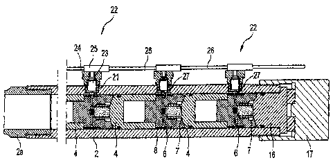
CA 02525013 2005-11-07
8
Several receiving holes 21 for ignition charges 22 are
provided in the outer wall of the barrel in its longitudinal
direction, these ignition charges having each a pyrotechnical
ignition means 23 as they are e.g. known for igniting safety
means in motor vehicles such as air bags or belt tighteners
and are e.g. described in the European patent 1,000,310 of
Applicants. The ignition means 23 have in each case an
ignition chamber in a housing that is filled with ignition
material. Contact pins project into the ignition chamber,
which are connected in the ignition chamber by means of a
resistance wire. The ignition means are received in a housing
24 which is insertable in a receiving hole 21. An ignition
connector 24 is slipped onto each housing 24, which
establishes the electric contact with the contact pins of the
individual ignition means. The connectors 25 are connected
with each other by means of cables 26, the cable leading to
the first ignition connector 25 leading to an ignition means
(not shown) which sequentially provides the electric ignition
pulses for the individual ignition charges 22. The entire
unit consisting of ignition charges, cables and ignition
means is only placed onto the barrel when the weapon is used.
An ignition duct 27 leads radially into the interior of the
barrel 2 from the bottom of each receiving opening 21 for an
ignition charge 22. The ignition duct ends in the area of the
annular duct 8 of a sub-projectile 4.
If the individual ignition charges 22 are sequentially
ignited, the ignition flame of the respective ignition charge
22 enters the annular duct 8 via the ignition duct 27, the
extension of the twist-band 11 being punctured. Then, the
ignition flame enters the branch ducts 9 and ignites the
CA 02525013 2005-11-07
9
ignition charge 10 of the propellant charge 7 which is also
ignited by this. After the ignition of the propellant charge
the propellant gases flow over the overflow openings into the
pressure chamber 12, as well, until such a defined pressure
is exerted onto the bottom of the respective sub-projectile 4
that the rated break point 7 between the propellant charge
and the subsequent sub-projectile is broken and the front
sub-projectile 4 is ejected from the barrel 2.
The area of the barrel 2 in which the sub-projectiles 4 are
located is a smooth barrel which is adjoined by a barrel
section 2a with twist grooves 28 (cf. Fig. 5). As soon as the
respective sub-projectile reaches the area 2a of the barrel
with the twist grooves, they engage the twist-band 11 so that
the sub-projectile is caused to rapidly rotate in order to
stabilize its flight position.
A second example of embodiment of a rapid-fire weapon 1 is
shown in Fig 5. Again, each sub-projectile 4 comprises a
casing 5' at its rear, which has an annular chamber 31 being
open towards the rear, in which the propellant charge 6 is
mounted. The casing 5' comprises a central anvil 32 with
which the respectively foremost sub-projectile is supported
on the sub-projectile located behind it.
The casing 5' of each sub-projectile is extended towards the
rear and provided with an internal thread which engages into
an external thread on the head of the sub-projectile located
behind it and/or the blind flange 16'. This thread forms a
defined rated break point 7'. In this design, as well, the
volume of the propellant charge is defined and limited.
CA 02525013 2005-11-07
Upon the ignition of the individual ignition charges 22 the
casing 5' which is formed with a rated break point 33 that is
formed as an annular groove is punctured by the ignition
flame of the ignition charge 21 which then directly ignites
the propellant charge 6. As soon as the pressure stipulated
by the rated break point 7' is reached and the rated break
point 7' breaks, the sub-projectile is ejected from the
barrel 2 in a controlled manner and with reproducible
conditions and is set rotating by the twist grooves 28 in the
area 2a of the barrel.