Note: Descriptions are shown in the official language in which they were submitted.
T0463 SPD7W/TAN CA 02525082 2005-11-07
VALVE
BACKGROUND
The present invention relates to a valve for installation in high-pressure gas
piping systems, for example, in fuel cell systems, in which a valve disc and a
valve
seat are brought into close contact via a sealing member composed of an
elastic
material and provided on one of them.
Valves in which a sealing member composed of an elastic material such as
l0 rubber is disposed on either a valve disc or a valve seat is known as the
conventional valve designed for high-pressure fluids (for example, see
Japanese
Patent Laid-open Publication No. 2003-240149 (Page 4 and FIG. 2) and Japanese
Utility Model Laid-open Publication No. H5-73368 (Page 9 and FIG. 2). Among
such valves, in pilot electromagnetic valves described in Japanese Patent Laid-
open Publication No. 2003-240149, in which the sealing member is disposed on
the valve seat, the sealing member and valve disc are so formed that the
sealing
member pressed by the high-pressure fluid when the valve disc is open will not
be
damaged by the deformation in the flow direction of the fluid.
However, in such conventional valves, if a state is assumed with a large
difference in pressure between the primary side and the secondary side, when
the
valve is opened, the fluid rapidly flows to the secondary side and a large
force is
rapidly applied by the fluid to the sealing member. The resultant problem is
that the
sealing member, which is an elastic substance, easily undergoes large
deformation
that easily leads to loss of durability.
Increasing hardness of the sealing member is apparently the simplest way to
resolve the above-described problem. However, if a state is assumed in which
the
1
T0463 SPD7W/TAN CA 02525082 2005-11-07
difference in pressure between the primary side and secondary side is small,
the
force applied to the sealing member when the valve is closed is insufficient
and this
time the sealing capability is easily lost.
SUMMARY
It is an object of the present invention to provide a valve in which
durability of
a sealing member made from an elastic material can be increased and sealing
capability can be advantageously maintained over a wide range from a large
differential pressure to a low differential pressure.
To attain the object, the present invention provides a valve in which a valve
disc (element) and a valve seat are brought into close contact via a sealing
member composed of an elastic material (substance) and provided at the valve
disc or valve seat. This valve comprises a throttle section defined by the
shape of
at least one of the valve disc and valve seat and narrowing a flow passage
formed
therebetween. The throttle section is provided near the sealing member.
With such a configuration, the force of the fluid acting upon the sealing
member is relaxed, because the throttle section provided near the sealing
member
causes pressure loss in the fluid. As a result, even in the case of a high
difference
in pressure between the primary side and secondary side, durability of the
sealing
member can be advantageously increased. Another result is that sealing
capability
can be maintained over a wide range from a high differential pressure to a low
differential pressure, while maintaining the degree of freedom in designing
the
properties such as hardness of the sealing member.
Here, any one or two of the locations upstream and downstream of the
sealing member are included in the "near the sealing member". For example,
when
2
T0463 SPD7W/TAN CA 02525082 2005-11-07
the sealing member has an annular shape, the throttle section is provided near
the
sealing member by disposing the throttle section either or both of on the
inner side
and outer side in the radial direction of the sealing member.
The throttle section can be defined by the shape of only one of the valve disc
and valve seat, or by establishing the relationship between the shapes of the
two.
The valve according to the present invention is applicable to both the direct
operated systems and the pilot systems, and the operation system thereof may
be
manual or based on a variety of actuators. For example, an electromagnetic
valve
can be obtained.
In one preferred mode for carrying out the invention, the flow passage
narrowed by the throttle section is so set that narrowing preferentially
proceeds in
the flow passage in close proximity to the sealing member during the closing
operation of the valve disc.
With such a configuration, during the closing operation of the valve disc, a
sufficient pressure loss is generated and durability of the sealing member is
advantageously increased. Meanwhile, when the valve is opened, pressure loss
is
effectively avoided and a sufficient (prescribed) flow rate can be ensured in
the
inner flow passage of the valve.
Another valve according to the present invention is a valve in which a valve
disc and a valve seat are brought into close contact via a sealing member
composed of an elastic material and provided at the valve disc or valve seat.
This
valve comprises a flow passage leading from an inflow port to an outflow port
through the location of the sealing member, and a pressure loss section
provided in
close proximity to the sealing member and impeding the flow of the fluid by
partially
reducing the cross section area of the flow passage.
3
T0463 SPD7W/TAN CA 02525082 2005-11-07
With such a configuration, the force of the fluid acting upon the sealing
member is relaxed, in the same manner as described above. As a result, even in
the case of a high difference in pressure between the primary side and
secondary
side, durability of the sealing member can be advantageously increased.
In this case, it is preferred that the pressure loss section reduces partially
and gradually the cross section area of the flow passage following the
movement of
the valve disc in the closing direction.
In those cases, it is preferred that the pressure loss section is defined by
the
shape of the valve disc and/or the valve seat.
Yet another valve according to the present invention is a valve in which a
valve disc and a valve seat are brought into close contact via an annular
sealing
member composed of an elastic material and provided at the valve disc or valve
seat. The valve disc comprises a first surface facing the valve seat, and a
first
peripheral surtace connected to the first surface. The valve seat comprises a
second surface facing the first surface, and an annular protrusion protruding
from
the second surface toward the first peripheral surface in a position facing
the first
peripheral surface. The sealing member is provided at one of the first surtace
and
the second surface and configured so that it can be brought into close contact
with
the other of the first surface and the second surface. A flow passage between
the
first peripheral surface and the annular protrusion comprises a flow passage
that is
set to have a cross section area that is reduced with respect to that of a
flow
passage between the first surtace and the second surface.
Preferably, in the flow passage that is set to have a reduced cross section
area, the ratio of reduction of the cross section that follows the closing
operation of
the valve disc is larger than that in the flow passage between the first
surface and
the second surtace.
4
T0463 SPD7W/TAN CA 02525082 2005-11-07
Preferably, the annular protrusion has a second peripheral surface that is
connected to the second surface and can face the first peripheral surface. The
flow
passage that is set to have a reduced cross section area is at least part of
the flow
passage between the first peripheral surface and the second peripheral
surface.
Further preferably, the first peripheral surface is composed of a tapered
peripheral surface and the peripheral surface is composed of an inversely
tapered
peripheral surface inclined toward the valve disc.
More preferably, the relationship R~ > R2 is satisfied, where R~ stands for a
distance to the crossing section of the first surface and the tapered
peripheral
l0 surface and R2 stands for a distance to the crossing section of the second
surface
and the inversely tapered peripheral surface.
Preferably, the relationship 6~ > A2 is satisfied, where 8~ stands for an
inclination angle of the tapered peripheral surface with respect to the axis
center of
the valve disc and 6z stands for an inclination angle of the inversely tapered
peripheral surface with respect to the axis center of the valve disc.
Preferably, the relationship H3 < H4 is satisfied, where H3 stands for a
distance between the first peripheral surface and the annular protrusion and
H4
stands for a distance between the first surface and the second surface.
In this case, it is preferred that the reduction ratio of H3 is set to become
higher than the reduction ratio of H4 during the closing operation of the
valve disc.
Furthermore, with the above-described mode for carrying out the present
invention, it is preferred that the annular protrusion has a second peripheral
surface
that is connected to the second surface and can face the first peripheral
surface
and an annular surface connected to the second peripheral surface and parallel
to
the second surface.
5
T0463 SPD7W/TAN CA 02525082 2005-11-07
In those cases, it is preferred that the first surface and the second surface
is
parallel to each other.
In those cases, it is preferred that the sealing member protrudes from one of
the first surface and the second surface toward the other.
With the above-described valve according to the present invention, because
the rapid fluid flow acting upon the sealing member is restricted by the
throttle
section, durability of the sealing member can be increased and adequate
sealing
capability of the sealing member can be maintained when the difference in
pressure between the primary side and secondary side is high or low, that is,
l0 regardless of the difference in pressure between the primary side and
secondary
side.
DESCRIPTION OF DRAWINGS
FIG. 1 is an explanatory drawing showing in a cross-sectional view the
general features of the valve according to Embodiment 1;
FIG. 2 is an explanatory drawing showing in a cross-sectional view the
general features of the valve according to Embodiment 1;
FIG. 3 is an explanatory drawing showing in a cross-sectional view the
general features of the valve according to Embodiment 1;
FIG. 4 is an explanatory drawing showing in a cross-sectional view the
general features of the valve according to Embodiment 1;
FIG. 5 is an explanatory drawing showing in a cross-sectional view the
general features of the valve according to Embodiment 2;
FIG. 6 is an explanatory drawing showing in a cross-sectional view the
general features of the valve according to Embodiment 3;
6
T0463 SPD7W/TAN CA 02525082 2005-11-07
FIG. 7 is an explanatory drawing showing in a cross-sectional view the
general features of the valve according to Embodiment 4;
FIG. 8 is an explanatory drawing showing in a cross-sectional view the
general features of the valve according to Embodiment 5;
FIG. 9 is an explanatory drawing showing in a cross-sectional view the
general features of the valve according to Embodiment 6;
FIG. 10 is an explanatory drawing showing in a cross-sectional view the
general features of the valve according to Embodiment 7;
FIG. 11 is an explanatory drawing showing in a cross-sectional view the
general features of the valve according to Embodiment 8;
FIG. 12 is an explanatory drawing showing in a cross-sectional view the
general features of the valve according to Embodiment 9;
FIG. 13 is an explanatory drawing showing in a cross-sectional view the
general features of the valve according to Embodiment 10;
FIG. 14 is an explanatory drawing showing in a cross-sectional view the
general features of the valve according to Embodiment 11;
FIG. 15 is an explanatory drawing showing in a cross-sectional view the
general features of the valve according to Embodiment 12;
FIG. 16 is a schematic cross-sectional view illustrating an example of a high-
pressure tank using an embodiment of the valve according to the present
invention;
and
FIG. 17 is an enlarged cross-sectional view illustrating the main portion of
the tank shown in FIG. 16.
DETAILED DESCRIPTION
7
T0463 SPD7W/TAN CA 02525082 2005-11-07
A valve of the preferred embodiment of the present invention will be
explained below with reference to the appended drawings. The valve shuts a
flow
passage for a fluid such as a high-pressure gas via a sealing member and is
assembled mainly in a piping system of hydrogen gas or oxygen gas of a fuel
cell
system. In the explanation provided below, the structure surrounding the
sealing
member will be explained in greater detail with a pilot-type electromagnetic
valve as
an example. FIG. 1 to FIG. 15 show schematically the left half, with respect
to a Y-
~-Y2 axis as a central axis, of the structure surrounding the sealing member.
Embodiment 1
FIG. 16, as mentioned above, is a schematic cross-sectional view illustrating
an example of a high-pressure tank using an embodiment of the valve according
to
the present invention. A high-pressure tank 200 comprises a tank body 201
having
as a whole an almost cylindrical shape, a sleeve 202 (mouthpiece) provided at
one
end or both ends of the tank body in the longitudinal direction thereof, and a
valve
assembly 203 detachably attached to the sleeve 202. The inside of the tank
body
201 serves as a storage space 204 for retaining a fluid such as a gases of
various
types, for example, natural gas or hydrogen gas, under a high pressure. When
such a high-pressure tank 200 is employed in a fuel cell system, for example,
hydrogen gas at 35 MPa or 70 MPa or CNG Compressed Natural Gas) at 20 MPa
is sealed and held inside the storage space 204.
The below-described valve 100 having a valve disc 1, a valve seat 2, and a
sealing member 5 that is the object of the present invention operates with a
fluid
such as gas at a pressure of at least 1 MPa. The valve 100 preferably operates
8
T0463 SPD7W/TAN CA 02525082 2005-11-07
with a fluid at a pressure of 3 MPa and higher, even more preferably at a
pressure
of 35 MPa and higher.
The tank body 201 has a double-wall structure in which an inner liner 210
(inner shell) having gas barrier properties is coated on the outside with a
shell 212
(outer shell) composed of a FRP. The liner 210 is formed, for example, from a
resin such as high-density polyethylene. However, the tank body 201 may be
also
a metal container made, for example, from an aluminum alloy. Furthermore, the
gas retained inside the tank body 201 can be supplied to the storage space 204
from an external gas line via a valve assembly 203 attached to the sleeve
(mouth
l0 piece) 202 and released to the external gas line via this valve assembly
203.
The region between the sleeve 202 and tank 200 is air-tightly sealed with a
plurality of sealing members (not shown in the figures). Furthermore, an
external
thread 216 is formed on the outer peripheral surface of the open portion of
the
sleeve 202. The valve assembly 203 is connected by screwing to the open
portion
of the sleeve 202 via the external thread 216. Furthermore, a flow passage 218
to
connect the external gas line to the storage space 204 is provided in the
valve
assembly 203.
A variety of pipe elements such as valves and couplings are integrally
assembled in the valve assembly 203. For example, the valve assembly 203
2o comprises an electromagnetic valve 100 serving as a main valve disposed on
the
flow passage 218 and a regulator (valve; not shown in the figure) disposed on
the
flow passage 218 in series with the electromagnetic valve 100. The
electromagnetic valve 100 and regulator may be also arranged in reverse order,
and the electromagnetic valve 100 may be installed and connected to the sleeve
202 separately from the valve assembly 203, rather that being assembled
integrally
with the valve assembly 203.
9
T0463 SPD7W/TAN CA 02525082 2005-11-07
FIG. 17 is an enlarged cross-sectional view illustrating the main portion
shown in FIG. 16. In FIG. 17 and the below-described FIG. 1 to FIG. 15, the
components are arranged so that that the side of the storage space 204, that
is, the
upstream side, is in the upper part of the figure.
As shown in FIG. 16 and FIG. 17, the electromagnetic valve 100 comprises
a valve disc 1 connected to a solenoid unit 110 for driving, a valve seat 2
disposed
opposite the valve disc 1 at a certain distance therefrom, and a sealing
member 5
from an elastic material provided at the valve disc 1. When driven by the
solenoid
unit 110, the valve disc 1 is moved to and from the valve seat 2. If the valve
disc 1
is brought into close contact with the valve seat 2 via the sealing member 5
and a
close contact state (closed valve state) is assumed, the storage space 204 and
flow
passage 218 are isolated and sealed.
In the electromagnetic valve 100, the outer shell thereof is composed of a
housing 120. In the housing 120, an inflow port G1 is provided upstream of the
valve disc 1 and an outflow port G2 connected to the fluid flow passage 218 is
provided downstream of the valve seat 2. The fluid that flows through the
electromagnetic valve 100 flows in from a high-pressure side 3 on a primary
side
via the inflow port G1, passes through the flow passage formed between the
valve
disc 1 and valve seat 2, and flows out from the low-pressure side 4 on the
secondary side to the outflow port G2.
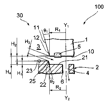
FIG. 1 is schematic cross-sectional view of the electromagnetic valve 100
showing on an enlarged scale the main components shown in FIG. 17. As shown
in FIG. 1, the valve disc 1, valve seat 2, and sealing member 5 are disposed
coaxially on the Y~-Y2 axis. The passage 6 connected to the outflow port is
formed
on the Y~-YZ axis.
T0463 SPD7W/TAN CA 02525082 2005-11-07
The valve disc 1 is formed from a non-elastic substance (material) such as a
metal and can be moved in the direction of the Y~-YZ axis, which is a central
axis
thereof. The valve disc 1 comprises a front surface 10 (first surface)
perpendicular
to the Y~-Y2 axis and an inclined surface 11 (first peripheral surface or
tapered
peripheral surface) integrally connected in a tapered configuration from the
front
surface 10 to the base side. The valve disc 1 has a truncated cone shape as a
whole. The front surface 10 of the valve disc 1 has a radius R~ from the Y~-YZ
axis
as a center, and the inclined surface 11 forms the prescribed angle A~ with
the Y~-
Y2 axis.
The valve seat 2, similarly to the valve disc 1, is formed from a non-elastic
substance (material) such as a metal and, as a whole, is formed from an almost
annular member provided with a step. The valve seat 2 comprises a seat surface
21 (second surface) that is parallel to the front surtace 10 of the valve disc
1 and
faces it, a tilted surface 22 (second peripheral surface or inversely tapered
peripheral surface) that is integrally connected to the seat surface 21 and
inclined
toward the valve disc 1, and a non-seat surface 23 that is integrally
connected to
the tilted surface 22 and parallel to the seat surface 21. The non-seat
surface 23 is
set at a distance H~ in the Y~-Y2 axis direction from the seat surface 21. An
annular
protrusion that protrudes from the seat surface 21 to the front surface 10 is
constituted by the tilted surface 22 and non-seat surface 23, and this annular
protrusion faces the inclined surface 11.
The seat surface 21 of the valve seat 2 has a radius RZ from the Y~-Y2 axis
as a center, and the tilted surface 22 thereof forms the prescribed angle A2
with the
Y~-YZ axis. In this case, the radius R2 is set slightly larger than the radium
R~, and
the angle 62 is set somewhat smaller than the angle 6~. A throttle section 30
where
the flow passage on the outer side in the radial direction of the sealing
member 5 is
11
T0463 SPD7WITAN CA 02525082 2005-11-07
narrowed, of the entire flow passage formed between the valve disc 1 and valve
seat 2, is defined by those shape parameters (6~, 62, R~, R2) of the valve
disc 1 and
valve seat 2.
The throttle section 30 is configured to narrow the flow passage inside the
valve 100 leading from the inflow port G1 (high-pressure side 3) to the
outflow port
G2 (low-pressure side 4) over the circumferential direction on the upstream of
the
vicinity of the sealing member 5. That is, the flow passage in the throttle
section 30
is set to have a cross section area less than the flow passage between the
front
surface 10 and seat surface 21. The throttle section 30 functions as a
pressure loss
section where the fluid flow is obstructed by partially reducing the cross
section
area of the flow passage inside the valve 100.
A specific region defining the throttle section 30 is a crossing section 25 of
the tilted surface 22 and non-seat surface 23 on the side of the valve seat 2.
On
the other hand, on the side of the valve disc 1, a region defining the
throttle section
30 is set as a region 12 of the inclined surtace 11 positioned at the shortest
distance from the crossing section 25, but this region 12 varies according to
the
position of the valve disc 1.
Thus, as shown in FIG. 1, when the valve is open and the valve disc 1 and
valve seat 2 are sufficiently spaced apart, the region 12 on the side of the
valve
disc 1, which defines the throttle section 30, is set as a crossing section of
the front
surface 10 and the inclined surface 11. On the other hand, when the valve is
opened (during closing operation) and the valve disc 1 is comparatively close
to the
valve seat 2, as shown in FIG. 3, the region 12 on the side of the valve disc
1,
which defines the throttle section 30, is set as the prescribed region of the
inclined
surtace 11 crossed by a perpendicular dropped from the crossing section 25 of
the
valve seat 2 to the inclined surface 11.
12
T0463 SPD7W/TAN CA 02525082 2005-11-07
In the explanation provided hereinbelow, the distance between the crossing
section 25 of the valve seat 2 defining the throttle section 30 and the region
12 of
the valve disc 1 will be taken as H3. For the convenience of explanation, H3
will
sometimes mean the flow passage (gap) narrowed by the throttle section 30, or
the
size thereof or the cross section surface area of the flow passage. Similarly,
the
distance H4 between the front surface 10 of the valve disc 1 and the seat
surface
21 of the valve seat 2 is obtained by adding the aforementioned H~ to the
distance
H2 between the front surface 10 of the valve disc 1 and the non-seat surface
23.
Similarly, for the convenience of explanation, H4 will sometimes mean the flow
l0 passage (gap between the front surface 10 and the seat surface 21 ) in
close
proximity the sealing member 5 apart from the throttle section 30, or the size
thereof or the cross section surface area of the flow passage.
Because the throttle section 30 is formed described above, when the valve is
open as shown in FIG. 1, H3 is set less than H4. Furthermore, during the
closing
operation of the valve disc 1 illustrated by FIG. 2 and FIG. 3, H3 and H4
decrease,
while maintaining the H3 < H4 relationship, but H3 is set so as to become
narrower
at a rate greater than that of H4. Thus, the settings are such that the
reduction ratio
of H3 per unit time is larger than the reduction ratio of H4 during the
closing
operation of the valve disc 1. As a result, during the closing operation of
the valve
disc 1, a sufficient pressure loss is generated in the throttle section 30 and
the fluid
force acting on the sealing member 5 is relaxed.
The sealing member 5 is formed from an elastic material such as rubber and
has an annular shape with the Y~-YZ axis as a center. The sealing member 5 is
provided near the throttle section 30 and protrudes from the front surface 10
of the
valve disc 1 toward the seat surface 21. The sealing member 5 is so configured
that the surface thereof that faces the seat surface 21 of the valve seat 2 is
a flat
13
T0463 SPD7W/TAN CA 02525082 2005-11-07
surface parallel thereto. When the valve is closed, this surface is brought
into the
close contact with the seat surface 21, shutting the flow passage. The sealing
member 5 provides for air-tight sealing between the high-pressure side 3 and
low-
pressure side 4.
The operation of the electromagnetic valve 100 configured as described
before will be explained below with reference to FIG. 1 to FIG. 4. When the
valve is
opened as shown in FIG. 1, the fluid flows from the high-pressure side 3 to
the low-
pressure side 4 through H3 and H4. The flow rate of the fluid in this process
mainly
depends on H3.
As shown in FIG. 2, after a transition is made to the closing operation of the
valve disc 1, the fluid undergoes pressure loss and the flow rate thereof is
inhibited
when it passes through H3 that was narrowed faster than H4 and then flows into
H4.
On the other hand, because the H3 < H4 relationship is maintained, the flow
velocity
in H4 decreases by comparison with that in H3. Therefore, the force with which
the
fluid acts upon the sealing member 5 positioned in H4 is reduced by comparison
with that acting without the throttle section 30. Note that the flow rate of
the fluid at
this time mainly depends on H3.
After the closing operation of the valve disc 1 has been further advanced to
the final stage, as shown in FIG. 3, the sealing member 5 abuts against the
seat
surface 21 of the valve seat 2, but at this time the fluid undergoes a very
large
pressure loss and the flow rate thereof is greatly restricted when it passes
through
H3. Therefore, the force with which the fluid acts upon the sealing member 5
is
greatly reduced by comparison with that acting without the throttle section
30.
Furthermore, when the pressure on the contact surface of the sealing member 5
and seat surface 21 becomes equal to or higher than the pressure of the high-
14
T0463 SPD7WITAN CA 02525082 2005-11-07
pressure side 3, an air-tight seal is provided between the high-pressure side
3 and
low-pressure side 4.
Thus, in the process of closing the valve disc shown in FIG. 2 and FIG. 3,
the force of the fluid acting upon the sealing member 5 is gradually relaxed.
Therefore, durability of the sealing member 5 can be advantageously increased.
Furthermore, in the closed state shown in FIG. 4, the front surface 10 of the
valve
disc 1 and the seat surface 21 of the valve seat 2 come into close contact,
flattening the squeeze of the sealing member 5 and providing for air-tight and
reliable sealing between the high-pressure side 3 and low-pressure side 4. At
this
time, the settings are such that H4 becomes zero or almost zero and a slight
H3 is
present. The settings may be also such that the crossing section 25 on the
side of
the valve seat 2 is brought into contact with the inclined surface 11 of the
valve disc
1 and H3 becomes zero.
Furthermore, during the closing operation of the valve disc 1 shown in FIG. 2,
the contact flatness of the valve disc 1 against the valve seat 2 and the
concentricity thereof are increased based on the principle of self centering
induced
by the fluid flow. More specifically, as H3 decreases following the closing
operation
of the valve disc 1, the valve disc 1 is moved by the fluid in the Y~
direction of the
Y~-Y2 axis and to the central axis. As a result, the closing operation is
performed,
while automatically providing for concentricity and maintaining the contact
flatness
of the valve disc 1 against the valve seat 2, and the movement speed in this
closing
operation is reduced.
As a result, the closing operation of the valve disc 1 can be pertormed with
good stability and the sealing member 5 and valve seat 2 can be brought into
contact, while relaxing the contact speed, as shown in FIG. 3. Therefore, when
the
sealing member 5 shown in FIG. 3 and FIG. 4 is in a state of contact with the
valve
T0463 SPD7W/TAN CA 02525082 2005-11-07
seat 2, the sealing member 5 contacts with against the valve seat 2 by a
uniform
force in the circumferential direction thereof, and in this aspect, a
contribution can
be made to improving the durability of the sealing member 5.
Furthermore, in the electromagnetic valve 100 of the present embodiment,
the force of the fluid acting upon the sealing member 5 is also relaxed by the
throttle section 30 during the opening operation of the valve disc, that is,
when the
valve disc 1 is operated according to the sequence of FIG. 4 -~ FIG. 3 ~ FIG.
2 -~
FIG. 1 that is not described herein in detail. Furthermore, in the open state
shown
in FIG. 1, pressure loss is effectively avoided and a sufficient flow rate is
ensured in
l0 the flow passage inside the valve.
The electromagnetic valves 100 of other embodiments of the present
invention will be explained below with reference to the appended drawings. The
explanation will be focused on the difference between Embodiment 1 and each
other embodiment. Components identical to the above-described components are
assigned with identical reference numerals and the explanation thereof is
omitted.
Embodiment 2
As shown in FIG. 5, in the electromagnetic valve 100 of Embodiment 2, the
sealing member 5 of Embodiment 1 is provided at the seat surface 21 of the
valve
seat 2. The arrangement position of the sealing member 5 in Embodiment 2 is
the
opposite of that in Embodiment 1, and the sealing member 5 is so configured
that it
can be brought into close contact with the front surface 10 of the valve disc
1.
Therefore, in this embodiment, the operation and effect identical to those of
Embodiment 1 can be attained too.
16
T0463 SPD7WITAN CA 02525082 2005-11-07
Embodiment 3
As shown in FIG. 6, in addition to the structural elements of Embodiment 1,
the electromagnetic valve 100 of Embodiment 3 comprises a throttle section 40
that
narrows the flow passage" downstream of the sealing member 5 provided between
the valve disc 1 and valve seat 2. This downstream throttle section 40 has the
same function as the upstream throttle section 30 of Embodiment 1, but is
mainly
defined by a needle-like protruding section 41 protruding from the front
surface 10
of the valve disc 1. The protruding section 41 which axis corresponds to the
Y~-Yz
axis is configured to be received in the passage 6.
In the downstream throttle section 40, the tilted surface 11 of the protruding
section 41 corresponds to the inclined surface in the upstream throttle
section 30,
and the annular angular section 42 constituting the passage 6 corresponds to
the
crossing section 25 of the valve seat 2 in the upstream throttle section 30.
The flow
passage narrowed by the downstream throttle section 40 is so set that,
similarly to
the relationship of H3 and H4, narrowing preferentially proceeds in the flow
passage
(H4) in close proximity to the sealing member 5 during the closing operation
of the
valve disc 1. Furthermore, the cross section area of the flow passage narrowed
by
the downstream throttle section 40 is set smaller than the cross section area
of the
passage 6, and is so set that during the closing operation of the valve disc
1, it also
decreases, while maintaining the aforementioned relationship.
In the present embodiment, in addition to the operation and effect of
Embodiment 1, the pressure loss can be also generated in the throttle section
40
downstream of the sealing member 5, in particular during the closing operation
of
the valve disc 1. Therefore, the force of the fluid acting upon the sealing
member 5
17
T0463 SPD7W/TAN CA 02525082 2005-11-07
can be relaxed even more significantly. Therefore, durability of the sealing
member
can be further improved.
Embodiment 4
5
As shown in FIG. 7, in the electromagnetic valve 100 of Embodiment 4, the
sealing member 5 of Embodiment 3 is provided at the seat surface 21 of the
valve
seat 2. In the present embodiment, similarly to Embodiment 3, the throttle
sections
30, 40 are present in front and behind, that is, upstream and downstream of
the
l0 sealing member 5. Therefore, the operation and effect similar to those of
Embodiment 3 can be attained.
Embodiment 5
As shown in FIG. 8, in the electromagnetic valve 100 of Embodiment 5, the
upstream throttle section 30 is omitted from the structure of Embodiment 3
shown
in FIG. 6. Therefore, when the valve is opened, as shown in FIG. 8, the fluid
passes from the high-pressure side 3 through H4 and then through the flow
passage narrowed by the downstream throttle section 40 and flows to the low-
pressure side 4.
In the present embodiment, the pressure loss is generated via the operation
of only the throttle section 40 located downstream of the sealing member 5 and
the
flow rate of the fluid flowing into H4 can be restricted. However, the force
of the
fluid acting upon the sealing member 5 can be relaxed in the same manner as in
Embodiment 1. Therefore, in the present embodiment, too, the operation and
effect identical to those of Embodiment 1 can be attained.
18
T0463 SPD7W/TAN CA 02525082 2005-11-07
Embodiment 6
As shown in FIG. 9, in the electromagnetic valve 100 of Embodiment 6, the
sealing member 5 of Embodiment 5 is provided on the seat surface 21 of the
valve
seat 2. The arrangement position of the sealing member 5 in Embodiment 6 is
the
opposite of the arrangement position in Embodiment 5, and the operation and
effect attained in Embodiment 6 are identical to those of Embodiment 5.
Embodiment 7
As shown in FIG. 10, in the electromagnetic valve 100 of Embodiment 7, the
throttle section 30 different from that of Embodiment 1 is formed. The
throttle
section 30 of the present embodiment is defined by the annular convex portion
51
formed so as to protrude downward from the front surface 10 of the valve disc
1
and a concave portion 52 formed annularly in the seat surface 21 of the valve
seat
2 so as to face the convex portion 51 and to be able to accommodate it.
With the throttle section 30 of the present embodiment, because the
pressure loss can be generated by narrowing the flow passage that is located
upstream of the sealing member 5, or near the sealing member 5, the force of
the
fluid acting upon the sealing member 5 can be relaxed and durability of the
sealing
member 5 can be increased in almost the same manner as in the above-described
embodiments. Furthermore, the shape elements defining the throttle section 30
may have an inverted configuration between the valve disc 1 and valve seat 2,
that
is, the concave portion 52 may be formed in the valve disc 1 and the convex
portion
51 may be formed in the valve seat 2.
19
T0463 SPD7W/TAN CA 02525082 2005-11-07
Embodiment 8
As shown in FIG. 11, in the electromagnetic valve 100 of Embodiment 8, the
sealing member 5 of Embodiment 7 is provided at the seat surface 21 of the
valve
seat 2. The arrangement position of the sealing member 5 in Embodiment 8 is
the
opposite of the arrangement position in Embodiment 7, and the operation and
effect attained in Embodiment 8 are identical to those of Embodiment 7.
Embodiment 9
As shown in FIG. 12, in the electromagnetic valve 100 of Embodiment 9, the
throttle section 30 of Embodiment 7 shown in FIG. 10 is provided downstream of
the sealing member 5. With the throttle section 40 of the present embodiment,
because the pressure loss can be generated by narrowing the flow passage that
is
located downstream of the sealing member 5, or near the sealing member 5, the
force of the fluid acting upon the sealing member 5 can be relaxed and
durability of
the sealing member 5 can be increased in almost the same manner as in
Embodiment 7.
Embodiment 10
As shown in FIG. 13, in the electromagnetic valve 100 of Embodiment 10,
the sealing member 5 of Embodiment 9 is provided at the seat surface 21 of the
valve seat 2 and the arrangement position thereof is the opposite of the
T0463 SPD7W/TAN CA 02525082 2005-11-07
arrangement position in Embodiment 9. Therefore, according to this embodiment,
the operation and effect of Embodiment 9 can be attained too.
Embodiment 11
As shown in FIG. 14, the electromagnetic valve 100 of Embodiment 11 is
equivalent to combination of Embodiment 7 shown in FIG. 10 and Embodiment 9
shown in FIG. 12. Thus, in the electromagnetic valve 100 of the present
embodiment, the throttle sections 30, 40 having convex section 51 and concave
to section 52 are provided both upstream and downstream of the sealing member
5,
and in this case the convex section 51 is formed on the valve disc 1.
According to
this embodiment, the force of the fluid acting upon the sealing member 5 can
be
relaxed to a greater extent and durability of the sealing member 5 can be
further
increased by comparison with those obtained with a single throttle section.
Embodiment 12
As shown in FIG. 15, in the electromagnetic valve 100 of Embodiment 12,
the sealing member 5 of Embodiment 11 is provided at the seat surface 21 of
the
valve seat 2 and the arrangement thereof is the opposite of the arrangement
position in Embodiment 11. Therefore, according to this embodiment, the
operation
and effect of Embodiment 11 can be attained too.
21