Note: Descriptions are shown in the official language in which they were submitted.
CA 02525226 2005-11-08
WO 2004/098267 PCT/NL2004/000304
Device for rolling ut~/rolling down a shade
The present invention relates to a device for rolling up/rolling down two
shades (11, 12, 33, 34) to/from a respective rotatable tube (9, 10, 32),
comprising a
single drive motor (3), a transmission providing connection between said drive
motor
and each of said tubes (9, 10, 32), a coupling being provided between one of
said
tubes and said drive motor.
Such a device is disclosed in the international patent application FCT/NL
02/00792 and provides a reliable functioning winding system for a shade,
allowing
accurately adjustment of the starting and end position and which can be
effective
during long time i.e. many years, without failure.
To that end the device described therein comprises a drive motor being fixedly
connected to the frame. Between the drive motor and the tube a drive shaft is
provided
being rotatable by the drive motor, whilst on the drive shaft in the direction
of its axis
displaceable and non-rotatable relative to said frame a transmission device is
provided
connected to said tube for transmitting the rotating movement from the drive
shaft to
said tube.
The improvement obtained results from the fact that no longer use is made of
an expensive tube motor that is susceptible to damage and is difficult to
install. A
simple motor that is immovably connected to the frame is used instead. By
means of
transmission devices that may be present, a drive shaft, which will be fitted
vertically
in the case of vertically moving shading, is provided. The transmission device
described above moves up or down in the vertical direction along this drive
shaft. This
vertical movement is imposed by the rolling up or rolling down of shading on
the tube
connected to the transmission device. This tube preferably extends in a
direction
perpendicular to the drive shaft.
The invention aims to improve the device according to the invention such that
a more flexible use and control is possible.
This aim is realized in that said coupling comprises an electrically
operatable
clutch, which can be switched between an uncoupled and coupled position by
operating means for said clutch, a control uiut (55) being provided having an
input for
signals with regard to parameters of the surroundings, such as temperature,
light,
moisture, wind force and the like, and/or with regard to the condition of the
shade,
such as unrolled length and the like, for controlling said operating means.
CA 02525226 2005-11-08
WO 2004/098267 PCT/NL2004/000304
2
Through a control unit the shade can automatically be controlled in the
desired
mode. Both the conditions inside and outside the greenhouse can be taken into
account.
The device according to the invention can be used in any system, wherein at
least two shades are operated by a single drive motor. By providing at least
one
electrically operatable clutch, control of at least one of said shades can be
made
independent of the movement of the drive motor. Preferably each of the shades
is
provided with its own electrically operatable coupling comprising a clutch.
Preferably, the device according to the invention comprises a system as
disclosed in the international patent application PCT/NL 02100792.
Furthermore the operating means can comprise memory means for storing data
with regard to the position of the tube and/or the length of the unrolled tube
dependent
of values corresponding with data from the surroundings and/or the condition
of the
shade.
By fitting in the transmission device a clutch that is effective when there is
overloading, i.e. an adjustable clutch, it is possible during continuous
rotation of the
drive shaft to limit the maximum torque per transmission device (adjustable
mar. roll-
up force) and also to make this limitation take effect by means of an
adjustable stop
(beginning/end). In both cases the clutch becomes active, with the result that
moment-
limited disconnection of the roller tube relative to the drive shaft occurs.
Through use
of a braking feature between motor and tube in combination with the adjustable
slip-
action clutch, it is ensured that in the rolled-up position or in an
intermediate position
the roll-up tube does not roll out in an uncontrolled manner. Such a braking
feature
can be achieved with, for example a worm wheel.
However, it is also possible to provide the braking property in the drive
motor,
so that a relatively simple transmission in the transmission device will
suffice.
For example, it may furthermore be decided not to close, or only to close
partially, one of three shades situated one above the other, while the others
are in fact
fully closed. It is likewise possible with the construction according to the
present
invention periodically to ensure that shades are fully closed by periodically
moving
the drive shaft, so that any shade that is not fully closed will now be fully
closed. This
also applies, of course, to opening.
If the output shaft of the transmission device is rigidly connected to the
tube
on which the shade is received, basically no guidance of the transmission
device or
CA 02525226 2005-11-08
WO 2004/098267 PCT/NL2004/000304
3
support for receiving the rotational momentum is necessary. These forces can
be
received by the tube. It is possible to independently guide the transmission
in other
cases along the frame or greenhouse or the like.
The device described above for rolling up and rolling down shades can also be
S used in the case of a so-called twin shade, i.e. a tube on which two shades
are rolled
on top of each other. ~ne of these shades is connected in the manner described
above
to an immovable fastening situated above it, while the other shade has a
weighted free
end and extends hanging downwards.
Furthermore the device can comprise at least a further shade having a further
inmovable top fastening and a, further rotatable tube that is movable in said
frame
construction, for receiving and unwinding shade and a further transmission
device
movable on said drive shaft in the direction of its axis and not rotatable
relative to said
drive shaft for transmitting the rotating movement from said drive shaft to
said further
tube, said further transmission device being provided with a further clutch.
With this invention it is possible to operate a number of devices, for example
situated one above the other, by means of one drive shaft. With this invention
it is also
possible to operate simultaneously by means of one drive shaft several devices
that
are situated one above the other and differ in terms of height and/or required
torque.
These devices may be situated between horizontal trusses of, for example, a
glasshouse. By means of the clutch described above and operating means to be
fitted
for it, such as stops, it is possible during rotation of the drive shaft to
make each
transmission device, and consequently each shade, perform exactly the right
movement, without overloading occurring. This means that a large number of
tubes
on which shading is wound can be operated by means of a single motor.
Furthermore, at least one further drive shaft can be operated by means of the
single motor.
It is possible to operate not only vertically moving shades, but also
horizontally fitted shades in this way. In this case the tube on which the
shade is
wound is kept taut by means of counterweights or another (spring) mechanism.
It is
possible to operate simultaneously with one drive motor not only horizontal
shades,
but also vertical shades or shades placed at an angle.
The invention also relates to a method for operating a device according to one
of the preceding claims comprising the steps of
CA 02525226 2005-11-08
WO 2004/098267 PCT/NL2004/000304
4
determining the value of a surrounding parameter such as temperature, light,
moisture, wind strength, time and the like,
selecting based on this values) a position of the tube and/or the length of
the
unrolled shade,
energizing the drive for rotating of the tube for unrolling or rolling the
shade,
energizing the operating means for slippage of the slip clutch when the
desired
position of the tube, and/or the desired length of the unrolled shade is
reached.
The method also relates to energizing of other operating means for slipping of
further slip clutches when the desired position of the fbarrtther tube and/or
the desired
length of the unrolled further shade has been reached.
More particular if several shades are operated by a single drive the
advantages
of the invention are considerable. Such shades can be operated in different
ways,
whilst a single drive is necessary. Operation can be realised for example
based on
energy saving. In green houses there are for example drive tubes at the inner
side of
the facade in the lower portion thereof. In such a case the Iower shade can
remain
unrolled to prevent energy losses in outward direction. However, the higher
positioned shades can be rolled up completely or partially in order to
transmit as much
light as possible. Such an operation can be dependent from the measured
outdoor
temperature, time of the day and the like being pre-programmed in a control
unit.
The invention will be explained in greater detail below with reference to
exemplary embodiments illustrated in the drawing, in which:
Fig. 1 shows diagrammatically in elevation a part of a glasshouse construction
provided with the assembly as described in PCT/NL02/00792;
Fig. 2 shows a detail of the transmission device according to Fig. 1;
Fig. 3 shows a cross section along the line III-III in Fig. 2; and
Fig. 4 shows a variant of the shade according to the invention illustrated
diagrammatically,
Fig. 5 a view of the device according to the invention;
Fig. 6 a plan view, partially in cross section, of a transmission as used in
the
device according to fig. 5 and according to line VI-'VI in fig. 7;
Fig. 7 a front view, partially in cross section, of a transmission as shown in
fig.
6; and
Fig. 8 a side view of the transmission as such.
CA 02525226 2005-11-08
WO 2004/098267 PCT/NL2004/000304
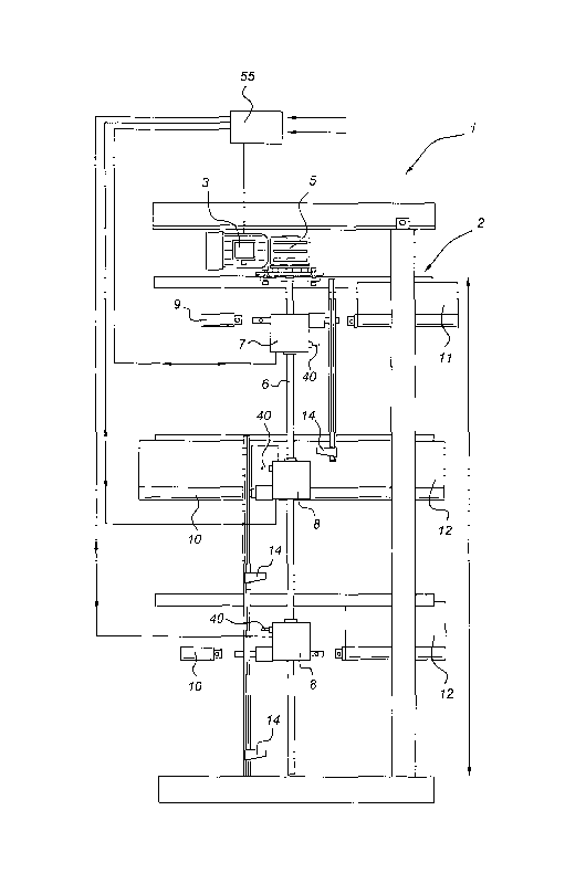
In Fig. 1 the assembly as described in PCT/NL02/00792 is indicated in its
entirety by 1. The frame of the glasshouse is shown diagrammatically by 2. It
is easily
possible to use a separate frame for the construction according to the
invention, but in
the case of a glasshouse this was not found to be necessary. A motor 3 is
immovably
5 fastened to the frame construction 2. The auxiliary shaft 4. is present, and
a
substantially vertically extending drive shaft 6 is driven by way of a right-
angled
transmission 5. The drive shaft 6 extends through transmission devices 7 and 8
respectively, by means of which tubes 9 and 10 respectively are driven, for
the
purpose of moving shades 11 and 12 respectively. Stops 13 and 149 which can
interact
with the operating means 25 and 26 respectively shown in Fig. 2, are present.
The
abovementioned shades 11 and 12 are illustrated in Fig. 1 by a solid line to
the right
of the vertical section 28. It will be understood that shades may also be
present to the
left of said section, as partially shown.
Details of the transmission devices 7 and 8 respectively are shown in Figures
2
and 3. It can be seen from these figures that shaft 6 is provided with a
groove 1S
extending along its entire length. The transmission device is composed of a
box 17,
which by way of a guide 29 (see Fig. 3) can be slid along its own drive (shaft
6) and
the vertical T-section 28 of the frame construction 2.
Above gear sleeve 16, a sleeve 2I is provided, which, as can be seen from Fig.
3, is provided with a key-shaped proj ection 18, which means that sleeve 21 is
not
rotatable, but is slidable, relative to drive shaft 6. Sleeve 21 is provided
with a(n)
(adjustable) slip-action clutch 23, fitted corresponding to tooth system 24 on
gear
sleeve I6. By means of spring 22, tooth system 23 is driven to tooth system
24, so that
the rotary movement applied to sleeve 21 can be transmitted to gear sleeve 16.
If,
however, the load is too great, tooth systems 23 and 24 will move past each
other and
slip will occur. The moment of slip can be regulated by adjusting initial
tension in the
spring. It will be understood that slip or disconnection can be achieved in
another
way. The clutch formed in this way is indicated by 20.
Operating pins 25 and 26, which act upon lip 40 of pulley 27, are present.
During upwards or downwards movement, in the end position the pins 25 and
26 respectively are brought into contact with stops 13 and 14 respectively.
Said stops
consequently move inwards, and during the rotation of pulley 27 lip 40 will
come into
contact with the corresponding operating pin, with the result that slip
occurs. When
there is rotation in the other direction of the drive shaft, pulley 27 will be
able to make
CA 02525226 2005-11-08
WO 2004/098267 PCT/NL2004/000304
6
a complete, or alinost complete, revolution before lip 40 touches the
corresponding
pin, but owing to this complete, or alinost complete, revolution being made,
box 17 is
moved so far from the corresponding stop that the corresponding operating pin
is
moved back again, with the result that the movement can be carried out.
It can be seen from Figs. 1 - 3 that, on rotation of the motor 3, drive shaft
6 is
rotated. This causes the tubes 9, 10 to be rotated, so that the shade 1 I, I2
is wound up
or wound down until stop 13 or 14 respectively is reached. At that moment the
driving
connection between drive shaft 6 and tube 9 and 10 respectively is broken. In
other
words, the end positions of tube 9 and 10 respectively are determined by the
stops 13
and 14, and not by the ending of the rotation of the drive shaft 6. This makes
it
possible to connect a number of transmission devices one after the other on
drive shaft
6. Furthermore, a safety mechanism is provided. In the event of overloading,
the
clutch 20 described above will also function, so that no damage is caused to
the
shades or drive. By means of the (adjustable) friction, the clutch 20 also
prevents
further rotation of tubes 9 and 10 if tube 6 is brought to a standstill in a
position
before a stop.
A so-called twin shade is shown diagrammatically in Fig. 4. A central tube 32,
on which a double shade is wound, is present. This is indicated by 33 and 34.
Shade
33 extends upwards and is immovably fastened to the frame construction 2, like
the
shades 11 and 12. Shade 34 is provided with a weighted end, indicated by 35,
which
end is free, i.e. if desired moves upwards and downwards by way of a guide, by
gravity. Tube 32 can be put in the place of tube 9 or 10. The same effect can
be
obtained in this way.
In the embodiment shown in fig. 5-~ the device according to the invention is
shown. The parts corresponding with the parts in the embodiment of fig. 1-4
have
been provided with the same references. The motor 3 is now directly connected
to the
angular transmission 5, driving a substantial vertical drive shaft 6. The
transmissions
7, S each have an arm 9, abutting in the lower position of the tubes 9, 10 the
associated stop 14. Arm 40 can pivot around pin 41 to swivel the lever 42.
This lever
42 has two lever portions 43, 44 which can each be contacted with one side of
the
cams 45 being provided on the part 46 of the slip clutch 23. This part 46 is
connected
with shaft studs 56 through bevel gears 47, 4~ and belt transmission 49, 50.
The other
part 51 of the slip clutch is unrotatably connected with the drive shaft 60.
CA 02525226 2005-11-08
WO 2004/098267 PCT/NL2004/000304
7
As soon as the arm touches a stop 14, i.e. reaches the lower position of the
tubes 9, 10, one of the lever parts 43, 44 is moved downwardly, such that the
cam 45,
being nearest, is positioned there against. The drive shaft 6 and the part 51
of the slip
clutch continue to rotate, the part 51 slipping relative to the other part 46
of the slip
clutch. The tube 9, 10 is stopped such that the shade is not fiuther winded or
unwinded.
Such a slip effect of the slip clutch cannot only be obtained by touching of
the
arm 40 against a stop 14. Also in other positions of the tubes 9, 10 in height
direction
the arm 40 can be operated through both solenoids 52, 53. As indicated in fig.
7 and ~
the solenoids 52, 53 operate a shaft 54 extending there between, which is
connected
itself with the arm 40. By operating one or both solenoids 52, 53, the shaft
54 and so
the arm 40 is tilted. By providing an electrical signal to the solenoids 52,
53, the tube
9, 10 can be stopped in any desired height. The other tubes 9, 10 can continue
to move
or also be stopped depending from the control program. The tubes 9, 10 axe
axially
displaceable but unrotatably connected with the shaft studs 56 for compensate
differences in expansion.
This control can be controlled by the control unit 55 as shown in fig. 5. To
the
control unit 55 signals can be fed, relating to the outer surroundings or both
the outer
and inner conditions of the greenhouse in which the device according to the
invention
is used. It can relate to temperature, moisture, direction of wind, light and
the like.
Furthermore signals can be fed to the control unit 55 with regard to the
position of the
tubes 9, 10, the position of the transmissions, i.e. whether or not they are
in a slipping
or non-slipping condition and the like. Based on a pre-programmed control the
control
unit can subsequently control the motor 3 as well feed signals to the
solenoids 52, 53.
In this way the tubes 9, 10 can be adjusted on any desired height independent
from
each other. Associated therewith the shades 11, 12 can be unwinded or winded
at any
desired length independent from each other.
With the subject invention it is possible to operate with a single motor
different tubes for winding/unwinding of a shade whilst variations in height
and/or
tolerances can be compensated for. For example it is possible to connect
several drive
shafts with motor 3. In this way considerable savings can be obtained whilst
because
of the simple mechanical construction a longer service life than with tube
motors is
guaranteed. The above embodiment wherein the shades are displaced
horizontally,
can be realized particular simple by suspension to the gutters between the
roof
CA 02525226 2005-11-08
WO 2004/098267 PCT/NL2004/000304
8
structure of greenhouses. It is also possible at a curved roof structure to
connect a
number of shafts 6 through cardanic clutchs with each other and displace a
shade
therein between.
t~lthough the invention has been described above with reference to a preferred
embodiment, it will be understood by the person spilled in the art that it is
possible to
make numerous modifications, which spring to mind immediately after reading of
the
above, which are obvious to the person skilled in the art, and which lie
within the
scope of the appended claims. For instance, the drive shaft and/or the shades
may be
fitted in a non-vertical position, alternatives are available in the prior art
for obtaining
the same moment of resistance, and numerous possibilities and alternatives are
conceivable with regard to the use or otherwise and the design of the guide
section 2~.