Language selection

Search

Patent 2525678 Summary

Third-party information liability

Some of the information on this Web page has been provided by external sources. The Government of Canada is not responsible for the accuracy, reliability or currency of the information supplied by external sources. Users wishing to rely upon this information should consult directly with the source of the information. Content provided by external sources is not subject to official languages, privacy and accessibility requirements.

Claims and Abstract availability

Any discrepancies in the text and image of the Claims and Abstract are due to differing posting times. Text of the Claims and Abstract are posted:

  • At the time the application is open to public inspection;
  • At the time of issue of the patent (grant).
(12) Patent: (11) CA 2525678
(54) English Title: METHOD FOR THE PRODUCTION OF A CONNECTION FLANGE
(54) French Title: PROCEDE POUR FABRIQUER UNE BRIDE D'ASSEMBLAGE
Status: Expired and beyond the Period of Reversal
Bibliographic Data
(51) International Patent Classification (IPC):
  • E04H 12/08 (2006.01)
(72) Inventors :
  • WOBBEN, ALOYS (Germany)
(73) Owners :
  • ALOYS WOBBEN
(71) Applicants :
  • ALOYS WOBBEN (Germany)
(74) Agent: OYEN WIGGS GREEN & MUTALA LLP
(74) Associate agent:
(45) Issued: 2010-02-23
(86) PCT Filing Date: 2004-03-19
(87) Open to Public Inspection: 2004-12-09
Examination requested: 2005-11-14
Availability of licence: N/A
Dedicated to the Public: N/A
(25) Language of filing: English

Patent Cooperation Treaty (PCT): Yes
(86) PCT Filing Number: PCT/EP2004/002862
(87) International Publication Number: WO 2004106671
(85) National Entry: 2005-11-14

(30) Application Priority Data:
Application No. Country/Territory Date
103 25 032.8 (Germany) 2003-06-02

Abstracts

English Abstract


The invention concerns a method for the production of a connecting
flange.
The object of the present invention is to propose a method with
which the production of an annular connection flange, in particular a
connection flange as is described in DE 101 26 049, is improved and
simplified.
A method for the production of an annular connection flange (L-
flange), wherein the annular flange is produced from an element in the
form of a circular ring and the element in the form of a circular ring is of a
substantially triangular configuration in cross-section (profile).


French Abstract

L'invention concerne un procédé pour améliorer et simplifier la fabrication d'une bride d'assemblage circulaire, notamment une bride d'assemblage telle que décrite dans DE 101 26 049. La présente invention porte également sur la fabrication d'une bride d'assemblage annulaire (bride L), cette bride annulaire étant façonnée à partir d'un élément circulaire, lequel a une section transversale (profil) sensiblement triangulaire.

Claims

Note: Claims are shown in the official language in which they were submitted.

4
CLAIMS
1. A method for the production of an annular connection flange having a
tubular portion
for mounting to an end of a tubular component and a flange collar radially
adjoining an end of the
tubular portion with a flange surface axially oriented away from the tubular
portion,
wherein the flange collar is produced from an annular semi-finished part by
means of
cutting or turning operations, wherein the annular semi-finished product is a
semi-finished product
with a substantially triangular configuration in cross section, wherein the
flange collar comprises
a first lower end and a second upper end, wherein the first lower end and
second upper end are
parallel to each other and are substantially horizontal.
2. A method according to claim 1 characterised in that the triangular profile
is cut off or
shortened at one and preferably two of the three corners.
3. An annular connection flange having a tubular portion for mounting to an
end of a
tubular component, namely a pylon segment of a pylon of a wind power
installation, and a flange
collar radially adjoining an end of the tubular portion, with a flange surface
which is oriented
axially away from the tubular portion, wherein the flange collar radially
inwardly adjoins a tubular
portion of the connection flange and the flange collar is of a smaller
thickness at the free end than
in the region where the flange collar is connected to the tubular portion and
the flange collar is
bevelled at a predetermined inclination at its free end, wherein the flange
collar comprises a first
lower end and a second upper end, wherein the first lower end and second upper
end are parallel
to each other and are substantially horizontal.

Description

Note: Descriptions are shown in the official language in which they were submitted.


CA 02525678 2007-12-05
Method for the production of a connection flange
DE 101 26 049 Al already discloses an annular connection flange having a
tubular
portion for mounting to an end of a tubular component, in particular for a
pylon segment for
constructing a pylon of a wind power installation, wherein it is formed with a
flange collar
radially adjoining one end of the portion and having a flange surface oriented
axially away
from the tubular portion.
To produce such an annular connection flange, the state of the art uses an
element in
the form of a circular ring which is substantially quadrangular in its cross-
section (profile) and
that element in the form of the circular ring is then machined so that the
annular connection
flange is left. In the machining operation material is removed from the
element in the form of
the circular ring, in a not insignificant amount, in order then to obtain in
the cross-section
(profile), the desired profile of the annular connection flange, in one piece.
It is therefore
accordingly known for a connection flange to be turned in one piece from a
metal semifinished
product, to produce the connection flange.
Above-mentioned DE 101 26 049 also discloses an annular connection flange in
which
the outside wall of the tubular portion is conical, in particular for mounting
to a component
which is also conical.
The object of the present invention is to propose a method with which the
production of
an annular connection flange, in particular a connection flange as is
described in DE 101 26
049, is improved and simplified.
That object is attained by a method for the production of an annular
connection flange
having a tubular portion for mounting to an end of a tubular component and a
flange collar
radially adjoining an end of the tubular portion with a flange surface axially
oriented away
from the tubular portion, wherein the flange collar is produced from an
annular semi-finished
part by means of cutting or turning operations, wherein the annular semi-
finished product is a
semi-finished product with a substantially triangular configuration in cross
section.
Advantageous developments are described in the appendant claims.
The invention is based on the realisation that, at its free end, the flange
collar has to
transmit only relatively low forces and possibly even no forces at all.
Therefore in terms of
the strength and the stability of the connection flange, it is harmless if the
thickness of the
flange collar at its

CA 02525678 2005-11-14
2
free end is less than in the region where the flange collar forms a transition
(integrally) into the tubular portion. That can also provide that the starting
material which can be used for production of the connection flange is not
for example just a segment in the form of a circular ring which is of a
substantially rectangular cross-sectional configuration, but it can also be
substantially of a triangular cross-section.
The particular advantage is that in that way the cutting or turning
operations for producing the connection flange from the semifinished
product are considerably reduced. When the semifinished product is of a
substantially triangular cross-section, it is also markedly better than a
previous semifinished product because at the initial stage the semifinished
product does not need to have as much material as hitherto. Further
configurations are the subject-matter of the appendant claims.
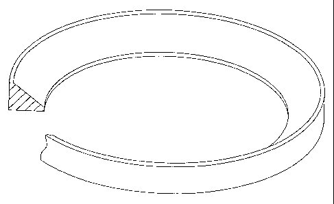
Figure 1 shows a semifinished product in accordance with the state
oftheart,
Figure 2 shows a semifinished product according to the invention of
substantially triangular cross-section,
Figure 3 shows a semifinished product according to the invention
with a concave surface,
Figures 4 and 5 show semifinished products of a first embodiment,
Figures 6 and 7 show semifinished products of a second
embodiment,
Figures 8 and 9 show semifinished products of a third embodiment,
Figures 10 and 11 show a fourth embodiment of the semifinished
products, and
Figure 12 shows a workpiece from which two flanges are produced.
Figure 1 shows a semifinished product as is used in the state of the
art, of a rectangular cross-section, from which the flange is produced.
Figure 2 shows a semifinished product according to the invention of
substantially triangular cross-section, wherein the hypotenuse of the
triangle is straight. Figure 3, instead of a straight hypotenuse, illustrates
an
arc, thus affording a concave surface portion.

CA 02525678 2005-11-14
3
Figure 4 shows a first embodiment, having regard to the state of the
art. The semifinished product is illustrated as being rectangular in this
Figure and a broken line indicates what region of that semifinished product
is not needed in accordance with the invention from the outset.
Figure 5 is a view in cross-section through a corresponding
semifinished product. In this case, in these two, as also in the present
Figures, those regions which have to be removed are always hatched.
The views in Figures 6 and 7 are comparable to those in Figures 4
and 5. The difference is that, in Figures 6 and 7, the inner edge of the
flange ring is no longer rectangular but of a bevelled configuration.
Figures 8 and 9 show a comparable embodiment to that shown in
Figures 4 and 5, but with a concave surface portion instead of a straight
surface.
Figures 10 and 11 show an embodiment with an inclined flange.
Finally Figure 12 again shows a right-angled semifinished product
and illustrates how two flanges can be obtained from such a semifinished
product.

Representative Drawing
A single figure which represents the drawing illustrating the invention.
Administrative Status

2024-08-01:As part of the Next Generation Patents (NGP) transition, the Canadian Patents Database (CPD) now contains a more detailed Event History, which replicates the Event Log of our new back-office solution.

Please note that "Inactive:" events refers to events no longer in use in our new back-office solution.

For a clearer understanding of the status of the application/patent presented on this page, the site Disclaimer , as well as the definitions for Patent , Event History , Maintenance Fee  and Payment History  should be consulted.

Event History

Description Date
Time Limit for Reversal Expired 2023-09-21
Letter Sent 2023-03-20
Letter Sent 2022-09-21
Letter Sent 2022-03-21
Common Representative Appointed 2019-10-30
Inactive: IPC expired 2016-01-01
Grant by Issuance 2010-02-23
Inactive: Cover page published 2010-02-22
Pre-grant 2009-12-04
Inactive: Final fee received 2009-12-04
Notice of Allowance is Issued 2009-11-09
Letter Sent 2009-11-09
Inactive: Approved for allowance (AFA) 2009-10-30
Amendment Received - Voluntary Amendment 2009-04-02
Inactive: S.30(2) Rules - Examiner requisition 2008-10-02
Amendment Received - Voluntary Amendment 2007-12-05
Inactive: S.30(2) Rules - Examiner requisition 2007-06-05
Inactive: Cover page published 2006-01-24
Letter Sent 2006-01-20
Inactive: Acknowledgment of national entry - RFE 2006-01-20
Inactive: Inventor deleted 2006-01-20
Application Received - PCT 2005-12-13
All Requirements for Examination Determined Compliant 2005-11-14
Request for Examination Requirements Determined Compliant 2005-11-14
National Entry Requirements Determined Compliant 2005-11-14
Application Published (Open to Public Inspection) 2004-12-09

Abandonment History

There is no abandonment history.

Maintenance Fee

The last payment was received on 2010-01-21

Note : If the full payment has not been received on or before the date indicated, a further fee may be required which may be one of the following

  • the reinstatement fee;
  • the late payment fee; or
  • additional fee to reverse deemed expiry.

Please refer to the CIPO Patent Fees web page to see all current fee amounts.

Owners on Record

Note: Records showing the ownership history in alphabetical order.

Current Owners on Record
ALOYS WOBBEN
Past Owners on Record
None
Past Owners that do not appear in the "Owners on Record" listing will appear in other documentation within the application.
Documents

To view selected files, please enter reCAPTCHA code :


To view images, click a link in the Document Description column. To download the documents, select one or more checkboxes in the first column and then click the "Download Selected in PDF format (Zip Archive)" or the "Download Selected as Single PDF" button.

List of published and non-published patent-specific documents on the CPD .

If you have any difficulty accessing content, you can call the Client Service Centre at 1-866-997-1936 or send them an e-mail at CIPO Client Service Centre.


Document
Description 
Date
(yyyy-mm-dd) 
Number of pages   Size of Image (KB) 
Description 2005-11-14 3 118
Drawings 2005-11-14 6 94
Representative drawing 2005-11-14 1 9
Claims 2005-11-14 1 24
Abstract 2005-11-14 1 14
Cover Page 2006-01-24 1 38
Description 2007-12-05 3 126
Claims 2007-12-05 1 31
Claims 2009-04-02 1 39
Abstract 2010-02-04 1 14
Cover Page 2010-02-08 1 39
Representative drawing 2010-02-10 1 8
Acknowledgement of Request for Examination 2006-01-20 1 176
Notice of National Entry 2006-01-20 1 201
Commissioner's Notice - Application Found Allowable 2009-11-09 1 163
Commissioner's Notice - Maintenance Fee for a Patent Not Paid 2022-05-02 1 541
Courtesy - Patent Term Deemed Expired 2022-11-02 1 536
Commissioner's Notice - Maintenance Fee for a Patent Not Paid 2023-05-01 1 550
PCT 2005-11-14 7 200
Correspondence 2009-12-04 1 33