Language selection

Search

Patent 2525718 Summary

Third-party information liability

Some of the information on this Web page has been provided by external sources. The Government of Canada is not responsible for the accuracy, reliability or currency of the information supplied by external sources. Users wishing to rely upon this information should consult directly with the source of the information. Content provided by external sources is not subject to official languages, privacy and accessibility requirements.

Claims and Abstract availability

Any discrepancies in the text and image of the Claims and Abstract are due to differing posting times. Text of the Claims and Abstract are posted:

  • At the time the application is open to public inspection;
  • At the time of issue of the patent (grant).
(12) Patent Application: (11) CA 2525718
(54) English Title: A CONNECTION ROD FOR ROCK DRILLING AND A METHOD OF PRODUCING THE SAME
(54) French Title: BARRE DE LIAISON UTILISEE POUR LE FORAGE DE ROCHES, ET SON PROCEDE DE PRODUCTION
Status: Dead
Bibliographic Data
(51) International Patent Classification (IPC):
  • E21B 17/02 (2006.01)
(72) Inventors :
  • NORDFELDT, LEIF (Sweden)
(73) Owners :
  • ATLAS COPCO SECOROC AB (Sweden)
(71) Applicants :
  • ATLAS COPCO SECOROC AB (Sweden)
(74) Agent: KIRBY EADES GALE BAKER
(74) Associate agent:
(45) Issued:
(86) PCT Filing Date: 2004-04-28
(87) Open to Public Inspection: 2004-11-25
Availability of licence: N/A
(25) Language of filing: English

Patent Cooperation Treaty (PCT): Yes
(86) PCT Filing Number: PCT/SE2004/000655
(87) International Publication Number: WO2004/101948
(85) National Entry: 2005-11-14

(30) Application Priority Data:
Application No. Country/Territory Date
0301422-2 Sweden 2003-05-16

Abstracts

English Abstract


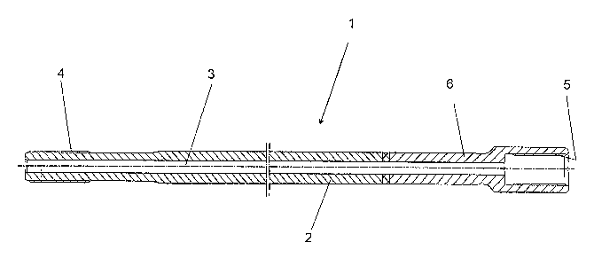
The present invention relates to a connection rod (1) for rock drilling
comprising a first rod part (2) which has an external thread (4) provided at
one end thereof, wherein the end of the rod opposite to said one end includes
an end portion (6) which carries an internal thread (5), wherein the end
portion (6) is joined to the first rod part (2) by friction welding and
wherein the end portion (6) has been heat treated prior to being joined to
said first rod part (2). The invention also relates to a method of producing
such a connection rod.


French Abstract

L'invention concerne une barre de liaison (1) utilisée pour le forage de roches. Cette barre de liaison comprend une première partie de barre (2) pourvue d'un filet externe (4) au niveau d'une extrémité. L'extrémité de la barre située à l'opposé de cette extrémité comprend une partie terminale (6) pourvue d'un filet interne (5). Selon l'invention, cette partie terminale (6) est unie à ladite première partie de barre (2), par soudage par friction, ladite partie terminale (6) étant soumise à un traitement thermique avant d'être unie à la première partie de barre (2). Cette invention se rapporte en outre à un procédé de production de ladite barre de liaison.

Claims

Note: Claims are shown in the official language in which they were submitted.


7

Claims

1. A connection rod (1) for rock drilling comprising a first
rod part (2) which has an external thread (4) provided at one
end thereof, characterised in that the end of
the rod opposite to said one end includes an end portion (6)
which carries an internal thread (5); in that the end portion
(6) is joined to the first rod part (2) by friction welding;
and in that the end portion (6) has been heat treated prior
to being joined to the first rod part (2).

2. A connection rod according to Claim 1, charac-
terised in that the end portion (6) is case hardened.

3. A connection rod according to Claim 1 or 2, charac-
terised in that the end portion (6) includes a shaft
part (7) that extends away from the internal thread (5), said
shaft part being that part of the end portion which has been
joined to the first rod part (2).

4. A connection rod according to any one of the preceding
Claims, characterised in that the first rod part
(2) is comprised of hot rolled rod.

5. A connection rod according to any one of the preceding
Claims, characterised in that the external
thread (4) provided-on said one end is surface hardened.

6. A connection rod according to any one of Claims 1 to 4,
characterised in that the external thread (4)
provided on said one end is tough-hardened.

7. A method of producing a connection rod (1) that comprises
an external thread (4) at one end, characteri-


8

sed by producing and heat treating a separate end portion
(6) that includes an internal thread (5) and joining said
separate end portion (6) to the remainder of the rod by fric-
tion welding.

8. A method according to Claim 7, characterised
by case hardening the separately produced end portion (6)
prior to joining said end portion to the remaining portion
(2) of the rod.

9. A method according to Claim 7, characterised
by providing that part of the end portion (6) lying closest
to the end (9) to be joined to the remaining portion (2) of
the rod with a protective coating or covering and thereafter
case hardening the separately produced end portion (6) prior
to joining said end portion to the remaining portion (2) of
the rod.

10. A method according to Claim 9, characterised
by applying said protective coating to the end surface (10)
that is to be joined to the remaining portion (2) of the rod,
and also to the outer and inner surfaces of the end portion
(6) along a distance of 20 - 50 mm from the end surface (10).

11. A method according to any one of Claims 7 - 10, cha-
racterised by surface hardening the external thread
(4).

12. A method according to any one of Claims 7 - 10, cha-
racterised by tough-hardening the external thread
(4).


Description

Note: Descriptions are shown in the official language in which they were submitted.


CA 02525718 2005-11-14
WO 2004/101948 PCT/SE2004/000655
1
A connection rod for rock drilling and a method of producing the sage.
The present invention relates to a connecting rod of the kind
s in rock drilling operations, both with regard to underground
and surface drilling. The invention also relates to a method
of producing such a rod.
When drilling in rock, connecting rods, or extension pieces,
~o are used between drill bit and shank adapter to enable holes
of desired depths to be drilled. The rods are connected to
one another and to the drill bit and shank adapter by means
of screw joints.
~s The rods are produced in mutually different lengths with
regard to underground drilling, normally lengths of up to
about 3 m, and up to about 6 m with regard to surface drill
ing. A typical rod will have an external thread at one end
and an internal thread at its other end. The rod is straight
2o between the two threaded ends.
In the case of surface drilling, the connecting rods used are
normally in the form of hot-rolled hollow rods which have
been surface hardened at their thread-carrying ends. However,
2s it has been found problematic to achieve satisfactory surface
hardening of the internal thread, owing to the difficulty in
obtaining a uniform profile~depth. In the case of underground
drilling, it has therefor been preferred to have a case hard-
ened internal thread, which makes it necessary to case harden
ao the entire connecting rod and therewith increase production
costs.
Consequently, an object of the present invention is to pro-
vide a novel type of connecting rod with which satisfactory


CA 02525718 2005-11-14
WO 2004/101948 PCT/SE2004/000655
2
hardening of the internally threaded end can be achieved in
particular while still keeping production costs down to a
reasonable level.
The object of the invention is achieved with a connecting rod
which includes a first part having an external thread at one
end and at its opposite end an end portion that carries an
internal thread, wherein said end portion is joined to the
first rod part by friction welding and wherein said end por-
to tion has been heat treated prior to being joined to the first
rod part.
According to one preferred embodiment of the invention end
portion carrying the internal thread is case hardened.
According to a further embodiment of the invention the first
rod part includes an external thread on that end of said rod
part located opposite to the end portion carrying said inter-
nal thread.
As mentioned in the introduction, one object of the present
invention resides in the provision of a method of producing a
connection rod according to the present invention.
This object is achieved by the steps of producing a separate
end portion that includes an internal thread, heat treating
said end portion, and thereafter joini-ng the separately pro-
duced end portion with the remainder of the connection rod by
friction welding.
According to a preferred embodiment of the inventive method
the separately produced end portion is case hardened prior to
being joined to the remainder of the connection rod.


CA 02525718 2005-11-14
WO 2004/101948 PCT/SE2004/000655
3
The invention will now be described with reference to a non-
limiting example thereof and also with reference to the ac-
companying drawings, in which Figure 1 is a schematic longi-
tudinal sectioned view of a connection rod according to the
present invention, and Figure 2 is a schematic side view,
partly in section, of an end portion intended for the inven-
tive connection rod.
The connection rod 1 illustrated in Figure 1 includes a cen-
~o tral section 2 which is formed by a round hot-rolled rod that
has a centrally throughpassing hole 3. The rod 1 includes at
one end an external thread 4 and at its opposite end an end
portion 6 that includes an internal thread 5.
~5 Connecting rods 1 of this design can, in principle, be con-
nected in infinite lengths, by screwing the external thread 4
into an internal thread of another rod.
As will be apparent from Fig. 1, the end portion 6 carrying
2o the internal thread 5 is formed from a material different to
that of the remainder of the rod 1. On the other hand, the
rod end carrying the external thread is comprised of the same
hot-rolled rod as the central section ~ of the connection
rod.
Thus, in accordance with the invention, the end portion 6
carrying the-- internal thread 5 is comprised o-f--~ a material
that is different to the material of said central section 2
and that has been specially heat treated in a way different
so to that of said central section 2 and thereafter joined to
the central section 2 by friction welding.
The heat treatment process to which the end portion 6 is
subjected prior to being joined to the central part 2 of the


CA 02525718 2005-11-14
WO 2004/101948 PCT/SE2004/000655
4
rod is conveniently a case hardening process that will en-
hance the mechanical strength of the internal thread 5 and
the part of the rod joined thereto, i.e. essentially the
whole of the end portion 6. The maximum stresses due to the
s thread connection often occur somewhat inwardly of the actual
thread 5, as seen from the adjacent end of the connection
rod/the end portion. The heat treated end portion therefore
includes a shaft portion 7 that extends somewhat from the
expanded part 8 of the end portion, said expanded part 8
~o including the internal thread 5. Essentially the whole of the
end portion 6, including the shaft portion 7, is heat
treated/hardened in the same way.
In order to optimise material properties in the friction
~s welding process, it is necessary to exclude the end 9 of the
end portion 6 from the case hardening process. The end por-
tion 6 is therefore given a protective coating or covering at
the opposite end 9, at a distance from the end surface 10 in
a direction towards the expanded part 8, prior to the case
2o hardening process. This protective covering or coating is
applied to the actual end surface 10 and to the outside of
the shaft part 7 and also to the central throughpassing hole
3 in said shaft part. The protective coating is applied over
a distance of 20 - 50 mm from the end surface 10 and func-
2s tions to prevent the coated surfaces from taking up carbon
during the carbonisation process, this process resulting in a
higher surface content---of carbon in the end portion 6. It- is
true that the coated opposite end 9 of the end portion will
be hardened to some extent in a following heat treatment
3o process,. but no case hardening will take place at this par-
ticular part of the end portion 6.
By producing the end portion 6 as a separate part and heating
said part per se, there can be produced, in accordance with


CA 02525718 2005-11-14
WO 2004/101948 PCT/SE2004/000655
the invention, an optimised connection rod, where that part
of the rod which is most subjected to stress, i.e. the cen-
tral part 2, and the end of the rod carrying the external
thread 4 are also treated per se. For example, the external
s thread can be heated treated in the manner required, e. g.
surface hardened or tough-hardened, whereas the end portion 6
can be case hardened so as to increase its wear strength.
Respective parts 2 and 6 of the connection rod, each having
~o been heat treated per se, are then joined together by fric-
tion welding. The thus combined connection rod can then be
treated unitarily, for instance shot peening the join area,
to enhance its endurance strength, and then straightened and
coated. The threads at respective ends of the rod can then be
5 treated to protect against corrosion, in a traditional man-
ner.
As will be understood, after the end portion 6 has been
joined to the central part 2 by friction welding it is not
2o necessary to heat treat the final product.
The invention thus provides a connection rod that is optimal
in respect of many different applications and that can be
used in both underground drilling and in surface drilling and
2s where each respective part of the rod has been adequately
heat treated.
As mentioned in the introduction, the invention also relates
to a method of producing a connection rod in accordance with
ao the invention. This method will be apparent from the above
detailed description of the inventive connection rod.
It will be understood that the internal thread 5 and the
external thread 4 can be heat treated in accordance with


CA 02525718 2005-11-14
WO 2004/101948 PCT/SE2004/000655
6
other appropriate methods than those described above. Despite
the possibility of heat treating the various parts of the rod
with different methods, an important feature of the invention
resides in the ability to achieve such treatment without
s needing to heat treat the whole of the rod in one and the
same way.

Representative Drawing
A single figure which represents the drawing illustrating the invention.
Administrative Status

For a clearer understanding of the status of the application/patent presented on this page, the site Disclaimer , as well as the definitions for Patent , Administrative Status , Maintenance Fee  and Payment History  should be consulted.

Administrative Status

Title Date
Forecasted Issue Date Unavailable
(86) PCT Filing Date 2004-04-28
(87) PCT Publication Date 2004-11-25
(85) National Entry 2005-11-14
Dead Application 2010-04-28

Abandonment History

Abandonment Date Reason Reinstatement Date
2009-04-28 FAILURE TO REQUEST EXAMINATION
2009-04-28 FAILURE TO PAY APPLICATION MAINTENANCE FEE

Payment History

Fee Type Anniversary Year Due Date Amount Paid Paid Date
Registration of a document - section 124 $100.00 2005-11-14
Application Fee $400.00 2005-11-14
Maintenance Fee - Application - New Act 2 2006-04-28 $100.00 2006-03-29
Maintenance Fee - Application - New Act 3 2007-04-30 $100.00 2007-04-04
Maintenance Fee - Application - New Act 4 2008-04-28 $100.00 2008-03-12
Owners on Record

Note: Records showing the ownership history in alphabetical order.

Current Owners on Record
ATLAS COPCO SECOROC AB
Past Owners on Record
NORDFELDT, LEIF
Past Owners that do not appear in the "Owners on Record" listing will appear in other documentation within the application.
Documents

To view selected files, please enter reCAPTCHA code :


To view images, click a link in the Document Description column. To download the documents, select one or more checkboxes in the first column and then click the "Download Selected in PDF format (Zip Archive)" or the "Download Selected as Single PDF" button.

List of published and non-published patent-specific documents on the CPD .

If you have any difficulty accessing content, you can call the Client Service Centre at 1-866-997-1936 or send them an e-mail at CIPO Client Service Centre.


Document
Description 
Date
(yyyy-mm-dd) 
Number of pages   Size of Image (KB) 
Abstract 2005-11-14 1 59
Claims 2005-11-14 2 72
Drawings 2005-11-14 2 27
Description 2005-11-14 6 228
Representative Drawing 2005-11-14 1 12
Cover Page 2006-01-26 1 39
Claims 2005-11-15 3 90
PCT 2005-11-14 4 124
Assignment 2005-11-14 4 96
Correspondence 2006-01-24 1 27
Assignment 2006-02-27 2 67
PCT 2005-11-15 6 234