Language selection

Search

Patent 2526092 Summary

Third-party information liability

Some of the information on this Web page has been provided by external sources. The Government of Canada is not responsible for the accuracy, reliability or currency of the information supplied by external sources. Users wishing to rely upon this information should consult directly with the source of the information. Content provided by external sources is not subject to official languages, privacy and accessibility requirements.

Claims and Abstract availability

Any discrepancies in the text and image of the Claims and Abstract are due to differing posting times. Text of the Claims and Abstract are posted:

  • At the time the application is open to public inspection;
  • At the time of issue of the patent (grant).
(12) Patent: (11) CA 2526092
(54) English Title: DEVICE FOR TRANSVERSALLY CUTTING A ROLLED STRIP
(54) French Title: DISPOSITIF DE CISAILLAGE A COUPE TRANSVERSALE D'UNE BANDE DE LAMINAGE
Status: Granted and Issued
Bibliographic Data
(51) International Patent Classification (IPC):
  • B23D 25/12 (2006.01)
  • B21D 43/28 (2006.01)
  • B23D 33/02 (2006.01)
(72) Inventors :
  • BAEUMER, KLAUS (Germany)
  • MERZ, JUERGEN (Germany)
(73) Owners :
  • SMS SIEMAG AKTIENGESELLSCHAFT
(71) Applicants :
  • SMS SIEMAG AKTIENGESELLSCHAFT (Germany)
(74) Agent: RICHES, MCKENZIE & HERBERT LLP
(74) Associate agent:
(45) Issued: 2010-09-07
(86) PCT Filing Date: 2004-05-25
(87) Open to Public Inspection: 2004-12-23
Examination requested: 2009-02-27
Availability of licence: N/A
Dedicated to the Public: N/A
(25) Language of filing: English

Patent Cooperation Treaty (PCT): Yes
(86) PCT Filing Number: PCT/EP2004/005582
(87) International Publication Number: WO 2004110688
(85) National Entry: 2005-11-16

(30) Application Priority Data:
Application No. Country/Territory Date
103 26 383.7 (Germany) 2003-06-12

Abstracts

English Abstract


The invention relates to a device for transversally cutting a rolled strip
using shears, especially drum shears. According to the invention, a gap
between the end of the roller table upstream of the shears and the beginning
of the roller table downstream of the shears, where there is no support for
the rolled strip, is reduced by a pivotable roller table part supporting the
rolled strip as it passes through, and a mobile guiding table is arranged
between said pivotable roller table part and the beginning of the rear roller
table.


French Abstract

L'invention concerne un dispositif de cisaillage à coupe transversale d'une bande de laminage à l'aide d'une cisaille, notamment d'un tambour cisaille. Un vide situé entre la fin du train de rouleaux en amont de la cisaille et le début du train de rouleaux en aval de la cisaille, la bande de laminage n'ayant aucun support, est réduit par une partie rotative du train de rouleaux supportant la bande de laminage lors de son défilement. Un plateau de guidage mobile est placé entre une partie rotative de train de rouleaux et le début du train de rouleaux arrière.

Claims

Note: Claims are shown in the official language in which they were submitted.

CLAIMS
1. Device for cutting rolled strip to length with a shear,
especially a rotary shear, in which a gap between the end of the
roller table upstream of the shear and the beginning of the
roller table downstream of the shear, where the rolled strip is
unsupported, is reduced by a swiveling roller table part that
supports the rolled strip as it passes through, characterized by
the fact that a movable guide table (18) is arranged between a
swiveling roller table part (17) and the beginning of the rear
roller table (4).
2. Device in accordance with Claim 1, characterized by the
fact that a movable guide table (19) is arranged between the end
of the front roller table (3) and the swiveling roller table
part (17).
3. Device in accordance with Claim 1 or Claim 2,
characterized by the fact that the outer surface of the
swiveling roller table part (17) is engaged with the outer
surface of the movable guide table (18, 19).
4. Device in accordance with any of Claims 1 to 3,
characterized by the fact that the upper drum (6) and the lower
drum (8) have flattened surfaces (15, 15', 16, 16') on their
outer periphery.
8

5. Device in accordance with any of Claims 1 to 4,
characterized by the fact that a movable deflector (13) is
arranged upstream of the upper drum (6).
6. Device in accordance with any of Claims 1 to 5,
characterized by the fact that a stationary or movable deflector
(14) is arranged downstream of the upper drum (6).
9

Description

Note: Descriptions are shown in the official language in which they were submitted.


CA 02526092 2005-11-16
TRANSLATION (HM-674PCT):
WO 2004/110,688 Al
PCT/EP2004/005,582
DEVICE FOR TRANSVERSALLY CUTTING A ROLLED STRIP
The invention concerns a device for cutting rolled strip to
length with a shear, especially a rotary shear, in which a gap
between the end of the roller table upstream of the shear and
the beginning of the roller table downstream of the shear, where
the rolled strip is unsupported, is reduced by a swiveling
roller table part that supports the rolled strip as it passes
through.
Shears for cutting rolled strip to length in a hot rolling
wide strip mill, in a cold-rolling tandem mill, and in hot
rolling and cold rolling mills are well known. The use of crank
shears and rotary shears is preferred for this purpose. Designs
of rotary shears are described, for example, in DE 199 53 906 Al
and in DE 100 Ol 928 Al.
DE 12 70 368 describes a crank shear for rolled steel in
which a conveying roller table has a gap in the area of the
cutter circle. A rotating conveying segment that has
approximately the width of the cutter and is provided with an
1

CA 02526092 2005-11-16
approximately semicircularly curved outer surface closes the gap
in the conveying roller table when the segment is in its upper
position.
A disadvantage of the known designs of a device of this
type for cutting rolled strip to length is that, although the
distance of the support points / support lines of the rolled
strip upstream and downstream of the shear is reduced by a
conveying segment that can be rotated in, the rolled strip
experiences a deviation from the rolling or conveying direction,
depending on the thickness, the surface tension, etc. Due to
the greater distances between the support points or lines, the
strip flow is disturbed in the device for cutting rolled strip
to length. The leading end of the strip reacts very sensitively
to these greater distances. The rolled strip can become
oriented towards the top or the bottom in this area and can
become jammed, e.g., between the conveying segment and the
roller table. The equipment has to be shut down. The thinner
the rolled strip is, the greater the danger that this will
occur.
Therefore, the objective of the invention is to create a
device for cutting rolled strip to length which avoids the
aforesaid disadvantages.
2

CA 02526092 2005-11-16
In accordance with the invention, this objective is
achieved by arranging a movable guide table between a swiveling
roller table part and the beginning of the downstream roller
table. This movable guide table reduces the distance without
support points / support lines for the rolled strip in such a
way that deviation of the rolled strip is not possible.
It is advantageous if an additional, movable guide table
that is interlocked with the swiveling roller table part is
arranged between the end of the upstream roller table and the
swiveling roller table. The gap in the roller table is then
completely closed.
In an advantageous refinement of the invention, the upper
drum and the lower drum have flattened surfaces on their outer
periphery. This creates a larger opening for the passage of the
rolled strip, and during the threading of the rolled strip, the
drums, especially the upper drum, do not present obstacles on
which the rolled strip is stopped.
It is also advantageous for a movable deflector to be
arranged in front of the upper drum. This provides an entry
funnel for the rolled strip, thereby preventing upward deviation
of the rolled strip.
3

CA 02526092 2005-11-16
Additional refinements of the device of the invention are
specified in the dependent claims.
A specific embodiment of the invention is described in
greater detail below with reference to the highly schematic
drawings.
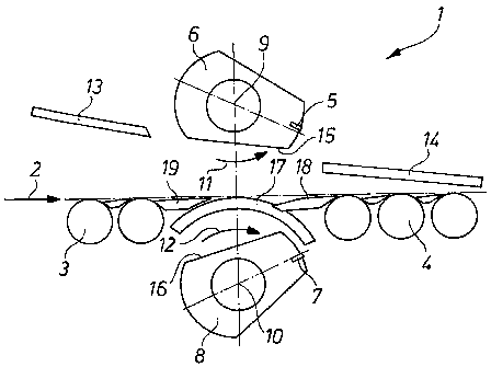
-- Figure 1 shows a device for cutting rolled strip to
length in the position in which the beginning of the strip is
threaded in.
-- Figure 2 shows a device according to Figure 1 in the
cutting position.
Figure 1 shows a device 1 for cutting rolled strip 2 to
length with a front roller table 3 and a rear roller table 9.
The rolled strip 2 is cut by an upper cutter 5, which is mounted
on an upper drum 6, and a lower cutter 7, which is mounted on a
lower drum 8. The drums 6, 8 rotate in opposite directions
about an upper axis of rotation 9 and a lower axis of rotation
10. The direction of rotation is indicated by arrows 11, 12.
A movable deflector 13 is located above the front roller
table 3. A stationary or movable deflector 14 is located above
the rear roller table 4.
The drums 6, 8 are rotated in such a way during the
threading of the strip that the flattened surfaces 15, 15', 16,
4

CA 02526092 2005-11-16
16', especially the flattened surface 15 on the upper drum 6,
are oriented, together with the movable deflector 13, so as to
form an entry funnel.
To ensure that the rolled strip 2, which is supported on
the front roller table 3, arrives safely on the rear roller
table 4, a swiveling roller table part 17 is rotated into a gap.
In this rotation, the swiveling roller table part 17 moves
around the lower drum 8. To close the gap completely, movable
guide tables 18, 19 are arranged between the swiveling roller
table part 17 and the front roller table 3 and between the
swiveling roller table part 17 and the rear roller table 4. To
close the gap completely, the swiveling roller table part 17 and
the movable guide table 18, 19 are interlocked.
Figure 2 shows the rolled strip 2 and the drums 6, 8 with
the cutters 5, 7. The cutters 5, 7 are now positioned in a
cutting position. To this end, the upper drum 6 with the upper
cutter 5 and the lower drum 8 with the lower cutter 7 are
rotated in opposite directions about the upper axis of rotation
9 and the lower axis of rotation 10, respectively. To
accomplish this, the swiveling roller table part 17 was rotated
out of the gap in the roller table.

CA 02526092 2005-11-16
To prevent damage to the swiveling roller table 17 by, for
example, falling residual pieces of the rolled strip 2, the
swiveling roller table part 17 is rotated in such a way that it
is covered by the lower drum 8.
In addition, the movable guide tables 18, 19 can avoid the
circular arc through which the lower cutter 8 moves. This is
accomplished, for example, by a linear lateral movement or a
rotational movement.
6

CA 02526092 2005-11-16
LIST OF REFERENCE NUMBERS
1 cut-to-length device
2 rolled strip
3 front roller table
4 rear roller table
upper cutter
6 upper drum
7 lower cutter
8 lower drum
9 upper axis of rotation
lower axis of rotation
11 direction of rotation of the upper drum
12 direction of rotation of the lower drum
13 movable deflector
14 stationary deflector
15, 15' flattened surface of the upper drum
16, 16' flattened surface of the lower drum
17 movable roller table part
18 movable guide table
19 movable guide table
7

Representative Drawing
A single figure which represents the drawing illustrating the invention.
Administrative Status

2024-08-01:As part of the Next Generation Patents (NGP) transition, the Canadian Patents Database (CPD) now contains a more detailed Event History, which replicates the Event Log of our new back-office solution.

Please note that "Inactive:" events refers to events no longer in use in our new back-office solution.

For a clearer understanding of the status of the application/patent presented on this page, the site Disclaimer , as well as the definitions for Patent , Event History , Maintenance Fee  and Payment History  should be consulted.

Event History

Description Date
Common Representative Appointed 2019-10-30
Grant by Issuance 2010-09-07
Inactive: Cover page published 2010-09-06
Inactive: Final fee received 2010-06-18
Pre-grant 2010-06-18
Notice of Allowance is Issued 2010-06-01
Letter Sent 2010-06-01
Notice of Allowance is Issued 2010-06-01
Inactive: Approved for allowance (AFA) 2010-05-17
Letter Sent 2009-10-26
Letter Sent 2009-04-02
Amendment Received - Voluntary Amendment 2009-03-03
Request for Examination Requirements Determined Compliant 2009-02-27
All Requirements for Examination Determined Compliant 2009-02-27
Request for Examination Received 2009-02-27
Letter Sent 2006-03-21
Inactive: Single transfer 2006-02-16
Inactive: Cover page published 2006-01-25
Inactive: Courtesy letter - Evidence 2006-01-24
Inactive: Notice - National entry - No RFE 2006-01-23
Application Received - PCT 2005-12-19
National Entry Requirements Determined Compliant 2005-11-16
Application Published (Open to Public Inspection) 2004-12-23

Abandonment History

There is no abandonment history.

Maintenance Fee

The last payment was received on 2010-04-29

Note : If the full payment has not been received on or before the date indicated, a further fee may be required which may be one of the following

  • the reinstatement fee;
  • the late payment fee; or
  • additional fee to reverse deemed expiry.

Please refer to the CIPO Patent Fees web page to see all current fee amounts.

Owners on Record

Note: Records showing the ownership history in alphabetical order.

Current Owners on Record
SMS SIEMAG AKTIENGESELLSCHAFT
Past Owners on Record
JUERGEN MERZ
KLAUS BAEUMER
Past Owners that do not appear in the "Owners on Record" listing will appear in other documentation within the application.
Documents

To view selected files, please enter reCAPTCHA code :


To view images, click a link in the Document Description column. To download the documents, select one or more checkboxes in the first column and then click the "Download Selected in PDF format (Zip Archive)" or the "Download Selected as Single PDF" button.

List of published and non-published patent-specific documents on the CPD .

If you have any difficulty accessing content, you can call the Client Service Centre at 1-866-997-1936 or send them an e-mail at CIPO Client Service Centre.


Document
Description 
Date
(yyyy-mm-dd) 
Number of pages   Size of Image (KB) 
Abstract 2005-11-16 2 81
Description 2005-11-16 7 166
Claims 2005-11-16 2 36
Drawings 2005-11-16 1 17
Representative drawing 2006-01-25 1 10
Cover Page 2006-01-25 1 41
Cover Page 2010-08-17 2 45
Notice of National Entry 2006-01-23 1 192
Courtesy - Certificate of registration (related document(s)) 2006-03-21 1 105
Reminder - Request for Examination 2009-01-27 1 117
Acknowledgement of Request for Examination 2009-04-02 1 176
Commissioner's Notice - Application Found Allowable 2010-06-01 1 167
PCT 2005-11-16 2 79
Correspondence 2006-01-23 1 27
Fees 2007-05-10 1 44
Correspondence 2010-06-18 1 50