Note: Descriptions are shown in the official language in which they were submitted.
CA 02526098 2005-11-16
1
Title of the Invention:
MULTI-LAYER STRUCTURE FOR PACKAGING
Technical Field:
The present invention relates to a multi-layer
structure for packaging having a functional resin
layer such as a gas barrier resin layer or the like
layer as an intermediate layer.
Background Art:
Polyester resins as represented by a polyethylene
terephthalate have excellent properties such as
moldability, transparency, mechanical strength and
resistance against chemicals, as well as excellent gas
barrier property such as against oxygen and can,
hence, be used as packaging materials such as films,
sheets and bottles in a variety of fields.
In order to enhance the gas barrier property of
the above packaging material, further, there has been
proposed a packaging material having a functional
resin layer comprising a gas barrier material such as
a saponified product of an ethylene/vinyl acetate
copolymer or a polyamide as an intermediate layer
between the inner layer and the outer layer. The
above packaging material, however, is accompanied by a
problem of interlayer peeling due to low adhesion
strength between a functional resin constituting an
intermediate layer and a resin (e.g., a polyester
resin) constituting the inner and outer layers.
In the multi-layer structure for packaging having
the functional resin layer as the intermediate layer
between the inner layer and the outer layer,
therefore, it is a generally accepted practice to
provide adhesive layers among the functional resin
layer and the inner and outer layers to increase the
adhering strength and to suppress the interlayer
CA 02526098 2005-11-16
2
peeling.
There has been known, for example, a laminate
having graft-modified ethylene/a-olefin random
copolymer layers (adhesive layers) provided among the
polyester resin layers (inner and outer layers) and a
layer of a saponified product of an olefin/vinyl
acetate copolymer (functional resin layer)(Japanese
Unexamined Patent Publication (Kokai) No. 62-158043).
There has further been proposed a multi-layer
container having a mixed resin layer obtained by
mixing a gas barrier resin into a polyester resin, the
amounts of the polyester resin particles and of the
gas barrier resin particles of not larger than 10 pm
being not larger than 10%. According to the above
multi-layer container, the adhesion among the layers
can be improved without decreasing the transparency
(Japanese Examined Patent Publication (Kokoku) No. 8-
25220).
Disclosure of the Invention:
When adhesive layers are provided among the
functional resin layer and the inner and outer layers
as represented by the laminate of the above Japanese
Unexamined Patent Publication (Kokai) No. 62-158043,
however, an extruder is necessary for forming the
adhesive layer resulting in an increase in the cost of
production.
When the resins exist in a coarsely mixed state
in the mixed layer of the gas barrier resin and the
polyester resin as taught in the above Japanese
Examined Patent Publication (Kokoku) No. 8-25220,
further, the gas barrier property possessed by the gas
barrier resin is not effectively exhibited and,
besides, the mixed layer exhibits deteriorated
mechanical strength.
It is therefore an object of the present
CA 02526098 2009-06-09
. . =
67616-262
3
invention to provide a multi-layer structure for
packaging featuring improved adhesion among the layers
without providing any particular adhesive layers among
the intermediate layer having a function such as gas
barrier property and the inner and outer layers.
It is another object of the present invention to
provide a multi-layer structure for packaging capable
of efficiently exhibiting the function such as gas
barrier property and featuring excellent transparency.
According to the present invention, there is
provided a multi-layer structure for packaging formed
by at least an inner layer, an outer layer and an
intermediate layer, the intermediate layer having an
islands-in-a-sea structure comprising a resin A
constituting sea po.rtions.and a.functional resin B
constituting island portions, the sea portions
occupying not more than 80% of the area of the
intermediate layer in cross section, and the inner
layer and the outer layer being resins having
adhesiveness to the resin A.
In the present invention, it is desired that:
1. the island portions have an average domain
diameter r of smaller than 3.5 pm and a dispersion
parameter Q of larger than 0.68, the average domain
diameter r being expressed by the following formula
.(1) ~
n
r = Eri/n --- (1)
.1
and the dispersion parameter Q being expressed by the
following formula (2),
n
Q = EQ;. , 1nQi/ln (1/n) --- (2)
1
wherein r;, is a domain diameter, n is a number of
CA 02526098 2005-11-16
4
domains, and when a short diameter of domain is ai
and a long diameter of domain is bi, the domain
diameter ri is ri =(ai + bi) /2, and
n
Qi = n(ri/2) 2/ (Fn (ri/2) 2)
1
2. the resin A is a polyester;
3. the functional resin B is a gas barrier resin;
4. the intermediate layer has oxygen-absorbing
ability;
5. the functional resin B contains an oxidizing
organic component and a catalyst;
6. the oxidizing organic component is not existing
in the sea portions comprising the resin A; and
7. the functional resin B has a melt viscosity
relatively higher than that of the resin A.
In the present invention, it is important that
the intermediate layer comprises the resin A and the
functional resin B having adhesiveness to the resins
forming the inner and outer layers, and has an
islands-in-a-sea structure in which the resin A is
serving as the sea portions and the functional resin B
is serving as the island portions, and the sea
portions are occupying not more than 80% of the area
of the intermediate layer in any cross section
thereof. This enables the functional resin B to
exhibit its properties to a sufficient degree and,
hence, to maintain excellent interlayer adhesion.
That is, in the multi-layer structure for
packaging of the invention, the resins forming the
inner and outer layers and the resin A having
adhesiveness are existing as sea portions in the
intermediate layer. Therefore, the intermediate layer
exhibits excellent interlayer adhesion to the inner
and outer layers. In the intermediate layer, further,
CA 02526098 2005-11-16
the functional resin B is being dispersed as island
portions and, besides, the sea portions are limited
not to occupy more than 80% of the area. Therefore,
the in.termediate layer exhibits excellent gas barrier
5 property inherent in the functional resin B.
For example, even when there is used the resin A
having adhesiveness to the resins forming the inner
and outer layers, the interlayer adhesion decreases
among the inner layer, outer layer and intermediate
layer if the resin A is not existing as the sea
portions. Further, if the sea portions become greater
than 80% of the area in the intermediate layer formed
by the resin A, features such as gas barrier property
possessed by the functional resin B are not exhibited
to a sufficient degree.
In the present invention, further, the average
domain diameter (of the undrawn portions) expressed by
the above formula (1) is smaller than 3.5 pm in the
island portions comprising the functional resin B, and
the dispersion parameter Q expressed by the above
formula (2) is larger than 0.68, i.e., the island
portions comprising the functional resin B have
relatively small particle sizes and are existing in
the sea portions in a narrow grain size distribution.
Therefore, the function such as gas barrier property
inherent in the functional resin B is exhibited to a
sufficient degree and, besides, excellent transparency
is obtained. As for the dispersion parameter Q, the
domain diameters of the island portions become a
monodispersion when Q = 1, i.e., the sizes of the
islands are uniformed as Q approaches 1.
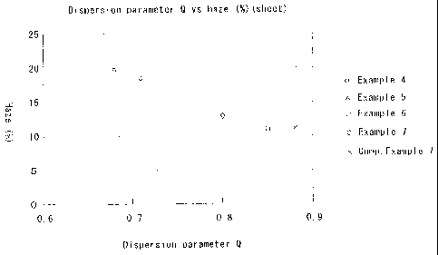
Fig. 1 is a diagram illustrating a relationship
between the dispersion parameter Q of a multi-layer
structure sheet of the present invention and the haze
(%) of the sheet of when the multi-layer structure
CA 02526098 2006-05-10
67616-262
6
sheet is drawn into 3 times x 3 times in the longitudinal
and transverse directions. As will be obvious from Fig. 1,
the haze decreases and the transparency increases as the
dispersion parameter Q representing the grain size
distribution of the island portions approaches 1. In the
multi-layer structure for packaging for which transparency
is required and, particularly, in the case of a bottle, in
general, it is desired that the haze is not larger than 20%.
In the multi-layer structure of the present invention as
will be obvious from Fig. 2 which shows a relationship
between the dispersion parameter Q and the haze of a multi-
layer bottle, the haze becomes smaller than 20% when the
dispersion parameter Q is near 0.68, from which it is
obvious that a satisfactory transparency is maintained.
As will be described later, further, it is desired
that the island portions have an average domain diameter of
not larger than 3.5 m to fully draw the characteristics of
the functional resin B constituting the island portions and
to enhance the mechanical strength thereof. As the island
portions have an average domain diameter of smaller than 3.5
m and, preferably, 3 m and exist in a narrow particle size
distribution, it is allowed to fulfill all of transparency,
functions such as gas barrier property and mechanical
strength.
According to the invention, further, when the
functional resin B contains an oxidizing organic component
and a catalyst, it is particularly desired that the
oxidizing organic component exists in the island portions
only of the functional resin B but does not exist in the sea
portions that comprise the resin A from the standpoint of
improving the transparency.
CA 02526098 2006-05-10
67616-262
6a
Fig. 3 is a schematic diagram of an electron
microphotograph of a sheet obtained by injection-
CA 02526098 2005-11-16
7
molding a dry-blend of a polyester resin as a resin A
and an oxygen-absorbing resin composition obtained by
biaxially kneading a polyamide resin, an oxidizing
organic component and a transition metal catalyst, as
a functional resin B at a weight ratio of 50:50. Fig.
4 is a schematic diagram of an electron
microphotograph of a sheet obtained by injection-
molding a biaxially kneaded blend of four components
which are a polyester resin (resin A), a polyamide
resin, an oxidizing organic component and a transition
metal catalyst constituting an oxygen-absorbing resin
composition (functional resin B).
Figs. 3 and 4 are both forming islands-in-a-sea
structures comprising island portions (b) of the
oxygen-absorbing gas barrier resin composition in the
sea portion (a) of the polyester resin. In Fig. 3,
however, the oxidizing organic component (c) is
existing in only the island portions comprising the
polyamide resin while in Fig. 4, the oxidizing organic
component is existing not only in the island portions
but also in the polyester resin of the sea portion.
Fig. 5 is a diagram illustrating the hazes of the
extrusion-molded sheets of Figs. 3 and 4 that are
drawn into 3 times x 3 times in the longitudinal and
transverse directions. As will be obvious from Fig.
5, the sheet (Fig. 3) containing the oxidizing organic
component in the island portions only has a haze of
about 12% featuring excellent transparency. On the
other hand, the sheet containing the oxidizing organic
component not only in the island portions but also in
the sea portion of Fig. 4, has a haze of larger than
60% exhibiting very inferior transparency. The haze
increases as described above depending upon the state
of the oxidizing organic component probably because
the oxidizing organic component used in the present
CA 02526098 2006-05-10
67616-262
8
invention is existing not only in the island portions but
also in the sea portion resulting in an increase in the
scattering points of light. Besides, the compatibility is
not good between the oxidizing organic component and the
polyester resin which constitutes the sea portion.
Therefore, the oxidizing organic component in the sea
portion is existing in the form of particles that scatter
light causing an increase in the haze.
Brief Description of the Drawings:
Fig. 1 is a diagram illustrating a relationship
between the dispersion parameter Q and the haze of a multi-
layer structure sheet;
Fig. 2 is a diagram illustrating a relationship
between the dispersion parameter Q and the haze of a multi-
layer structure sheet;
Fig. 3 is a schematic diagram of an electron
microphotograph of a sheet comprising a dry-blend of a
polyester resin (resin A) and a functional resin B that
includes an oxidizing organic component, a transition metal
catalyst and a polyamide resin;
Fig. 4 is a schematic diagram of an electron
microphotograph of a sheet comprising a blend of four
components which are a polyester resin, a polyamide resin,
an oxidizing organic component and a transition metal
catalyst;
Fig. 5 is a diagram illustrating the hazes of the
sheets of Figs. 3 and 4 that are drawn into 3 times x 3
times in the longitudinal and transverse directions; and
CA 02526098 2006-05-10
67616-262
8a
Fig. 6 is a view illustrating a representative
layer constitution of a multi-layer structure for packaging
of the present invention.
Best Mode for Carrying Out the Invention:
Fig. 6 is a view illustrating a representative
layer constitution of a multi-layer structure for packaging
of the present invention. As will be
CA 02526098 2005-11-16
9
obvious from Fig. 6, the multi-layer structure
includes three layers, i.e., an inner layer la, an
outer layer lb, and an intermediate layer 2 formed
therebetween. No adhesive layer is existing among the
inner layer la, outer layer lb and intermediate layer
2 for adhering them together.
(Inner layer la and outer layer 1b)
As the resins for constituting the inner and
outer layers la and lb according to the present
invention, there can be used any resin that has
heretofore been used for the containers such as cups
and bottles without limitation. Generally, however,
there is used an olefin resin or a polyester resin
from the standpoint of moldability and transparency.
As the olefin resin, there can be exemplified a
polyethylene such as low-density polyethylene (LDPE),
middle-density polyethylene (MDPE), high-density
polyethylene (HDPE), linear low-density polyethylene
(LLPDE) or linear very low-density polyethylene
(LVLDPE), or polypropylene, ethylene/propylene
copolymer, polybutene-1, ethylene/butene-1 copolymer,
propylene/butene-1 copolymer,
ethylene/propylene/butene-1 copolymer, ethylene/vinyl
acetate copolymer, or ionically crosslinked olefin
copolymer (ionomer).
In the present invention, the polyester resin is
most desirably used. In particular, there is used the
one that can be biaxially draw-blow-molded and
crystallized, such as a thermoplastic polyester like
polyethylene terephthalate, polybutylene terephthalate
or polyethylene naphthalate, or a blend of these
polyesters and a polycarbonate or an arylate resin.
In the present invention, it is desired that most
(generally, not less than 80 mol%) of the ester
recurring units is an ethylene terephthalate unit of a
CA 02526098 2005-11-16
polyethylene terephthalate (PET) polyester having a
glass transition point (Tg) of 50 to 90 C and,
particularly, 55 to 80 C, and a melting point (Tm) of
200 to 275 C and, particularly, 220 to 270 C.
5 As the PET polyester, the homopolyethylene
terephthalate can be most desirably used but still
there can be preferably used a copolymerized polyester
having an ethylene terephthalate unit content lying in
the above range.
10 In the copolymerized polyester, examples of the
dibasic acid other than the terephthalic acid include
aromatic dicarboxylic acids such as isophthalic acid,
phthalic acid and naphthalinedicarboxylic acid;
alicyclic dicarboxylic acids such as
cyclohexanedicarboxylic acid; and aliphatic
dicarboxylic acids such as succinic acid, adipic acid,
sebacic acid, and dodecanedioic acid, which may be
used in one kind or in a combination of two or more
kinds. As the diol components other than the ethylene
glycol, there can be exemplified propylene glycol,
1,4-butanediol, diethylene glycol, 1,6-hexylene
glycol, cyclohexane dimethanol, and ethylene oxide
adduct of bisphenol A.
The resin that constitutes the inner and outer
layers la and lb must have a molecular weight which is
at least large enough for forming a film. When the
resin is, for example, the above-mentioned polyester,
it should have an intrinsic viscosity (I.V) of 0.6 to
1.40 dl/g and, particularly, 0.63 to 1.30 dl/g.
The inner layer la and the outer layer lb need
not necessarily be made of the same kind of resin so
far as they exhibit adhesiveness to the resin A that
constitutes the sea portion in the intermediate layer.
For instance, the outer layer lb may be made of a
polyester and the inner layer la may be made of a
CA 02526098 2005-11-16
11
functional resin such as a gas-barrier resin that will
be described later.
As required, further, the inner and outer layers
la and lb may be blended with a lubricant, a reforming
agent, a pigment, an ultraviolet-ray absorbing agent,
etc.
(Intermediate layer 2)
I As will be obvious from Fig. 6, the intermediate
layer 2 has an islands-in-a-sea structure in which the
resin A serves as the sea portion (or matrix) and the
functional resin B serves as island portions.
[Functional resin B]
As the functional resin B, there can be used, for
example, a gas-barrier resin. A representative
example of the gas-barrier resin is an ethylene/vinyl
alcohol copolymer, such as a saponified product of a
copolymer obtained by saponifying an ethylene/vinyl
acetate copolymer having an ethylene content of 20 to
60 molo and, particularly, 25 to 50 mol%, so that the
degree of saponification is not lower than 96% and,
particularly, not lower than 99 mol%. The
ethylene/vinyl alcohol copolymer (saponified product
of ethylene/vinyl acetate copolymer) must have a
molecular weight large enough for forming a film and,
desirably, should have an intrinsic viscosity of not
smaller than 0.01 dl/g and, particularly, not smaller
than 0.05 dl/g as measured in a mixed solvent of
phenol and water at a weight ratio of 85/15 at 30 C.
Examples of the gas-barrier resin other than the
ethylene/vinyl alcohol copolymer include polyamides
such as nylon 6, nylon 6,6, nylon 6/6,6 copolymer,
poly(m-xylylene adipamide) (MXD6), nylon 6,10, nylon
11, nylon 12 and nylon 13. Among these polyamides, it
is preferred to use the one that has the amide groups
in a number of 5 to 50 and, particularly, 6 to 20 per
CA 02526098 2006-05-10
67616-262
12
100 carbon atoms.
These polyamides, too, must have molecular
weights large enough for forming a film and must,
desirably, have relative viscosities of not smaller
than 1.1 and, particularly, not smaller than 1.5 as
measured in a concentrated sulfuric acid
(concentration of 1.0 g/dl) at 30 C.
Among them, a poly(m-xylylene adipamide) having
terminal amino groups in an amount of smaller than 40
eq/106 g has an excellent oxidizing function, and can
be used as the functional resin B together with a
transition metal catalyst that will be described
later, i.e., can be used as the intermediate layer so
as to exhibit an oxygen-absorbing function so as to
absorb and trap oxygen. It is further allowable to
blend an oxidizing organic component and a transition
metal catalyst (oxidizing catalyst) in the gas
barrier layer to impart oxygen-absorbing property
to the gas-barrier resin used as the functional resin
B, i.e., to impart oxygen-absorbing ability to the
intermediate layer. That is, by oxidizing the
oxidizing organic component, oxygen is absorbed and
trapped, and the gas-barrier resin exhibits an
enhanced oxygen barrier function. The transition
metal catalyst is blended to promote the oxidation of
the oxidizing polymer. These oxidizing organic
component and the transition metal catalyst, too, are
dispersed together with the functional resin B like
islands.
In this case, oxygen is absorbed and trapped by
the oxidizing organic component and the transition
metal catalyst preventing the gas-barrier resin from
being deteriorated by oxidation, preventing interlayer
peeling and preventing a drop in the gas barrier
property. As a preferred example, the functional
CA 02526098 2005-11-16
13
resin B includes a metaxylylenediadipamide having
terminal amino groups in an amount of not smaller than
40 eq/106 g, an oxidizing organic component and a
transition metal catalyst.
As the oxidizing organic component with which the
gas barrier resin is blended, there can be exemplified
a polymer containing an ethylenically unsaturated
group. Namely, this polymer has a carbon-carbon
double bond which is easily oxidized with oxygen to
thereby absorb and trap oxygen.
The polymer having the ethylenically unsaturated
group is derived from a monomer of polyene. Though
not limited thereto only, preferred examples of the
polyene include conjugated dienes such as butadiene
and isoprene; chain non-conjugated dienes such as 1,4-
hexadiene, 3-methyl-1,4-hexadiene, 4-methyl-1,4-
hexadiene, 5-methyl-1,4-hexadiene, 4,5-dimethyl-1,4-
hexadiene, and 7-methyl-1,6-octadiene; cyclic non-
conjugated dienes such as methyltetrahydroindene, 5-
ethylidene-2-norbornene, 5-methylene-2-norbornene, 5-
isopropylidene-2-norbornene, 5-vinylidene-2-
norbornene, 6-chloromethyl-5-isopropenyl-2-norbornene,
and dicyclopentadiene; and trienes such as 2,3-
diisopropylidene-5-norbornene, 2-ethylidene-3-
isopropylidene-5-norbornene, 2-propenyl-2,2-
norbornadiene, and chloroprenes.
Namely, it is allowable to use, as an oxidizing
polymer, a homopolymer of the polyene or a random
copolymer or a block copolymer of a combination of two
or more kinds of the polyenes or of a combination
thereof with other monomers. As the other monomers to
be copolymerized with the above polyene, there can be
exemplified an a-olefin having 2 to 20 carbon atoms,
such as ethylene, propylene, 1-butene, 4-methyl-l-
pentene, 1-hexene, 1-heptene, 1-octene, 1-nonene, 1-
CA 02526098 2005-11-16
14
decene, 1-undecene, 1-dodecene, 1-tridecene, 1-
tetradecene, 1-pentadecene, 1-hexadecene, 1-heptadene,
1-nonadecene, 1-eicosene, 9-methyl-l-decene, 11-
methyl-l-dodecene, and 12-ethyl-l-tetradecene. There
can be further used styrene, vinyltriene,
acrylonitrile, methacrylonitrile, vinyl acetate,
methyl methacrylate and ethyl acrylate.
In the present invention, among the polymers
derived from the above polyene, it is desired to use
polybutadiene (BR), polyisoprene (IR), natural rubber,
nitrile-butadiene rubber (NBR), styrene-butadiene
rubber (SBR), chloroprene rubber and ethylene-
propylene-diene rubber (EPDM), to which only, however,
the invention is not limited. It is desired that the
iodine value is not smaller than 100 and,
particularly, about 120 to about 196.
In addition to the above polymers having the
ethylenically unsatruated groups, there can be used
polymers which can be easily oxidized by themselves,
such as polypropylene, ethylene/carbon oxide copolymer
and the like as oxidizing organic components.
In the present invention, it is desired that the
above oxidizing polymer and the copolymer thereof have
viscosities at 40 C in a range of 1 to 200 Pa-s. It
is further desired that the oxidizing organic
component comprising the oxidizing polymer or a
copolymer thereof is used in an amount of 1 to 15
parts by weight and, particularly, in an amount of 2
to 10 parts by weight per 100 parts by weight of the
gas-barrier resin.
In the transition metal catalyst used together
with the above oxidizing organic component, preferred
examples of the transition metal include metals the
Group VIII of periodic table, such as iron, cobalt and
nickel. There can be further used metals of the Group
CA 02526098 2009-06-09
67616-262
I, such as copper and silver, metals of the Group IV,
such as tin, titanium and zirconium, metals of the
Group V, such as vanadium, metals of the Group VI,
such as chromium, and metals of the Group VII such as
5 manganese. Among them, cobalt is particularly suited
for the object of the present invention since it
greatly promotes the oxygen-absorbing property
(oxidation of the oxidizing organic component).
Usually, the transition.metal catalyst is used in
10 -the form of an inorganic salt, an organic salt or a
complex of the above transition metal having a low
valency.
As the inorganic salt, there can be exemplified a
halide such as a chloride, an oxysalt of sulfur such
15 as a sulfate, an oxyacid salt of nitrogen such as a
nitrate, a phosphorus oxysalt such as a phosphate, and
a silicate.
As the organic salt, there can be exemplified
carboxylate, sulfonate, and phosphonate.' Among them,
however, the carboxylate is.desired for the object of
the invention. Its concrete examples.i.nclude
transition metal salts of acetic acid,_propionic acid,
isopropionic acid, butanoic acid, isobutanoic acid,
pentanoic acid, hexanoic acid, heptanoic acid,
isoheptanoic acid, octanoic acid, 2-ethylhexanoic
acid, nonanoic acid, 3,5,5-trimethylhexanoic acid,
decanoic acid, neodecanoic acid, undecanoic acid,
lauric acid, myristic acid, palmitic acid, margaric
acid, stearic acid, arachic acid, linderic acid,
tsuzuic acid, petroselinic acid, oleic acid, linolic
acid, linoleic acid, arachidonic acid, formic acid,
oxalic acid, sulfamic acid, and naphthenic acid.
Complexes of transition metals may be those with
R-diketone or P-keto-acid ester. As the R-diketone or
P-keto=acid ester, there can be used, for example,
CA 02526098 2005-11-16
16
acetylacetone, ethyl acetoacetate, 1,3-cyclohexadione,
methylene bis-1,3-cyclohexadione, 2-benzyl-1,3-
cyclohexadione, acethyltetralone, palmitoyltetralone,
stearoyltetralone, benzoyltetralone, 2-
acetylcyclohexanone, 2-benzoylcyclohexanone, 2-acetyl-
1,3-cyclohexadione, benzoyl-p-chlorobenzoylmethane,
bis(4-methylbenzoyl)methane, bis(2-
hydroxybenzoyl)methane, benzoylacetone,
tribenzoylmethane, diacetylbenzoylmethane,
stearoylbenzoylmethane, palmitoylbenzoylmethane,
lauroylbenzoylmethane, dibenzoylmethane, bis(4-
chlorobenzoyl)methane, benzoylacetylphenylmethane,
stearoyl(4-methoxybenzoyl)methane, butanoylacetone,
distearoylmethane, stearoylacetone,
bis(cyclohexanoyl)methane and dipivaroylmethane.
In the present invention, it is desired that the
above transition metal catalyst is blended in an
amount of 10 to 1000 ppm and, particularly, 50 to 500
ppm calculated as a metal per the gas-barrier resin.
In the present invention, further, the above
oxidizing organic component is easily oxidized by
itself, and is oxidized to exhibit a function of
trapping oxygen. It is therefore allowed to use the
above oxidizing organic component together with the
catalyst as the functional resin B. In particular,
when the inner and outer layers la and lb are formed
of a polyester such as polyethylene terephthalate, use
of the oxidizing organic component together with the
catalyst as the functional resin B makes it possible
to guarantee a sufficiently high oxygen shut-off
property since the inner and outer layers la and lb
themselves have a relatively high gas barrier
property.
Here, the gas-barrier resin which is the
functional resin B of the intermediate layer can be
CA 02526098 2005-11-16
17
blended with the oxidizing organic component and with
the transition metal catalyst (oxidizing catalyst) by
a method according to which the resin A is directly
blended with the gas-barrier resin which is the
functional resin B, the oxidizing organic component
and the transition metal catalyst (oxidizing catalyst)
to form the intermediate layer, or a method according
to which the functional resin B and the resin A are
kneaded and pelletized in advance by using a biaxial
extruder, and the pellets thereof are supplied to a
hopper of an extruder for forming the intermediate
layer to thereby form the intermediate layer. In the
former case, the gas barrier resin (functional resin
B), the oxidizing organic component and the transition
metal catalyst are dispersed in the sea portion of the
resin A. In the latter case, too, the oxidizing
organic component and/or the transition metal catalyst
often partly exist in the sea portion of the resin A.
In order to exclude the oxidizing organic component
from the sea portion of the resin A as described
above, therefore, it is desired that the gas-barrier
resin, oxidizing organic component and the transition
metal catalyst are formed into a stranded resin
composition by using a biaxial extruder while
effecting the deaeration, the stranded resin
composition is pelletized and is dry-blended with the
resin A, and the mixture is supplied to the hopper of
the extruder for forming the intermediate layer
thereby to form the intermediate layer.
[Resin A]
In the present invention, the resin A
(hereinafter called matrix resin) constituting the sea
portion in the intermediate layer 2 has adhesiveness
to the resin constituting the inner layer la and the
outer layer lb.
CA 02526098 2005-11-16
18
Namely, there is used, as the matrix resin A, the
one that has heretofore been used as an adhesive resin
for forming adhesive layer, such as carboxylic acid
like maleic acid, itaconic acid, anhydrides of these
carboxilic acids, or a graft-modified olefin resin
which is graft-modified with an amide or an ester. In
the graft-modified olefin resin, the olefin resin that
is to be graft-modified is preferably a polyethylene,
a polypropylene or an ethylene/a-olefin copolymer. In
addition to the graft-modified olefin resin, there can
be used, for example, an ethylene/acrylic acid
copolymer, an ionically crosslinked olefin type
copolymer, an ethylene/vinyl acetate copolymer, a
copolymerized polyester and a copolymerized polyamide
as adhesive resins.
From the standpoint of adhesion, it is desired
that these adhesive resins include carbonyl groups
(>C=O) in the main chain or in the side chain in an
amount of 1 to 100 meq/100 g of the resin and,
particularly, 10 to 100 meq/100 g of the resin.
In the present invention, further, the resin
forming the inner layer la or the outer layer lb can
be used as the matrix resin A. That is, the above
resin exhibits a high affinity to the inner and outer
layers la and lb, and a favorable adhesiveness
thereto, as a matter of course.
When, for example, the inner and outer layers la
and lb are made of a polyester, the polyester can be
used as the resin A. When the resin forming the inner
and outer layers la and lb is used as the matrix resin
A, it is allowed to produce a multi-layer structure
for packaging using resin materials of a decreased
number of kinds offering very great advantage from the
standpoint of simplifying the steps of production and
decreasing the cost of production.
CA 02526098 2005-11-16
19
[Islands-in-a-sea structure]
In the multi-layer structure for packaging
according to the present invention as described
already, the intermediate layer 2 has an islands-in-a-
sea structure in which the matrix resin A serves as
the sea portion and the functional resin B serves as
the island portions. Owing to the islands-in-a-sea
structure, the interlayer adhesion is improved among
the intermediate layer 2, inner layer la and outer
layer lb without the need of providing any particular
adhesive layers and, at the same time, the function
such as oxygen barrier property is exhibited to a
sufficient degree.
That is, the matrix resin A constituting the sea
portion has adhesiveness to the inner and outer layers
la and lb to enhance the interlayer adhesion among the
intermediate layer 2, inner layer la and outer layer
lb. Further, the functional resin B dispersed like
islands exhibits the function such as the gas barrier
property. In the present invention, in particular,
the functional resin B is dispersed like islands which
are independently sealed in the matrix resin A
effectively avoiding a drop in the gas barrier
property caused by moisture and exhibiting properties
for extended periods of time maintaining stability.
The phase structure of a blend of two components
comprising the matrix resin A and the functional resin
B varies depending upon the forming conditions such as
melting viscosity, composition, mixing method, shape
of screws, rotational speed, temperature and the like.
Among them, what are particularly important are the
melt viscosity and composition.
To form the above-mentioned islands-in-a-sea
structure from the standpoint of the melt viscosity,
it is desired to so combine the matrix resin A and the
CA 02526098 2005-11-16
functional resin B together that the functional resin
B possesses a melt viscosity higher than that of the
matrix resin A. That is, to form the above
intermediate layer 2, the matrix resin A and the
5 functional resin B are melted and mixed together in an
extruder. Here, the resin having a high melt
viscosity forms the island portions and the resin
having a low melt viscosity forms the sea portion. In
the present invention, therefore, it is desired that
10 the functional resin B has a melt viscosity higher
than that of the matrix resin A.
In melt-mixing the resins, further, the component
of a large amount tends to form the sea portion and
the component of a small amount tends to form the
15 island portions. To achieve the desired islands-in-a-
sea structure, therefore, attention must be given to a
relationship between the melt viscosity and the
composition. In the present invention, it is desired
to use the matrix resin A forming the sea portion in
20 an amount of not smaller than 20% by weight from the
standpoint of forming the islands-in-a-sea structure.
In order for the island portions to possess an average
domain diameter of smaller than 3.5 pm, it is desired
to use the functional resin B in an amount in a range
of 20 to 50% by weight, i.e., to use the matrix resin
A in an amount in a range of 50 to 80% by weight.
In the present invention, further, it is
necessary that the sea portion formed by the matrix
resin A occupies not more than 80% and, preferably,
not more than 70% of the area of the intermediate
layer in any cross section. That is, when the sea
portion exists in too excess amounts, the island
portions are formed little by the functional resin B.
Therefore, the functional resin B fails to exhibit its
properties such as gas barrier property to a
CA 02526098 2005-11-16
21
sufficient degree.
In the present invention, further, it is desired
that the island portions formed by the functional
resin B have an average long diameter in a range of
0.1 to 50um and, particularly, 0.3 to 30 }im. Most
desirably, particle sizes are so controlled that the
island portions have an average domain diameter as
expressed by the following formula (1) of smaller than
3.5 }zm,
n
r = Eri/n --- (1)
1
wherein ri is a domain diameter, n is a number of
domains, and when a short diameter of domain is ai
and a long diameter of domain is bi, the domain
diameter ri is ri =(ai + bi) /2,
from the standpoint of drawing the properties such as
gas barrier property of the functional resin B to a
sufficient degree and to maintain transparency. When
the particle size of the island portions is too great,
it is probable that the function such as gas barrier
property and mechanical strength may decrease.
The particle size can be controlled by adjusting
the mixing ratio of the resin A and the functional
resin B. Or, when the functional resin B contains the
oxidizing organic component and the transition metal
catalyst, the particle size can be controlled by
adjusting the mixing conditions such as the
composition or the blending amount of the oxidizing
organic component in the functional resin B, melt
viscosity at the time of melt-mixing, mixing time,
shearing rate, melting temperature and the like.
As for, for example, the mixing ratio of the
resin A and the functional resin B, it is desired that
the mixing ratio is in a range of A:B = 80:20 to 50:50
CA 02526098 2005-11-16
22
on the basis of weight. When a polyene type polymer
such as a polybutadiene modified with a maleic
anhydride is used as the oxidizing organic component,
it is desired that the oxidizing organic component is
blended at a ratio of 0.1 to 10% by weight from the
standpoint of obtaining the above-mentioned particle
size and particle size distribution.
Further, when the functional resin B contains the
oxidizing organic component and the catalyst as
described above, it is desired that the oxidizing
organic component does not exist in the sea portion
comprising the resin A from the standpoint of
transparency. In order for the oxidizing organic
component not to exist in the sea portion comprising
the resin A, it is important that the oxidizing
organic component does not react with the resin A.
Importance further resides in the order of blending
the components. Particularly desirably, the
functional resin containing the oxidizing organic
component and the transition metal is mixed, first,
and, then, the resin A is mixed therewith as described
earlier.
The intermediate layer 2 having the above-
mentioned islands-in-a-sea structure may be blended
with various blending agents, such as filler, coloring
agent, heat stabilizer, weather-proofing agent,
antioxidant, aging stabilizer, photostabilizer,
ultraviolet-ray absorber, antistatic agent, lubricant
such as metal soap or wax, reforming resin and rubber
within ranges in which they do not spoil the islands-
in-a-sea structure and the formability.
(Layer constitution)
Typically, the multi-layer structure for
packaging according to the invention has a layer
constitution as illustrated in Fig. 6. The invention,
CA 02526098 2005-11-16
23
however, is in no way limited to the above layer
constitution only. For example, the resin layers of
the same kind as the inner and outer layers la, lb, or
scrap layers of scrap resins produced in the step of
forming the containers can be provided between the
inner and outer layers la and lb so far as the
intermediate layer having the island-in-a-sea
structure is directly neighboring the inner and outer
layers la and lb without interposing any particular
layers such as adhesive layers. Or, there may be
formed a plurality of intermediate layers 2 having the
islands-in-a-sea structure.
Though there is no particular limitation in the
thicknesses of the layers constituting the multi-layer
structure for packaging of the invention, the inner
layer la and the outer layer lb have thicknesses,
generally, in a range of 10 to 1000 pm and,
particularly, 250 to 500 pm, and the intermediate
layer 2 has a thickness in a range of 1 to 300 pm and,
particularly, 3 to 50 pm.
(Multi-layer structure for packaging)
The multi-layer structure for packaging of the
invention can assume the form of packaging containers
such as bottles and cups, films, sheet, parisons and
pipes for forming bottles and tubes, and intermediate
products such as preforms for forming bottles and
tubes. Passing through the intermediate products, the
multi-layer structure for packaging of the invention
can finally be used as packaging materials such as
cups, trays, bottles, tubular containers, pouches,
container lids, etc.
By using, for examples, extruders and injection
machines of numbers equal to the number of the layers,
there can be formed packaging containers and
intermediate products through the known extrusion
CA 02526098 2005-11-16
24
molding and injection molding and, as required,
through the compression molding. In this case, the
multi-layer structure for packaging of the invention
is quite free of the adhesive layer offering advantage
from the standpoint of decreasing the numbers of the
extruders and the injection machines that are used and
the cost of production.
The film which is an intermediate product can be
biaxially stretched, as required, so as to be used as
a biaxially stretched film.
The bottle is easily molded from a parison, a
pipe or a preform by pinching off the extruded product
by using a pair of split molds, and by blowing a fluid
therein.
Further, the pipe or the preform is cooled,
heated to a drawing temperature, drawn in the axial
direction, and is blow-drawn in the circumferential
direction by the fluid pressure to obtain a draw-blown
bottle.
Moreover, the film or the sheet is subjected to
the vacuum molding, compressed air molding, inflation
molding, or plug assist molding to obtain packaging
containers of the shapes of cups and trays, and
container lids.
The films can be used as packaging bags (pouches)
of various forms, and the bags can be produced by a
known method.
The multi-layer structure for packaging of the
invention is very useful as a container for preventing
a drop in the flavor of the contents caused by oxygen.
The multi-layer structure for packaging of the
invention can be applied to the containers for
containing a variety of contents that are liable to be
deteriorated by the presence of oxygen, such as
beverages like beer, wine, fruits juice, carbonated
CA 02526098 2005-11-16
soft drinks, etc., as well as fruits, nuts,
vegetables, meats, infant's foods, coffee, jam,
mayonnaise, ketchup, edible oils, dressings, sauces,
food boiled down in soy, milk products, medicines,
5 cosmetics, gasoline and the like.
The multi-layer structure for packaging of the
invention features excellent transparency, and can be
suitably used even for packaging containers that
require transparency.
10 EXAMPLES
The invention will be further described by way of
the following Examples to which only, however, the
invention is in no way limited.
[Evaluation of phase structure using a scanning
15 electron microscope (SEM) and evaluation of adhesion]
Test pieces measuring 2 mm wide and 30 mm long
were cut out from multi-layer films and multi-layer
bottles, and the sectional surfaces on one side
thereof were surfaced by using an ultra-microtome, and
20 were subjected to a pretreatment of depositing Pt
thereon by vacuum evaporation in vacuum for 60 seconds
with 10 mA. By using a SEM (JMS-6300F: Nihon Denshi
Co.), the sectional surfaces of the samples pre-
treated with an acceleration voltage of 3 kV were
25 observed to evaluate the phase structure and the area
ratio ( o ) of domains.
Next, the adhesion of the packing materials was
evaluated on the basis of judgment that no interface
is recognized among the inner layer, outer layer and
intermediate layer (presence of interface) and there
is no peeling among the layers when a cutter blade is
driven into among the inner layer, outer layer and
intermediate layer.
[Measurement of the amount of oxygen permeating
through the multi-layer film]
CA 02526098 2005-11-16
26
In Examples 1 to 7 and in Comparative Examples 1
and 7, a propylene was laminated onto the multi-layer
films that were obtained to form lid members which
were, then, heat-sealed onto the oxygen non-permeating
cup-like containers of a content of 80 ml [HIRETOFLEX:
HR78-84 manufactured by Toyo Seikan Co.,
polypropylene/steel foil/polypropylene] in a nitrogen
atmosphere. The cup-like containers were preserved at
22 C for 7 days, and the oxygen concentrations in the
cup-like containers were measured by using a small
high-speed gas chromatography (M200: manufactured by
Nihon Tyran Co.). The amounts of permeation of oxygen
were calculated from the oxygen concentrations.
[Measurement of concentrations of oxygen dissolved in
water in the multi-layer bottles]
In Examples 8 to 10 and in Comparative Examples 8
and 9, oxygen-free water was produced by using an
oxygen-free water production unit (LOW DISSOLVED
OXYGEN, manufactured by Miura Kogyo Co.), and the
multi-layer bottles that were prepared were filled
with oxygen-free water while blowing a nitrogen gas so
that no bubble was mixed therein, and were sealed with
aluminum caps. After preserved in a constant-
temperature constant-humidity chamber maintained at
22 C and 60% for two weeks, concentrations of oxygen
dissolved in water in the multi-layer bottles were
measured by using an instrument for measuring oxygen
concentration in water (Oxygen Indicator, manufactured
by Orbisphere Laboratories).
[Measurement of melt viscosities]
By using a device for measuring melt viscosity
(CAPIROGRAPH 1B, manufactured by Toyo Seiki Seisakusho
Co.), the melt viscosities were measured under the
conditions of a measuring temperature of 270 C,
waiting time until the resin temperature is stabilized
CA 02526098 2005-11-16
27
of 5 minutes, capillary length of 10 mm and capillary
diameter of 1.0 mm. Melt viscosities of two kinds of
resins to be blended were compared at a shearing rate
in a range of 100 to 1000 sec-l.
[Measurement of average domain diameter and number of
domains]
The total numbers of domains were counted by
using photographs of islands-in-a-sea structures of
multi-layer films or bottles (lower part of neck ring
or preform) shot by using a SEM (JMS-6300F:
manufactured by Nihon Denshi Co.) at a magnification
of 3000 times. By giving attention to the island
portions, further, the maximum diameters and the
minimum diameters of the domains were measured to find
an average domain diameter and a parameter Q
representing the distribution width of domain
diameters from the above formulas (1) and (2).
[Measurement of hazes]
Test pieces measuring 40 mm wide and 30 mm long
were cut out from the shoulder portions of the bottles
so that the layers were not peeled off, and the multi-
layer films drawn into 3 x 3 times and measuring 40 mm
wide and 30 mm long were cut out. The above test
pieces were measured for their hazes (%) by using S&M
COLOR COMPUTER, MODEL SM-4 (manufactured by Suga
Shikenki co.).
(Example 1)
As a functional resin B, a poly(m-xylylene
adipamide (MXD6) resin pellet immediately after having
unsealed the moisture-proof package [6121,
manufactured by Mitsubishi Gas Kagaku Co.] is used,
and there is used, as a polyethylene terephthalate
(PET) resin, RT543C (manufactured by Nihon Unipet Co.)
dried at 150 C for 4 hours. The PET resin was fed
into an extruder for forming inner or outer layer, and
CA 02526098 2005-11-16
28
a dry blend of the PET resin (resin A) and the
functional resin B (weight ratio; 50:50) was fed into
an extruder for forming an intermediate layer. The
extruded material from these extruders is molded by
using Laboplust-mill (manufactured by Toyo Seiki
Seisakusho Co.) to prepare a two kind-three layer film
(thickness of each layer; 100 pm, molding temperature;
270 C). The phase structure in cross section of the
multi-layer film was observed by using a SEM to
evaluate the phase structure and the area ratio (%) of
domain and the presence of interlayer peeling.
Further, the above film was heat-sealed as a lid
member by using the above polypropylene sheet as a
heat-sealing layer. After preserved for 7 days at
22 C, the amount of oxygen that has permeated was
measured to evaluate oxygen barrier property.
Further, the two kinds of resins that were dry-
blended were measured for their melt viscosities.
(Example 2)
A two-kind-three-layer film and a lid member were
prepared, observed by using the SEM, evaluated for
their barrier properties and were measured for their
melt viscosities in the same manner as in Example 1
but by using a dry blend of an ethylene/vinyl alcohol
copolymer (EVOH)[EP-F101B, manufactured by Kuraray
Co.] having an ethylene content of 32 mol% as the
functional resin B and the resin A at a weight ratio
of 30:70.
(Example 3)
The melt viscosities were measured, a two-kind-
three-layer film and a lid member were prepared,
observed by using the SEM and were evaluated for their
barrier properties in the same manner as in Example 1
but by melt-kneading poly(m-xylylene adipamide) (MXD6)
resin pellets [6007: manufactured by Mitsubishi Gas
CA 02526098 2005-11-16
29
Kagaku Co.] as the functional resin B immediately
after having unsealed the moisture-proof package to
which cobalt neodecanate [DICANATE 5000: manufactured
by Dainihon Ink Kagaku Kogyo Co.] had been adhered in
an amount of 400 ppm calculated as cobalt to prepare
pellets of an oxygen-absorbing resin composition.
(Example 4)
A two-kind-three-layer film and a lid member were
prepared, observed by using the SEM, evaluated for
their barrier properties and measured for their melt
viscosities in the same manner as in Example 1 but by
using a poly(m-xylylene adipamide) resin [T-600:
manufactured by Toyo Boseki Co.] having a terminal
amino group concentration of 87 eq/106 g which is the
functional resin B immediately after having unsealed
the moisture-proof package as a base material, and
kneading an oxygen-absorbing resin composition
containing 5% by weight of a liquid maleic anhydride-
modified polybutadiene [M-2000-20: manufactured by
Nihon Sekiyu Kagaku Co.] and 350 ppm of cobalt
neodecanate [DICNATE 500: manufactured by Dainihon Ink
Kagaku Kogyo Co.] calculated as a metal to prepare
pellets of an oxygen-absorbing resin composition.
In this embodiment, further, an average domain
diameter and a parameter Q were found from the
electron microphotographs.
Next, the above two-kind-three-layer film was
biaxially drawn into 3 times in the longitudinal
direction and 3 times in the transverse direction at
105 C at a drawing rate of 20 m/min by using a
biaxially drawing machine [manufactured by Toyo Seiki
Seisakusho Co.] to measure the haze of the multi-layer
film.
Then, a polypropylene sheet [TOREFAN NO:
manufactured by Toray Gosei Film Co.] having a
CA 02526098 2005-11-16
thickness of 50 pm was laminated on one surface
thereof via an adhesive {a mixed solution of TM-280
[manufactured by Toyo Morton Co.]:CAT-RT3
[manufactured by Toyo Morton Co.]:ethyl acetate
5 (68.0:6.1:62.6)} to obtain a lid member. The heat-
sealing was effected by using the above polypropylene
sheet as a heat-sealing layer. After preserved at
22 C for 7 days, the amount of oxygen that has passed
through was measured to evaluate the oxygen barrier
10 property.
(Example 5)
The melt viscosity was measured, a two-kind-
three-layer film and a lid member were prepared and
observed using the SEM, haze was measured, an average
15 domain diameter and a parameter Q were calculated, and
barrier property was evaluated in the same manner as
in Example 4 but by using a dry blend of the
functional resin B and the resin A at a weight ratio
of 40:60 as an intermediate layer.
20 (Example 6)
The melt viscosity was measured, a two-kind-
three-layer film and a lid member were prepared and
observed using the SEM, haze was measured, an average
domain diameter and a parameter Q were calculated, and
25 barrier property was evaluated in the same manner as
in Example 4 but by using a dry blend of the
functional resin B and the resin A at a weight ratio
of 30:70 as an intermediate layer.
(Example 7)
30 The melt viscosity was measured, a two-kind-
three-layer film and a lid member were prepared and
observed using the SEM, haze was measured, an average
domain diameter and a parameter Q were calculated, and
barrier property was evaluated in the same manner as
in Example 4 but by using a dry blend of the
CA 02526098 2005-11-16
31
functional resin B and the resin A at a weight ratio
of 20:80 as an intermediate layer.
(Example 8)
There was used a co-injection molding machine
including three injection machines, i.e., an injection
machine (a) for inner and outer PET layers, (b) an
injection machine for an intermediate PET layer, and
(c) an injection machine for a functional intermediate
layer. A polyethylene terephthalate [RT543C:
manufactured by Nihon Unipet Co.] dried at 150 C for 4
hours was fed to the injection machines (a) and (b),
and a dry blend of the functional resin B and the
resin A fed to the extruder for the intermediate layer
of Example 4, was fed to the injection machine (c)
thereby to injection-mold a two-kind-five-layer multi-
layer preform including the inner and outer layers,
the intermediate layer which was the PET layer, and
functional intermediate layers among them. The
preform weighed 26.5 g and in which the functional
intermediate layer weighed 3% by weight. The obtained
preform was biaxially draw-blow-molded to prepare a
two-kind-five-layer multi-layer bottle which was,
then, filled with oxygen-free water and was preserved
at 22'C, 60% for 14 days to measure the concentration
of oxygen dissolved in water in the container.
Further, the cross section of the multi-layer bottle
preform was observed by using the SEM to find an
average domain diameter and a parameter Q. The
shoulder portion of the bottle was measured for its
haze.
(Example 9)
A multi-layer bottle was filled with oxygen-free
water, preserved at 22 C, 60% for 14 days, and the
concentration of oxygen dissolved in water in the
container was measured in the same manner as in
CA 02526098 2005-11-16
32
Example 8 but by using a dry blend of the functional
resin B and the resin A at a weight ratio of 40:60 as
the intermediate layer. Like in Example 8, further,
the cross section of the multi-layer bottle preform
was observed by using the SEM to find an average
domain diameter and a parameter Q. The shoulder
portion of the bottle was measured for its haze.
(Example 10)
A multi-layer bottle was filled with oxygen-free
water, preserved at 22 C, 60% for 14 days, and the
concentration of oxygen dissolved in water in the
container was measured in the same manner as in
Example 8 but by using a dry blend of the functional
resin B and the resin A at a weight ratio of 30:70 as
the intermediate layer. Like in Example 8, further,
the cross section of the multi-layer bottle preform
was observed by using the SEM to find an average
domain diameter and a parameter Q. The shoulder
portion of the bottle was measured for its haze.
(Comparative Example 1)
A two-kind-three-layer film and a lid member were
prepared, observed by using the SEM and were evaluated
for their barrier properties in the same manner as in
Example 1 but by using the PET only as the
intermediate layer.
In this Comparative Example, the resin A and the
functional resin B were not measured for their melt
viscosities since they were both PET.
(Comparative Example 2)
Melt viscosities were measured, a two-kind-three-
layer film and a lid member were prepared and were
evaluated for their interlayer peeling in the same
manner as in Example 1 but by using a dry blend of a
polyethylene (PE)[SUMIKASEN L705, manufactured by
Sumitomo Kagaku Co.] and a polyethylene terephthalate
CA 02526098 2005-11-16
33
resin [RT543C: manufactured by Nihon Unipet Co.] at a
weight ratio of 50:50 as the intermediate layer.
(Comparative Example 3)
Melt viscosities were measured, a two-kind-three-
layer film and a lid member were prepared and were
evaluated for their interlayer peeling in the same
manner as in Example 1 but by using a dry blend of a
polypropylene (PP)[NOVAK PP FG3D, manufactured by
Nihon Polychem Co.] and a polyethylene terephthalate
resin [RT543C: manufactured by Nihon Unipet Co.] at a
weight ratio of 50:50 as the intermediate layer.
(Comparative Example 4)
Melt viscosities were measured, a two-kind-three-
layer film and a lid member were prepared and were
evaluated for their interlayer peeling in the same
manner as in Example 1 but by using a dry blend of
pellets of a poly(m-xylylene adipamide) (MXD6) resin
[T-600: manufactured by Nihon Unipet Co.] and a
polyethylene terephthalate resin [RT543C: manufactured
by Nihon Unipet Co.] at a weight ratio of 50:50 as the
intermediate layer.
(Comparative Example 5)
Melt viscosities were measured, a two-kind-three-
layer film and a lid member were prepared and were
evaluated for their interlayer peeling in the same
manner as in Example 4 but by using a
polyethylene(PE)[SUMIKASEN L705, manufactured by
Sumitomo Kagaku Co.] as inner and outer layers, and
setting the temperature of the extruder for inner and
outer layers at 230 C.
(Comparative Example 6)
Melt viscosities were measured, a two-kind-three-
layer film and a lid member were prepared and were
evaluated for their interlayer peeling in the same
manner as in Example 4 but by using a polypropylene
= CA 02526098 2005-11-16
34
(PP)[ NOVAK PP FG3D, manufactured by Nihon Polychem
Co.] as inner and outer layers, and setting the
temperature of the extruder for inner and outer layers
at 230 C.
(Comparative Example 7)
Melt viscosities were measured, a two-kind-three-
layer film and a lid member were prepared, measured
for their hazes, observed by using the SEM, calculated
for their average domain diameters and parameters Q
thereof, and were evaluated for their barrier property
in the same manner as in Example 4 but by using a dry
blend of the functional resin B and the resin A at a
weight ratio of 10:90 as the intermediate layer.
(Comparative Example 8)
The cross section of a bottle preform was
observed by using the electron microscope and the
presence of interfaces was confirmed among the inner
and outer layers and the intermediate layer in the
same manner as in Example 8 but by feeding pellets of
a dry blend of poly(m-xylylene adipamide) (MXD6) resin
(T-600: manufactured by Nihon Unipet Co.) and a
polyethylene terephthalate resin (RT543C: manufactured
by Nihon Unipet Co.) at a weight ratio of 50:50 into
an injection machine for a barrier layer.
In this Comparative Example, it was obvious that
there was no adhesiveness since the interfaces could
be confirmed among the inner and outer layers and the
intermediate layer matrix. Therefore, there was no
need of measuring the concentration of oxygen
dissolved in water in the container, calculating the
average domain diameter or the parameter Q, or
measuring the shoulder portion of the bottle for its
haze.
(Comparative Example 9)
A multi-layer bottle was filled with oxygen-free
CA 02526098 2005-11-16
water, preserved at 22 C, 60% for 14 days, and the
concentration of oxygen dissolved in water in the
container was measured in the same manner as in
Example 8 but by using a dry blend of the functional
5 resin B and the resin A at a weight ratio of 60:40 as
the intermediate layer. Like in Example 8, further,
the cross section of the multi-layer bottle preform
was observed by using the SEM to find an average
domain diameter and a parameter Q. The shoulder
10 portion of the bottle was measured for its haze.
25
35
CA 02526098 2005-11-16
36
~
0
=~
C) O O O O O O O O O O O X X X X X O x O
.c~
~
I H H H H r I H H a -I H H H H H -I +) 1J
(if (1) -r-I -rl -rl -rl -r-I -H -r-I 4-) 4-) 4-) -ri -ri -r-I -rl -r-I -r-I -
r-I 4-) 1.)
4-) Q4 ua u~4 Lk, w LI 44 44 O O o~LH LH LI-4 4-I 4-4 4-4 O O
r~ ro -Q -Q .~ ~ -Q a~
O~ -~
c~~n =~
~
~
>1
-c
o O O O O O O O O O ~
~ ~ ~ u ~ u ~ ~ ~ u U 0 ro
0
T3 CS Z7 'C) ~ ~ C~ ~ U
-I H ~ Q0 a a a a a a a a a a sQ a)
U ) C l O Q I I I I I I E- E-, E-I E-H I I I E-i a r-I
N 4J > x FC FC FC FC FC FC w w w w< w I r~
s-a -I-) a a a a a rC ~
0 s~ ~ ~ ~ ~ w t-0 w
~ Ca Q Ca Ca C] Ca Ca C] Ca Ca 4-)
RS x x x x x x x x x x Q -H
m
4) H '~
r-i N
,S~ rl
ro 4-I
H ~ =ri
0 -1 0
+) ~
rl ~ M l0 M N O [- N N r-1 O O r-I CO N N M OC) rl
fn 0 lfl ~v T) l0 (- M v l.C) O -v -zi' Ln z*' d' CO Lf) c-I N
a a~
ro ~ - r-I
a) O
U] U rd
+)
~
-Q
>1
~ lfl QO H
rl -- H E CH H E E E E E E+ H w a C] H CH E-i Cl E 0
roU) w w w w w w w w w w w a a x w w x w Q,
~(1) a a a a a a a a (2L4 a a a a a a
U) s-4
~
.~
a
U) I
~ ro
>,
H H H H H E E E-i E E-~ E-i E-~ E- w a H E-i
rorl w w w w w w w w w w w w w w a a w w w
a a a a a a a a a a a a a a a a a
I ~4 m
~ Q) 4-)
~ +-> 0
s~ ~:l 2
H O
r I N (n ~v LC) l0 r- CO Ol
O =
,--I N M ~r un l0 [- oo Ol r-I >C x x x x >C >C >C >C
W w w w w w w w w
x x >C 3C >C >C x x = = = = . =
w w w w w w w w w w a a a s~ a a a a D4
0 0 0 0 0 0 0 0 0
U U U U U U U U U
CA 02526098 2005-11-16
37
Oo Ol Ol N M N `-I N
N I I I = = = = = = = I I I I I I =
~ I I I ~ dl O N~Ln zi I I I I I I r '-i
~4
4)
r I Oo t C) O 61 ~ -I OJ OJ
~ I I I r- "0 m MQQ r- m I I I I I M Ln
a I I I . . = = = = = I I I I I = I =
o 0 0 0 0 0 0 0 0
m
~
~ M rl
~ I I I N~r M OklO l9 r- I I I I I m I M
rl Q) I i I = = I I I I I = =
~
~ PQ PO W (~ Cq (rl OG ~U 0.~ CQ W fYl W W W P~ W W
v n v v v v v v v v I v v n v v v n v
0
~ ai ~C FC FC FC ~C ~C FC FC ~C ~C I ~C ~C ~C FC FC FC FC ~C
+, -~
0
U
V)
~
E-i I I i I I I I f~ 6l ~ I I I I I I I lfl
I I i I I I I [- M Lr) I I I I I I I
~~( U M N N M
U) Q)
U) 4J N
_~ (13
.C~
^
i.~
-~.
~
~ N
Ln O Ln O OC) [-- M tI)
~4 >1 = = = = = I I I = I I I I I = I I
~ rd -1 u~ O f-I N ~ N I I I 6l I I I I I l0 I I
a"Cj U-) ;z3' v N M ~t l0 Ol 61
0C~
N ~y U
O rtS U
r I N M I_C) lfl l~ 00 61
O x x x~c x x x x x
Mzv Ln k-0 [- co rn,--W W W W W W W W W
. . . . . . . . . . . . . . . . .
~C x ~C x ~C ~C ~C ~C ~C x 4~ 4~ i1~ R~ ~, fl~ Q..~ 4 Q.,
0 0 0 0 0 0 0 0 0
U U U U U U U U u