Note: Descriptions are shown in the official language in which they were submitted.
CA 02526193 1999-02-24
SUBSEA TEMPLATE ELECTROMAGNETIC TELEMETRY
TECHNICAL FIELD OF THE INVENTION
This invention relates in general to downhole telemetry and, in particular
to, utilizing the subsea template of a platform to carry an electrical current
for
communicating electromagnetic signals carrying information between surface
equipment and downhole equipment.
BACKGROUND OF THE INVENTION
Without limiting the scope of the invention, its background is described in
connection with communication between surface equipment and downhole
devices during hydrocarbon production, as an example. It should be noted that
the principles of the present invention are applicable not only during
production,
but throughout the life of a wellbore including, but not limited to, during
drilling, logging, testing and completing the wellbore.
Heretofore, in this field, a variety of communication and transmission
techniques have been attempted to provide real time communication between
surface equipment and downhole devices. The utilization of real time data
transmission provides substantial benefits during the production of
hydrocarbons from a field. For example, monitoring of downhole conditions
allows for an immediate response to potential well problems including
production of water or sand.
One technique used to telemeter downhole data to the surface uses the
generation and propagation of electromagnetic waves. These waves are
produced by inducing an axial current into, for example, the production
casing.
This current produces the electromagnetic waves that include an electric field
and a magnetic field, which are formed at right angles to each other. The
axial
CA 02526193 1999-02-24
-2-
current impressed on the casing is modulated with data causing the electric
and
magnetic fields to expand and collapse thereby allowing the data to propagate
and be intercepted by a receiving system. The receiving system is typically
connected to the ground or sea floor where the electromagnetic data is picked
up
and recorded.
As with any communication system, the intensity of the electromagnetic
waves is directly related to the distance of transmission. As a result, the
greater
the distance of transmission, the greater the loss of power and hence the
weaker
the received signal at the surface. Additionally, downhole electromagnetic
telemetry systems must transmit the electromagnetic waves through the earth's
strata. In free air, the loss is fairly constant and predictable. When
transmitting through the earth's strata, however, the amount of signal
received
is dependent upon the skin depth (b) of the media through which the
electromagnetic waves travel. Skin depth is defined as the distance at which
the power from a downhole signal will attenuate by a factor of 8.69 db
(approximately 7 times decrease from the initial power input), and is
primarily
dependent upon the frequency (f) of the transmission and the conductivity (6)
of
the media through which the electromagnetic waves are propagating. For
example, at a frequency of 10 hz, and a conductance of 1 mho/meter (1 ohm-
meter), the skin depth would be 159 meters (522 feet). Therefore, for each 522
feet in a consistent 1 mho/meter media, an 8.69 db loss occurs. Skin depth may
be calculated using the following equation.
CA 02526193 1999-02-24
-3-
Skin Depth = S= 1/4(7cf~a) where:
lu = 3.1417;
f = frequency (hz);
= permeability (471 x 106); and
a = conductance (mhos/meter).
As should be apparent, the higher the conductance of the transmission
media, the lower the frequency must be to achieve the same transmission
distance. Likewise, the lower the frequency, the greater the distance of
transmission with the same amount of power.
A typical electromagnetic telemetry system that transmits vertically
through the earth's strata may successfully propagate through ten (10) skin
depths. In the example above, for a skin depth of 522 feet, the total
transmission and successful reception depth would only be 5,220 feet. It has
been found, however, that in offshore applications, the boundary between the
sea and the sea floor has a nonuniform and unexpected electrical
discontinuity.
Conventional electromagnetic systems are, therefore, unable to effectively
transmit or receive the electromagnetic signals through the boundary between
the sea and the sea floor. Additionally, it has been found that conventional
electromagnetic systems are unable to effectively transmit the electromagnetic
signals through sea water or through the boundary layer between the sea and
air.
Therefore, a need has arisen for a system that is capable of telemetering
real time data between the surface and downhole devices using electromagnetic
waves to carry the information. A need has also arisen for an electromagnetic
CA 02526193 1999-02-24
-4-
telemetry system that is capable of transmitting and receiving electromagnetic
signals below the sea floor and relaying the information carried in the
electromagnetic signals through the sea water to the surface. Further, a need
has arisen for such an electromagnetic telemetry system that is capable
communicating commands to specific downhole devices and receiving
confirmation that the operation requested in the command has occurred.
SUMMARY OF THE INVENTION
The present invention disclosed herein comprises a subsea template
electromagnetic telemetry system that is capable of telemetering real time
data
between the surface and downhole devices using electromagnetic waves to carry
the information. The system transmits and receives electromagnetic signals
below the sea floor and relays the information carried in the electromagnetic
signals through the sea water to the surface. The system provides a method to
communicate commands to specific downhole devices and receiving confirmation
that the operation requested in the command has occurred.
The subsea template electromagnetic telemetry system comprises an
electromagnetic downlink and pickup apparatus that includes a subsea
conductor and a surface installation. The subsea conductor may be, for
example, a subsea template of an offshore production platform. The subsea
conductor and the surface installation are electrically connected using a pair
of
conduits. The conduits form a pair terminals on the subsea conductor between
which a voltage potential may be established, thereby providing a path for
current flow therebetween.
CA 02526193 1999-02-24
-5-
The surface installation includes a signal generator and a signal receiver.
The signal generator injects a current carrying information into the subsea
conductor that will generate electromagnetic waves carrying the information
which are propagated downhole through the earth. The signal receiver
interprets information carried in a current generated in the subsea conductor
by
electromagnetic waves received by the subsea conductor.
The conduits electrically connecting the subsea conductor to the surface
installation may be electrical wires. Alternatively, one or both of the
conduits
electrically connecting the subsea conductor to the surface installation may
be
riser pipes including platform legs, conductor pipes of wells and the like.
The subsea conductor may have an electrical coupling extending
outwardly therefrom and extending above the sea floor to provide a connection
between an electric wire and the subsea conductor. The electrical coupling may
be a post, a ring or the like.
The electromagnetic downlink and pickup apparatus may be used with
the telemetry system for changing the operational state of a downhole device.
In this case, the surface installation transmits a command signal to the
subsea
conductor. The subsea conductor retransmits the command signal using
electromagnetic waves. The electromagnetic waves are received by an
electromagnetic receiver disposed in a wellbore. An electronics package
electrically connected to the electromagnetic receiver and operably connected
to
the downhole device, generates a driver signal in response to the command
signal that prompts the downhole device to change operational states.
CA 02526193 2006-10-04
-6-
The downhole portion of the system may include an electromagnetic
transmitter disposed in the wellbore. The electromagnetic transmitter may
transmit a
verification signal to indicate that the command signal has been received and
that the
command has been executed or both. The verification signal is received by the
subsea
conductor that forwards the signal to the surface installation.
The system is capable of operating numerous downhole devices disposed in
multiple wells extending from one or more platforms. To achieve this result,
the
command signal generated by the surface installation are uniquely associated
with
specific downhole devices.
In accordance with an aspect of the invention, there is provided a
method of transmitting electromagnetic signals to a downhole device to prompt
the
downhole device to change operational states comprising the steps of:
transmitting an electrical command signal from a surface installation
to a subsea conductor, the surface installation and the subsea conductor
coupled
together by a pair of conduits forming a pair of terminals on the subsea
conductor
between which a voltage potential is established;
generating an electromagntic command signal from the subsea
conductor;
receiving the electromagnetic command signal on an electromagnetic
receiver disposed in a wellbore;
generating a driver signal with an electronics package electrically
connected to the electromagnetic receiver in response to the electromagnetic
command signal; and
receiving the driver signal at the downhole device, thereby prompting
the downhole device to change operational states.
BRIEF DESCRIPTION OF THE DRAWINGS
For a more complete understanding of the present invention, including its
features and advantages, reference is now made to the detailed description of
the
invention, taken in conjunction with the accompanying drawings of which:
CA 02526193 2006-10-04
- 6a-
Figure 1 is a schematic illustration of an offshore oil and gas production
platform operating a subsea template electromagnetic telemetry system of the
present
invention;
Figures 2A-2B are quarter-sectional views of a sonde of a subsea template
electromagnetic telemetry system of the present invention;
Figure 3 is a schematic illustration of a toroid having primary and secondary
windings wrapped therearound for a sonde of a subsea template electromagnetic
telemetry system of the present invention;
CA 02526193 1999-02-24
-7-
Figure 4 is an exploded view of one embodiment of a toroid assembly for
use as a receiver for a sonde of a subsea template electromagnetic telemetry
system of the present invention;
Figure 5 is an exploded view of one embodiment of a toroid assembly for
use as a transmitter for a sonde of a subsea template electromagnetic
telemetry
system of the present invention;
Figure 6 is a perspective view of an annular carrier of an electronics
package for a sonde of a subsea template electromagnetic telemetry system of
the present invention;
Figure 7 is a perspective view of an electronics member having a plurality
of electronic devices thereon for sonde of a subsea template electromagnetic
telemetry system of the present invention;
Figure 8 is a perspective view of a battery pack for a sonde of a subsea
template electromagnetic telemetry system of the present invention;
Figure 9 is a block diagram of a signal processing method used by a sonde
of a subsea template electromagnetic telemetry system of the present
invention;
and
Figures 10A-B are flow diagrams of a method for operating a subsea
template electromagnetic telemetry system of the present invention.
DETAILED DESCRIPTION OF THE INVENTION
While the making and using of various embodiments of the present
invention are discussed in detail below, it should be appreciated that the
present invention provides many applicable inventive concepts which can be
embodied in a wide variety of specific contexts. The specific embodiments
CA 02526193 1999-02-24
-8-
discussed herein are merely illustrative of specific ways to make and use the
invention, and do not delimit the scope of the invention.
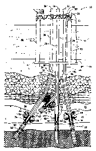
Referring to figure 1, a subsea template electromagnetic telemetry
system in use on an offshore oil and gas platform is schematically illustrated
and generally designated 10. A production platform 12 is centered over
submerged oil and gas formations 14, 15 located below sea floor 16. Wellheads
18, 20, 22 are located on deck 24 of platform 12. Wells 26, 28, 30 extend
through the sea 32 and penetrate the various earth strata including formations
14, 15, forming, respectively, wellbores 34, 36, 38, each of which may be
cased or
uncased. Wellbore 36 includes a lateral or branch wellbore 37 that extends
from
the primary wellbore 36. The lateral wellbore 37 is completed in formation 15
which may be isolated for selective production independent of production from
formation 14 into wellbore 36. Also extending from wellheads 18, 20, 22 are
tubing 40, 42, 44 which are respectively, disposed in wellbores 34, 36, 38.
Tubing 43 is disposed in lateral wellbore 37 and may join tubing 42 for
production therethrough.
Wells 26, 28, 30 along with legs 41, 45 extend through subsea template
47. Subsea template 47 helps to support platform 12 and allows for the
accurate positioning of wells 26, 28, 30. Extending outwardly from subsea
template 47 is coupling 49 which may be a ring, a post or the like. Coupling
49
is electrically connected to electrical wire 51 that extends through sea 32
and
terminates at surface installation 58. An electrical wire 60 connects surface
installation 58 to the conductor pipe of well 30. Thus, a complete electric
circuit
CA 02526193 1999-02-24
-9-
is formed that includes subsea template 47, coupling 49, electrical wire 51,
surface installation 58, electrical wire 60 and the conductor pipe of wel130.
Surface installation 58 may be composed of a computer system that
processes, stores and displays information relating to formations 14, 15 such
as
production parameters including temperature, pressure, flow rates and
oil/water
ratio. Surface installation 58 also maintains information relating to the
operational states of the various downhole devices located in wellbores 34,
36,
37, 38. Surface installation 58 may include a peripheral computer or a work
station with a processor, memory, and audiovisual capabilities. Surface
installation 58 includes a power source for producing the necessary energy to
operate surface installation 58 as well as the power necessary to generate a
current between electrical coupling 49 and well 30 through subsea template 47.
This current will, in turn, generate electromagnetic wave fronts 65. As such,
surface installation 58 is used to generate command signals that will operate
various downhole devices. Electrical wires 51, 60 may be connected to surface
installation 58 using an RS-232 interface.
As part of the final bottom hole assembly prior to production, a sonde 46
is disposed within wellbore 38. Likewise, sondes 48, 50, 53 are respectively
disposed within wellbores 36, 34, 37. Sonde 46 includes an electromagnetic
transmitter 52, an electronics package 54 and an electromagnetic receiver 56.
Also disposed in wellbore 38 are sensors 67 which may obtain, for example,
temperature, pressure, flowrate, or fluid composition data relating to
production
from formation 14. Thus, if the operator needs to obtain real time information
from formation 14, surface installation 58 would generate a request for
CA 02526193 1999-02-24
-10-
information by injecting a modulated current through subsea template 47
between coupling 49 and well 30. The current will produce the modulated
electric and magnetic fields of electromagnetic wave fronts 65 to communicate
the request to sonde 46. Electromagnetic wave fronts 65 are picked up by
electromagnetic receiver 56 of sonde 46 and passed on to electronics package
54
for processing and amplification. Electronics package 54 interfaces with
sensors
67 requesting the desired information.
Once sensors 67 obtain the information, the information is returned to
electronics packages 54 for processing. Electronics package 54 then
establishes
the frequency, power and phase output of the information prior to forwarding
the information to electromagnetic transmitter 52 of sonde 46 that radiates
electromagnetic wave fronts 64 into the earth. The electric field of
electromagnetic wave fronts 64 will generate a modulated current in subsea
template 47 between coupling 49 and well 30 which serve as electrodes for
sensing the voltage therebetween. The information then travels to surface
installation 58 via electrical wave 51. The information may then be processed
by surface installation 58 and placed in a useable format.
Alternatively, if the operator wanted to reduce the flow rate of production
fluids in well 28, surface installation 58 would be used to generate a command
signal to restrict the opening of bottom hole choke 62. The command signal
would be injected into subsea template 47 via electrical wire 51. The command
signal would then be radiated into the earth in the form of electromagnetic
wave
fronts 65. Electromagnetic wave fronts 54 are picked up by electromagnetic
receiver 66 of sonde 48. The command signal is then forwarded to electronics
CA 02526193 1999-02-24
- 11 -
package 68 of sonde 48 for processing and amplification. Electronics package
68
interfaces with bottom hole choke 62 and sends a driver signal to bottom hole
choke 62 to restrict the flow rate therethrough.
Once the flow rate in we1128 has been restricted by bottom hole choke 62,
bottom hole choke 62 interfaces with electronics package 68 of sonde 48 to
provide verification that the command generated by surface installation 58 has
been accomplished. Electronics package 68 then sends the verification signal
to
electromagnetic transmitter 70 of sonde 48 that radiates electromagnetic wave
fronts 72 into the earth which are picked up by subsea template 47 and passed
onto surface installation 58 via electrical wire 51 as describe above.
As another example, the operator may want to shut in production in
lateral wellbore 37. As such, surface installation 58 would generate the shut
in
command signal and inject it into subsea template 47. Electromagnetic wave
fronts 65 are then generated as described above. The shut in command would
be picked up by electromagnetic receiver 55 of sonde 53 and processed in
electronics package 57 of sonde 53. Electronics package 57 interfaces with
valve
59 causing valve 59 to close. This change in the operational state of valve 59
would be verified to surface installation 58 as described above, by radiating
electromagnetic wave fronts 61 from electromagnetic transmitter 63 which
generate a current in subsea template 47 that relays the verification to
surface
installation 58 via electrical wire 51.
Similarly, the operator may want to actuate a sliding sleeve in a selective
completion with sliding sleeves 74. A command signal would again be
generated by surface installation 58 and injected into subsea template 47 via
CA 02526193 1999-02-24
12-
electrical wire 51. Electromagnetic wave fronts 65 would then be generated,
thereby transmitting the command signal to electromagnetic receiver 76 of
sonde 50. The command signal is forwarded to electronics package 78 for
processing, amplification and generation of a driver signal. Electronics
package
78 then interfaces with sliding sleeves 80, 82 and sends the driver signal to
shut
off production from the lower portion of formation 14 by closing sliding
sleeve 82
and allow production from the upper portion of formation 14 by opening sliding
sleeve 80. Sliding sleeves 80, 82 interface with electronics package 78 of
sonde
50 to provide verification information regarding their respective changes in
operational states. This information is processed and passed to
electromagnetic
transmitter 84 which generates electromagnetic wave fronts 86.
Electromagnetic wave fronts 86 propagated through the earth and are picked up
by subsea template 47. The verification information is then passed onto
surface
installation 58 via electrical wire 51 for analysis and storage.
Each of the command signals generated by surface installation 58 is
uniquely associated with a particular downhole device such as bottom hole
choke 62, valve 59, sensors 67 or sliding sleeves 80, 82. Thus, as will be
further
discussed with reference to figures 9 and 10 below, electronics package 68 of
sonde 46 will only process a command signal that is uniquely associated with a
downhole device, such as bottom hole choke 62, located within wellbore 36.
Similarly, electronics package 57 of sonde 46 will only process a command
signal
that is uniquely associated with a downhole device, such as valve 59, located
within wellbore 37, while electronics package 54 of sonde 46 will only process
a
command signal that is uniquely associated with a downhole device, such as
CA 02526193 1999-02-24
-13-
sensors 67, located within wellbore 38 and electronics package 78 of sonde 50
will only process a command signal uniquely associated with a downhole device,
such as sliding sleeves 80, 82, located within wellbore 34. Thus, the subsea
template electromagnetic telemetry system of the present invention allows for
the monitoring of well data and the control of multiple downhole devices
located
in multiple wells from one central point.
Even though figure 1 depicts three wells 26, 28, 30 extending from a
single platform 12, it should be apparent to those skilled in the art that the
principles of the present invention are applicable to a single platform having
any number of wells or to multiple platforms so long as the wells are within
the
transmission range of the electromagnetic wave such as electromagnetic wave
fronts 65 from the master platform such as platform 12. It should be noted,
that
the transmission range of electromagnetic waves such as electromagnetic wave
fronts 65 is significantly greater when transmitting horizontally through a
single or limited number of strata as compared with transmitting vertically
through numerous strata. For example, electromagnetic waves such as
electromagnetic wave fronts 65 may travel between 3,000 and 6,000 feet
vertically while traveling between 15,000 and 30,000 feet horizontally
depending on factors such as the voltage, the frequency of transmission, the
conductance of the transmission media, and the level of noise. The
transmission
range of electromagnetic waves such as electromagnetic wave fronts 65 may be
extended, however, using electromagnetic repeaters that may extend either the
vertical or horizontal transmission range or both.
CA 02526193 1999-02-24
- 14-
Even though figure 1 depicts well 30 as completing the electrical circuit
between surface installations 58 and subsea template 47, it should be
understood by those skilled in the art that a variety of electrical
connections
could be used to complete the electrical circuit including, but not limited
to,
wells 26, 28, legs 41, 45 or other riser pipe in electrical contact with
subsea
template 47. Also, it should be understood by those skilled in the art that
the
current injected by surface installation 58 may travel either from well 30 to
coupling 49 or from coupling 49 to well 30 for the generation of
electromagnetic
wave fronts 65. Similarly, it should be understood by those skilled in the art
that the current generated between well 30 and coupling 49 by electromagnetic
waves such as electromagnetic wave fronts 61, 64, 72, 86 may travel either
from
well 30 to coupling 49 and up electrical wire 51 to surface installation 58 or
from
coupling 49 to well 30 and up the conductor pipe of well 30 to surface
installation 58.
Representatively illustrated in figures 2A-2B is a sonde 77 of the present
invention. For convenience of illustration, figures 2A-2B depict sonde 77 in a
quarter sectional view. Sonde 77 has a box end 79 and a pin end 81 such that
sonde 77 is threadably adaptable to other tools in a final bottom hole
assembly.
Sonde 77 has an outer housing 83 and a mandrel 85 having a full bore so that
when sonde 77 is disposed within a well, tubing may be inserted therethrough.
Housing 83 and mandrel 85 protect the operable components of sonde 77 during
installation and production.
Housing 83 of sonde 77 includes an axially extending and generally
tubular upper connecter 87. An axially extending generally tubular
CA 02526193 1999-02-24
-15-
intermediate housing member 89 is threadably and sealably connected to upper
connecter 87. An axially extending generally tubular lower housing member 90
is threadably and sealably connected to intermediate housing member 89.
Collectively, upper connecter 87, intermediate housing member 89 and lower
housing member 90 form upper subassembly 92. Upper subassembly 92 is
electrically connected to the section of the casing above sonde 77.
An axially extending generally tubular isolation subassembly 94 is
securably and sealably coupled to lower housing member 90. Disposed between
isolation subassembly 94 and lower housing member 90 is a dielectric layer 96
that provides electric isolation between lower housing member 90 and isolation
subassembly 94. Dielectric layer 96 is composed of a dielectric material, such
as
teflon,. chosen for its dielectric properties and capably of withstanding
compression loads without extruding.
An axially extending generally tubular lower connecter 98 is securably
and sealably coupled to isolation subassembly 94. Disposed between lower
connecter 98 and isolation subassembly 94 is a dielectric layer 100 that
electrically isolates lower connecter 98 from isolation subassembly 94. Lower
connecter 98 is electrically connected to the portion of the casing below
sonde
77.
It should be apparent to those skilled in the art that the use of
directional terms such as above, below, upper, lower, upward, downward, etc.
are used in relation to the illustrative embodiments as they are depicted in
the
figures, the upward direction being toward the top of the corresponding figure
and the downward direction being toward the bottom of the corresponding
CA 02526193 1999-02-24
-16-
figure. It is to be understood that the downhole component described herein,
for
example, sonde 77, may be operated in vertical, horizontal, inverted or
inclined
orientations without deviating from the principles of the present invention.
Mandrel 85 includes axially extending generally tubular upper mandrel
section 102 and axially extending generally tubular lower mandrel section 104.
Upper mandrel section 102 is partially disposed and sealing configured within
upper connecter 87. A dielectric member 106 electrically isolates upper
mandrel
section 102 from upper connecter 87. The outer surface of upper mandrel
section 102 has a dielectric layer disposed thereon. Dielectric layer 108 may
be,
for example, a teflon layer. Together, dielectric layer 108 and dielectric
member
106 serve to electrically isolate upper connecter 87 from upper mandrel
section
102.
Between upper mandrel section 102 and lower mandrel section 104 is a
dielectric member 110 that, along-with dielectric layer 108, serves to
electrically
isolate upper mandrel section 102 from lower mandrel section 104. Between
lower mandrel section 104 and lower housing member 90 is a dielectric member
112. On the outer surface of lower mandrel section 104 is a dielectric layer
114
which, along with dielectric member 112, provides for electric isolation of
lower
mandrel section 104 from lower housing number 90. Dielectric layer 114 also
provides for electric isolation between lower mandrel section 104 and
isolation
subassembly 94 as well as between lower mandrel section 104 and lower
connecter 98. Lower end 116 of lower mandrel section 104 is disposed within
lower connecter 98 and is in electrical communication with lower connecter 98.
Intermediate housing member 89 of outer housing 83 and upper mandrel
CA 02526193 1999-02-24
-17-
section 102 of mandrel 85 define annular area 118. A receiver 120, an
electronics package 122 and a transmitter 124 are disposed within annular area
118.
In operation, sonde 77 receives a command signal in the form of
electromagnetic wave fronts 65 generated by subsea template 47 of figure 1.
Electromagnetic receiver 120 forwards the command signal to electronics
package 122 via electrical conductor 126. Electronics package 122 processes
the
command signal as will be discussed with reference to figures 9 and 10 and
generates a driver signal. The driver signal is forwarded to the downhole
device
uniquely associated with the command signal to change the operational state of
the downhole device. A verification signal is returned to electronics package
122
from the downhole device and is processed and forwarded to electromagnetic
transmitter 124. Electromagnetic transmitter 124 transforms the verification
signal into electromagnetic waves which are radiated into the earth and picked
up by subsea template 47 and passed to surface installation 58 via electrical
wire 51.
Referring now to figure 3, a schematic illustration of a toroid is depicted
and generally designated 180. Toroid 180 includes magnetically permeable
annular core 182, a plurality of electrical conductor windings 184 and a
plurality
of electrical conductor windings 186. Windings 184 and windings 186 are each
wrapped around annular core 182. Collectively, annular core 182, windings 184
and windings 186 serve to approximate an electrical transformer wherein either
windings 184 or windings 186 may serve as the primary or the secondary of the
transformer.
CA 02526193 1999-02-24
-18-
In one embodiment, the ratio of primary windings to secondary windings
is 2:1. For example, the primary windings may include 100 turns around
annular core 182 while the secondary windings may include 50 turns around
annular core 182. In another embodiment, the ratio of secondary windings to
primary windings is 4:1. For example, primary windings may include 10 turns
around annular core 182 while secondary windings may include 40 turns
around annular core 182. It will be apparent to those skilled in the art that
the
ratio of primary windings to secondary windings as well as the specific number
of turns around annular core 182 will vary based upon factors such as the
diameter and height of annular core 182, the desired voltage, current and
frequency characteristics associated with the primary windings and secondary
windings and the desired magnetic flux density generated by the primary
windings and secondary windings.
Toroid 180 of the present invention may serve, for example, as
electromagnetic receiver 120 or electromagnetic transmitter 124 of figure 2.
The following description of the orientation of windings 184 and windings 186
will therefore be applicable to each of the above.
With reference to figures 2 and 3, windings 184 have a first end 188 and
a second end 190. First end 188 of windings 184 is electrically connected to
electronics package 122. When toroid 180 serves as electromagnetic receiver
120, windings 184 serve as the secondary wherein first end 188 of windings 184
feeds electronics package 122 with the command signal via electrical conductor
126. The command signal is processed by electronics package 122 as will be
further described with reference to figures 9, 10 below. When toroid 180
serves
CA 02526193 1999-02-24
-19-
as electromagnetic transmitter 124, windings 184 serve as the primary wherein
first end 188 of windings 184, receives the verification signal from
electronics
package 122 via electrical conductor 128. Second end 190 of windings 184 is
electrically connected to upper subassembly 92 of outer housing 83 which
serves
as a ground.
Windings 186 of toroid 180 have a first end 192 and a second end 194.
First end 192 of windings 186 is electrically connected to upper subassembly
92
of outer housing 83. Second end 194 of windings 186 is electrically connected
to
lower connecter 98 of outer housing 83. First end 192 of windings 186 is
thereby
separated from second end 192 of windings 186 by isolations subassembly 94
which prevents a short between first end 192 and second end 194 of windings
186.
When toroid 180 serves as electromagnetic receiver 120, electromagnetic
wave fronts, such as electromagnetic wave fronts 65 induce a current in
windings 186, which serve as the primary. The current induced in windings 186
induces a current in windings 184, the secondary, which feeds electronics
package 122 as described above. When toroid 180 serves as electromagnetic
transmitter 124, the current supplied from electronics package 122 feeds
windings 184, the primary, such that a current is induced in windings 186, the
secondary. The current in windings 186 induces an axial current on the casing,
thereby producing electromagnetic waves.
Due to the ratio of primary windings to secondary windings, when toroid
180 serves as electromagnetic receiver 120, the signal carried by the current
induced in the primary windings is increased in the secondary windings.
CA 02526193 1999-02-24
-20-
Similarly, when toroid 180 serves as electromagnetic transmitter 124, the
current in the primary windings is increased in the secondary windings.
Referring now to figure 4, an exploded view of a toroid assembly 226 is
depicted. Toroid assembly 226 may be designed to serve, for example, as
electromagnetic receiver 120 of figure 2. Toroid assembly 226 includes a
magnetically permeable core 228, an upper winding cap 230, a lower winding
cap 232, an upper protective plate 234 and a lower protective plate 236.
Winding caps 230, 232 and protective plates 234, 236 are formed from a
dielectric material such as fiberglass or phenolic. Windings 238 are wrapped
around core 228 and winding caps 230, 232 by inserting windings 238 into a
plurality of slots 240 which, along with the dielectric material, prevent
electrical
shorts between the turns of winding 238. For illustrative purposes, only one
set
of winding, windings 238, have been depicted. It will be apparent to those
skilled in the art that, in operation, a primary and a secondary set of
windings
will be utilized by toroid assembly 226.
Figure 5 depicts an exploded view of toroid assembly 242 which may
serve, for example, as electromagnetic transmitter 124 of figure 2. Toroid
assembly 242 includes four magnetically permeable cores 244, 246, 248 and 250
between an upper winding cap 252 and a lower winding cap 254. An upper
protective plate 256 and a lower protective plate 258 are disposed
respectively
above and below upper winding cap 252 and lower winding cap 254. In
operation, primary and secondary windings (not pictured) are wrapped around
cores 244, 246, 248 and 250 as well as upper winding cap 252 and lower winding
cap 254 through a plurality of slots 260.
CA 02526193 1999-02-24
-21-
As should be apparent from figures 4 and 5, the number of magnetically
permeable cores such as core 228 and cores 244, 246, 248 and 250 may be
varied, dependent upon the required length for the toroid as well as whether
the
toroid serves as a receiver, such as toroid assembly 226, or a transmitter,
such
as toroid assembly 242. In addition, as will be known by those skilled in the
art,
the number of cores will be dependent upon the diameter of the cores as well
as
the desired voltage, current and frequency carried by the primary windings and
the secondary windings, such as windings 238.
Turning next to figures 6, 7 and 8 collectively, therein are depicted the
components of an electronics package 195 of the present invention. Electronics
package 195 may serve as the electronics package used in the sondes described
above. Electronics package 195 includes an annular carrier 196, an electronics
member 198 and one or more battery packs 200. Annular carrier 196 is
disposed between outer housing 83 and mandrel 85. Annular carrier 196
includes a plurality of axial openings 202 for receiving either electronics
member 198 or battery packs 200.
Even though figure 8 depicts four axial openings 202, it should be
understood by one skilled in the art that the number of axial openings in
annular carrier 196 may be varied. Specifically, the number of axial openings
202 will be dependent upon the number of battery packs 200 that are required.
Electronics member 198 is insertable into an axial opening 202 of
annular carrier 196. Electronics member 198 receives a command signal from
first end 188 of windings 184 when toroid 180 serves as, for example,
electromagnetic receiver 120 of figure 2. Electronics member 198 includes a
CA 02526193 1999-02-24
-22-
plurality of electronic devices such as limiter 204, preamplifier 206, notch
filter
208, bandpass filters 210, phase lock loop 212, clock 214, shift registers
216,
comparators 218, parity check 220, storage device 222, and amplifier 224. The
operation of these electronic devices will be more full discussed with
reference to
figures 9 and 10.
Battery packs 200 are insertable into axial openings 202 of axial carrier
196. Battery packs 200, which includes batteries such as nickel cadmium
batteries or lithium batteries, are configured to provide the proper operating
voltage and current to the electronic devices of electronics member 198 and to
toroid 180.
Turning now to figure 9 and with reference to figure 1, one embodiment
of the method for processing the command signal is described. The method 500
utilizes a plurality of electronic devices such as those described with
reference to
figure 7. Method 500 provides for digital processing of the command signal
generated by surface installation 58 and transmitted via electromagnetic wave
fronts 65. Limiter 502 receives the command signal from electromagnetic
receiver 504. Limiter 502 may include a pair of diodes for attenuating the
noise
in the command signal to a predetermined range, such as between about .3 and
.8 volts. The command signal is then passed to amplifier 506 which may
amplify the command signal to a predetermined voltage suitable for circuit
logic,
such as 5 volts. The command signal is then passed through a notch filter 508
to shunt noise at a predetermined frequency, such as 60 hertz. The command
signal then enters a bandpass filter 510 to attenuate high noise and low noise
CA 02526193 1999-02-24
-23-
and to recreate the original waveform having the original frequency, for
example, two hertz.
The command signal is then fed through a phase lock loop 512 that is
controlled by a precision clock 513 to assure that the command signal which
passes through bandpass filter 510 has the proper frequency and is not simply
noise. As the command signal will include a certain amount of carrier
frequency
first, phase lock loop 512 will verify that the received signal is, in fact, a
command signal. The command signal then enters a series of shift registers
that perform a variety of error checking features.
Sync check 514 reads, for example, the first six bits of the information
carried in the command signal. These first six bits are compared with the six
bits stored in comparator 516 to determine whether the command signal is
carrying the type of information intended for a sonde, such as sondes 46, 48,
50,
53. For example, the first 6 bits in the preamble of the command signal must
carry the code stored in comparator 516 in order for the command signal to
pass
through sync check 514. Each of the sondes of the present invention, such as
sonde 46, 48, 50, 53 may use the same code in comparator 516.
If the first six bits in the preamble correspond with that in comparator
516, the command signal passes to an identification check 518. Identification
check 518 determines whether the command signal is uniquely associated with
a specific downhole device controlled by that sonde. For example, the
comparator 520 of sonde 48 will require a specific binary code while
comparator
520 of sonde 50 will require a different binary code. Specifically, if the
command
signal is uniquely associated with bottom hole choke 62, the command signal
CA 02526193 1999-02-24
-24-
will include a binary code that will correspond with the binary code stored in
comparator 520 of sonde 48.
After passing through identification check 518, the command signal is
shifted into a data register 520 which is in communication with a parity check
522 to analyze the information carried in the command signal for errors and to
assure that noise has not infiltrated and abrogated the data stream by
checking
the parity of the data stream. If no errors are detected, the command signal
is
shifted into storage registers 524, 526. For example, once the command signal
has been shifted into storage register 524, a binary code carried in the
command
signal is compared with that stored in comparator 528. If the binary code of
the
command signal matches that in comparator 528, the command signal is passed
onto output driver 530. Output driver 530 generates a driver signal that is
passed to the proper downhole device such that the operational state of the
downhole device is changed. For example, sonde 50 may generate a driver
signal to change the operational state of sliding sleeve 82 from open to
close.
Similarly, the binary code in the command signal stored in storage
register 526 is compared with that in comparator 532. If the binary codes
match, comparator 532 forwards the command signal to output driver 534.
Output driver 534 generates a driver signal to operate another downhole
device.
For example, sonde 50 may generate a driver signal to change the operational
state of sliding sleeve 80 from closed to open to allow formation fluids from
the
top of formation 14 to flow into well 26.
Once the operational state of the downhole device has been changed
according to the command signal, a verification signal is generated and
returned
CA 02526193 1999-02-24
-25-
to sonde 50. The verification signal is processed by sonde 50 and passed on to
electromagnetic transmitter 84 of sonde 50. Electromagnetic transmitter 84
transforms the verification signal into electromagnetic wave fronts 86, which
are radiated into the earth to be picked up by subsea template 47. As
explained
above, the verification signal is then forwarded to surface installation 58
via
electrical wire 51.
Even though figure 9 has described sync check 514, identifier check 518,
data register 520 and storage registers 524, 526 as shift registers, it should
be
apparent to those skilled in the art that alternate electronic devices may be
used
for error checking and storage including, but not limited to, random access
memory, read only memory, erasable programmable read only memory and a
microprocessor.
In figures 10A-B, a method for operating a subsea template
electromagnetic telemetry system of the present invention is shown in a block
diagram generally designated 600. The method begins with the generation of a
command signa1602 by surface installation 58. When the command signa1602
is generated, a timer 604 is set. If the command signal 602 is a new message
606, surface installation 58 initiates the transmission of command signa1602
in
step 608. If command signal 602 is not a new message, it must be
acknowledged in step 607 prior to being transmitted in step 608.
Transmission 608 involves sending the command signal 602 to subsea
template 47 via electrical wire 51 and generating electromagnetic wave fronts
65. The sondes listen for the command signal 602 in step 610. When a
command message 602 is received by a sonde in step 612, the command signal
CA 02526193 1999-02-24
-26-
602 is verified in step 614 as described above with reference to figure 9. If
the
sonde is unable to verify the command signal 602, and the timer has not
expired
in step 616, the sonde will continue to listen for the command signal in step
610.
If the timer has expired in step 616, and a second time out occurs in step
618,
the command signal is flagged as a bad transmission in step 620.
If the command signal 602 is requesting a change in the operational state
of a downhole device, a driver signal is generated in step 622 such that the
operational state of the downhole device is changed in step 624. Once the
operational state of the downhole device has been changed, the sonde receives
a
verification signal from the downhole device in step 626. If the verification
signal is not received, the sonde will again attempt to change the operational
state of the downhole device in step 624. If a verification signal is not
received
after the second attempt to change the operational state of the downhole
device,
in step 628, a message is generated indicating that there has been a failure
to
change the operational state of the downhole device.
The status of the downhole device, whether operationally changed or not,
is then transmitted by the sonde in step 630. The surface installation listens
for
the carrier in step 632 and receives the status signal in step 634, which is
verified by the surface installation in step 636. If the surface installation
does
not receive the status message in step 634, the surface installation continues
to
listen for a carrier in step 632. If the timer has expired in step 638, and a
second time out has occurred in step 640, the transmission is flagged as a bad
transmission in step 642. Also, if the surface installation is unable to
verify the
status of the downhole device in step 636, the surface installation will
continue
CA 02526193 1999-02-24
-27-
to listen for a carrier in step 632. If the timers in steps 638, 640 have
expired,
however, the transmission will be flagged as a bad transmission in step 642.
In addition, the method of the present invention includes a check back
before operate loop which may be used prior to the actuation of a downhole
device. In this case, command message 602 will not change the operational
state of a downhole device, in step 622, rather the sonde will simply
acknowledge the command signal 602 in step 644. The surface installation will
listen for a carrier in step 646, receive the acknowledgment in step 648 for
verification in step 650. If the surface installation does not receive the
acknowledgment in step 648, the surface installation will continue to listen
for a
carrier in step 646. If the timers have expired in steps 652, 654, the
transmission will be flagged as a bad transmission in step 620. Additionally,
if
the surface installation is unable to verify the acknowledgment in step 650,
the
surface installation will continue to listen for a carrier in step 646. If the
timers
in step 652 and step 654 have timed out, however, the transmission will be
flagged as a bad transmission in step 620.
While this invention has been described with a reference to illustrative
embodiments, this description is not intended to be construed in a limiting
sense. Various modifications and combinations of the illustrative embodiments
as well as other embodiments of the invention, will be apparent to persons
skilled in the art upon reference to the description. It is, therefore,
intended
that the appended claims encompass any such modifications or embodiments.
What is claimed is: