Note: Descriptions are shown in the official language in which they were submitted.
CA 02526330 2006-07-12
A CONTROL SYSTEM FOR A VERTICAL VANE COVERING
FOR ARCHITECTURAL OPENINGS
This application is a divisional of Canadian Patent Application 2,217,112
filed on September 30, 1997.
BACKGROUND OF THE INVENTION
Field of the Invention
The present invention relates generally to, coverings for
architectural openings such as doors, windows, and the like, and more
particularly to a control system for a covering having a plurality of
vertically suspended vanes linearly movable between extended and
retracted positions, as well as pivotally movable between open and closed
positions, to control visibility and the passage of light through the
architectural opening.
Description of the Rel vant Art
Covers for architectural openings such as doors, windows, and the
like have been known in various forms for many years. One form of such
covering is commonly referred to as a vertical vane covering wherein a
control system suspends and is operable to selectively manipulate a
plurality of vertically suspended vanes such that the vanes can be linearly
moved laterally across the architectural opening to extend or retract the
covering and can be pivoted about longitudinal vertical axes to open and
close the vanes.
Control systems for operating vertical vane coverings typically
include a headrail in which a plurality of carriers associated with each
vane are mounted for lateral movement, and include internal
mechanisms for pivoting the vanes about their vertical axes. The
headrails vary in construction and configuration to house the various
types of carriers, but typically the headrails are relatively large and
rectangular in cross section to enclose the working components of the
system. Many such headrails have a slot along a bottom wall through
which a portion of each carrier protrudes for connection to an associated
vane.
CA 02526330 1997-09-30
-_-J
2
Most control systems include pull cords that are operably connected
to the carriers to shift or linearly move the carriers horizontally along the
headrail and across the architectural opening. Control systems also
usually include a horizontally disposed tilt rod operably connected to each
carrier such that rotational movement of the tilt rod about its longitudinal
axis transfers corresponding movement to the carriers and subsequently to
the vanes to effect pivotal movement of the vanes about their
longitudinal vertical axes. The tilt rod is typically rotated by a pull cord
or
a tilt wand that can be grasped by an operator of the system.
Considerable attention has been given to the configuration and
construction of headrails as they are readily visible in vertical vane
coverings. U.S. Patent No. 4,361,179 issued to Benthin, for example,
discloses a headrail having an opening through the top thereof so as to
improve the aesthetics of the headrail. The primary components of each
carrier in the system are confined within the interior of the headrail and
generally "C" shaped hangers associated with each carrier circumscribe the
headrail so as to be in a position to support an associated vane from
beneath the headrail.
Carriers in vertical vane coverings may be interconnected by a
pantograph so that movement of an endmost or lead carrier causes all of
the carriers to move correspondingly. One problem with prior art control
systems has been the manner in which the carriers are connected to the
pantograph. Typically, due to the central connection system and
expansion of the pantograph upon movement of the lead carrier, the other
carriers are caused to skew slightly resulting in increased friction and
making them more difficult to move along the length of the tilt rod.
Another shortcoming in prior art systems which utilize pull cords
to move the lead carrier is the fact that the pulleys for returning -and
deflecting the pull cords are normally relatively small in size thereby
requiring multiple revolutions to allow significant movement of the
carriers which increases system friction and imposes unnecessary wear on
the system.
CA 02526330 1997-09-30
3
Another problem with prior art control systems resides in the fact
that they are difficult to assemble inasmuch as the drive mechanism of the
carriers associated with the vanes must be uniformly aligned and operably
connected to the tilt rod so that pivotal movement of the tilt rod moves
the vanes between associated and corresponding angular positions.
Accordingly, if the carriers are not mounted on the tilt rod uniformly, the
vanes will not be properly aligned and uniformly angularly related to the
architectural opening. As will be appreciated, in order to properly align
and uniformly angularly relate the vanes to the architectural opening, the
carriers have to be carefully and uniformly mounted on the tilt rod, which
can be a time consuming endeavor.
Still another prevailing problem with prior art control systems for
vertical vane coverings resides in the fact that the vanes are suspended in
spaced relationship from the bottom of the headrail thereby establishing a
gap that allows undesired light to pass between the top edge of the vanes
and the bottom of the headrail. While the window covering itself may
adequately block the passage of light through the architectural opening,
this spaced relationship of the top edge of the vanes with the headrail
undesirably permits the passage of light through the gap.
Since the pull cords utilized to move the lead carrier along the
length of a tilt rod apply a significant force to. the lead carrier which, in
tum, expands or contracts the pantograph to effect corresponding
movement of the other carriers, it will be appreciated that a skewing of the
lead carrier can also be a problem depending upon the spacing of the pull
cords from the tilt rod on which the carriers are mounted. Skewing of the
lead carrier which increases drag on the system has traditionally also been
a problem in prior art systems.
As will be appreciated from the above, drag in a control system
resulting from friction between the various relatively movable parts has
been a drawback. Accordingly, a need exists in the art for a low friction
system that is easy to operate and is more durable for extended
maintenance-free operation.
CA 02526330 1997-09-30
4
Another shortcoming in many prior art systems relates to the design of the
headrail. The design and configuration of the headrail, as may not be readily
appreciated, can create problems for an installer of vertical vane coverings.
Many
headrails used in vertical vane coverings are non-symmetric in transverse
cross section
in order to accommodate in a compact manner the working components of the
associated
control system. Examples of such headrails are disclosed in U.S. Patent No.
5,249,617
issued to Durig, U.S. Patent No. 4,381,029 issued to Ford, et al., and U.S.
Patent No.
4,381,029 issued to Ford, et al. While such systems may compactly accept the
associated
components of the control system, they are many times undesirable from an
installation
standpoint as they can only be installed in one orientation. If a headrail is
blemished or
marred, for example, on an outer visible surface, it is usually deemed
unusable.
It is to overcome the aforenoted shortcomings in the prior art systems that
the
present invention has been developed.
SUMMARY OF THE INVENTION
The control system of the present invention is adapted for use in a covering
for
an architectural opening wherein the covering includes a plurality of
vertically
suspended vanes adapted to be uniformly disposed across the architectural
opening or
selectively retracted to one side of the opening. The control system is also
adapted to
selectively pivot the vanes about longitudinal vertical axes of the vanes so
as to move the
vanes between an open position wherein they extend perpendicularly to the
architectural
opening and in parallel relationship with each other, and a closed position
wherein they
lie parallel with the architectural opening and in substantially overlapping
coplanar
relationship with each other.
The control system has been uniquely designed for ease of assembly by an
installer of the system and for ease of operation by a user. As in most
vertical vane
systems, a typical embodiment of the present invention includes an elongated
tilt rod that
is confined within and supported by a headrail for rotative movement about its
longitudinal axis. The tilt rod is operatively connected to a plurality of
carriers disposed
along its length, each of which suspends a separate vane, and wherein the
carriers
include a gear system driven by the tilt rod and adapted to selectively pivot
the
CA 02526330 1997-09-30
suspended vanes about their longitudinal axes. The tilt rod has a longitudinal
groove
adapted to cooperate with a mating projection on a gear within each carrier so
as to
facilitate uniform connection of the tilt rod with each carrier such that the
vanes can be
moved in unison between corresponding angles relative to the architectural
opening for
5 desired operation of the system.
The carriers are slidably mounted on the tilt rod for movement along the
length
of the tilt rod and are operably interconnected by a pantograph or scissors-
type connector
so that linear movement of any carrier along the tilt rod effects
corresponding movement
of the remaining carriers so that the vanes are, in turn, slidably moved
across the window
covering in unison. A pull cord system for selectively expanding or
contracting the
pantograph to correspondingly expand or retract the vanes across the
architectural
opening includes a traverse cord that is suspended along one side of the
covering for
operation, and is operably connected through a pulley system to a lead carrier
for
expansion and contraction of the pantograph and, thus, the covering. The lead
carrier is
a carrier at one end of the assemblage of carriers, and is the carrier that
has full
movement from one side of the architectural opening to the other as the
covering is
expanded or retracted by the traverse cord. The lead carrier, as well as the
remaining
standard carriers, has been uniquely designed so that the traverse cord is
connected to the
lead carrier in very close proximity to the tilt rod so as to minimize skewing
of the lead
carrier relative to the tilt rod upon pulling forces being applied to the lead
carrier by the
traverse cord. The traverse cord is preferably an elongated cord that is
rendered endless
by connection of the two ends of the cord to the lead carrier.
The tilt rod has been coated with a low friction material to further
facilitate easy
sliding movement of the carriers along the tilt rod.
Each standard carrier is uniquely designed to include a pocket or passage
through
which the traverse cord can freely extend. In one embodiment the pocket has a
flexible
side wall so that the cord can be inserted into the pocket by flexing the
flexible side wall,
but the flexible side wall is resilient and naturally returns to its original
position to retain
the cord within the pocket. This arrangement prevents drooping cords as has
been a
problem with conventional control systems.
CA 02526330 1997-09-30
6
Each carrier, with the exception of the lead carrier, has a pair of rollers
adapted to
ride on tracks provided internally along the length of the headrail so that
the carriers
move substantially friction free along the headrail.
Each carrier has a pair of engaged gears with one gear being a worm gear
mounted on the tilt rod for unitary rotation therewith, and the second gear
being a pinion
gear associated with a hanger pin from which a vane is suspended. The carriers
have
been designed so that the pantograph interconnection with the carriers is
centered over
the tilt rod so as to minimize skewing of the carriers on the tilt rod upon
expansion and
contraction of the pantograph.
Each hanger pin has a pair of depending legs adapted to capture a vane
therebetween. The vane is provided with an opening near its upper edge and one
leg of
the hanger pin has a hook that is removably received within the aperture so
that the vane
is suspended from one leg of the hanger pin. The hanger pin itself is uniquely
designed
so that the leg which bears the weight of the vane is relatively large in
comparison to the
other confining leg in contrast to conventional systems. The confining leg,
which does
not have a weight bearing function but merely captures the vane to prevent
inadvertent
release, is relatively thin and the overall weight of the pin has accordingly
been reduced.
The reduction in weight of the pin, however, has been obtained while obtaining
an
increase in strength by desirably distributing the weight of the pin onto the
weight
bearing leg.
The headrail for the control system has been uniquely designed so as to be
transversely symmetric so that it can be installed in either direction without
affecting the
appearance or operation of the system. The headrail has a longitudinal slot
along a
bottom wall, and retention grooves along either side thereof to support and
retain a light
blocking rail, which extends downwardly from the headrail in close proximity
to the top
edge of the suspended vanes so as to substantially block the passage of light
between the
bottom of the headrail and the top of the vanes.
The pulleys used in the pull cord system have a diameter that is large
relative to
pulleys used in conventional systems, which not only improves the durability
of the
pulleys as they do not rotate through as many revolutions during operation of
the
CA 02526330 1997-09-30
7
covering, but in addition make the covering easier to operate, which is
desirable from the
user's standpoint.
Other aspects, features, and details of the present invention can be more
completely understood by reference to the following detailed description of a
preferred
embodiment, taken in conjunction with the drawings, and from the appended
claims.
BRIEF DESCRIPTION OF THE DRAWINGS
Fig. 1 is a fragmentary isometric view looking down on the control system of
the
present invention in use in connection with a covering for an architectural
opening.
Fig. 2 is a fragmentary isometric similar to Fig. 1 looking upwardly at the
control
system.
Fig. 3 is an exploded fragmentary isometric illustrating the internal
operational
components of the control system with the carriers having been eliminated.
Fig. 4 is an isometric looking down on elements of the control system without
the
headrail and illustrating the connection of the pantograph to a plurality of
carriers, and
with the pantograph in a retracted position.
Fig. 5 is an isometric looking down on the pantograph and interconnected
carriers with the pantograph in an expanded position, and with the tilt rod
shown in
dashed lines.
CA 02526330 1997-09-30
_ --;
- - -~
8
Fig. 6 is an isometric showing the connection of the pantograph
with a single carrier.
Fig. 7 is an enlarged exploded isometric view showing the
connection of the pantograph with a single carrier.
Fig. 8 is an enlarged section taken along line 8-8 of Fig. 2.
Fig. 9 is an enlarged fragmentary section taken along line 9-9 of
Fig. 2.
Fig. 10 is an enlarged section taken along line 10-10 of Fig. 2 with a
suspended vane shown in dashed lines and illustrating light-blocking rails
mounted on the headrail.
Fig. 10A is a fragmentary isometric view of one form of blocking
profile that is attachable to the headrail to block the passage of light
between the headrail and the suspended vanes.
Fig. 11 is an operational view similar to Fig. 10 showing the
mounting of the headrail to a supporting beam.
Fig. 12 is an isometric view of a mounting bracket used to secure the
headrail to a supporting beam.
Fig. 13 is a vertical section through a hanger pin showing the
operatively engaged worm gear on the tilt rod shown in dashed lines.
Fig. 14 is an isometric view showing an alternative lead carrier for
the system of the present invention.
Fig. 15 is a fragmentary isometric view of the lead carrier of the
primary embodiment and a standard carrier mounted on the tilt rod and
showing the pull cords and pantograph operatively connected therewith.
Fig. 16 is a fragmentary isometric view showing one end of the
control system and weighted tassels for operating the control cords.
Fig. 17 is a fragmentary isometric view showing an alternative
weighted tassel with the core separated from the outer shell.
Fig. 18 is a diagrammatic section taken through a modified
embodiment of the operating system of the present invdntion showing a
standard carrier and an electric motor operatively connectable to the tilt
rod to selectively pivot the carriers.
CA 02526330 1997-09-30
. - - _-) --'.
9
Fig. 19 is an exploded isometric of the lead carrier in the primary
embodiment showing the component parts of the lead carrier.
Fig. 20 is a bottom plan view of the preferred embodiment of the
lead carrier.
Fig. 21 is an exploded isometric view of an alternative mounting
plate and end cap at one end of the headrail looking down on the headrail.
Fig. 22 is an isometric looking up from the bottom of the mounting
plate shown in Fig. 21.
Fig. 23 is an enlarged end elevation showing the opposite side of the
mounting plate as shown in Fig. 22.
Fig. 24 is an isometric view of the control system of the present
invention illustrating an alternative embodiment using a bead chain for
tilting the vanes.
Fig. 25 is an enlarged section taken through the headrail of Fig. 24
illustrating an alternative embodiment of a carrier in the control system.
Fig. 26 is an isometric view of the alternative embodiment of the
carrier with phantom line representations of the pantograph connected
thereto and the traverse cord extending therethrough.
Fig. 27 is an enlarged top plan view of the carrier shown in Fig. 26.
Fig. 28 is a section taken along line 28-28 of Fig. 27.
Fig. 29 is an isometric view of an alternative embodiment of a tassel
for use in connection to a bead chain used in the control system of the
present invention.
Fig. 30 is an enlarged front elevation of the tassels shown in Fig. 29.
Fig. 31 is a vertical section taken through the tassel as shown in Fig.
30.
Fig. 32 is a view taken along line 32-32 of Fig. 30.
Fig. 33 is a section taken along line 33-33 of Fig. 31.
Fig. 34 is an isometric view of an alternative embodiment of the
pantograph used in the control system of the present invention with
phantom line representations of carriers connected thereto and a traverse
cord.
CA 02526330 1997-09-30
--i -- .
Fig. 35 is an isometric view looking up at the bottom of a male link
in the pantograph of Fig. 34.
Fig. 36 is a bottom plan view of the male link shown in Fig. 35.
Fig. 37 is a section taken along line 37-37 of Fig. 36.
5 Fig. 38 is an isometric view of the top of the female link of the
pantograph of Fig. 34.
Fig. 39 is an isometric looking at the bottom of the female link of
Fig. 38.
Fig. 40 is an enlarged bottom plan view of the female link of Fig. 38.
10 Fig. 41 is a longitudinal section taken along line 41-41 of Fig. 40.
Fig. 42 is an isometric view of a lock collar used to secure the tilt rod
in the end cap at one end of the headrail.
Fig. 43 is an isometric view of the lock collar secured to the end of
the tilt rod and with the end cap and a portion of the headrail shown in
phantom lines.
Fig. 44 is an exploded fragmentary view of the lock collar of Fig. 42
with an end of the tilt rod and a fastening screw shown in phantom lines.
Fig. 45 is an end elevation of the lock collar shown in Fig. 42.
Fig. 46 is a section taken along line 46-46 of Fig. 45.
Fig. 47 is an isometric view of an anchor plate for securing the ends
of the traverse cord to the lead carrier in the control system of the present
invention.
Fig. 48 is an isometric view looking up from the bottom of the top
bracket used in conjunction with a conventional carrier to define the lead
carrier and with the anchor plate being shown removed therefrom.
Fig, 48A is an isometric view looking downwardly on the top
bracket shown in Fig. 48 and with a standard carrier shown removed from
the top bracket and in phantom lines.
Fig. 49 is a bottom plan view of the anchor plate of Fig. 47 with the
top bracket of a lead carrier shown in phantom lines.
Fig. 50 is a section taken along line 50-50 of Fig. 49.
CA 02526330 1997-09-30
11
Fig. 51 is a fragmentary bottom plan view of a cord support system
with the system in a nonsupporting position.
Fig. 52 is a fragmentary bottom plan view similar to Fig. 51 with the
support system in a supporting position.
Fig. 53 is an isometric view looking up from the bottom of the base
component of the support system of Fig. 51.
Fig. 54 is an enlarged bottom plan view of the base shown in Fig. 53.
Fig. 55 is a section taken along line 55-55 of Fig. 54.
Fig. 56 is an isometric view looking downwardly on the support
arm of the support system shown in Fig. 51.
Fig. 57 is a fragmentary isometric looking at the bottom of the
support arm shown in Fig. 56.
Fig. 57A is an isometric view of the cord support system of Fig. 51
looking downwardly and with the support system in a supporting
position.
Figs. 58A through 58C are diagrammatic operational views showing
the operation of the cord support of Fig. 51.
Fig. 59 is an isometric view of the cord support system of Fig. 58
looking upwardly from the bottom and with the cord support system
incorporated into the headrail of the control system of the present
invention which is shown in phantom lines.
Fig. 60 is an isometric view of a cord tensioning system for the
traverse cord of the control system of the present invention and with parts
removed for clarity.
Fig. 61 is a section taken along line 61-61 of Fig. 62.
Fig. 62 is a fragmentary vertical section taken through the bracket
and the anchor pin of the system shown in Fig. 60 with the bracket
mounted on a horizontal surface.
Fig. 63 is a vertical section similar to Fig. 62 with the bracket
mounted on a vertical surface.
CA 02526330 1997-09-30
12
Fig. 65 is a fragmentary enlarged section taken along line 65-65 of
Fig. 64.
Fig. 66 is an enlarged view taken along line 66-66 of Fig. 65.
Fig. 67 is an enlarged section taken along line 67-67 of Fig. 65.
Fig. 68 is an isometric view looking down from the top of an
alternative bracket for supporting the headrail of the control system of the
present invention from a supporting surface and with the headrail shown
in phantom lines.
Fig. 69 is an isometric view looking up from the bottom of the
bracket shown in Fig. 68 with a support for the bracket being shown in
phantom lines.
Fig. 70 is a bottom plan view of the bracket shown in Fig. 69.
Fig. 71 is an enlarged section taken along line 71-71 of Fig. 70.
DESCRIPTION OF THE PREFERRED EMBODIMENTS
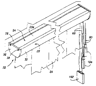
The headrail 20 and other portions of the control system 22 of the
present invention are shown in Figs. 1 and 2 with vertical covering
segments, hereafter referred to as vanes 24 but which might assume other
configurations, being suspended from carriers 26 in the system in adjacent
side by side relationship. For purposes of clarity, the vanes are shown in
dashed lines in Fig. 2. The headrail for the control system is designed to
extend completely across the top of an architectural opening (not shown),
and be suspended in a manner to be described hereafter from a beam or
other supporting structure at the top of the architectural opening. While
not being illustrated, the control system 22 is adapted to move the vanes 24
from a retracted position wherein the vanes are horizontally stacked
adjacent one side of the architectural opening to an extended position
wherein the vanes are evenly distributed across the architectural opening.
In the extended position the vanes are adapted to be pivoted about
longitudinal vertical axes between open positions wherein they extend
perpendicularly to the architectural opening and in parallel spaced
CA 02526330 1997-09-30
13
relationship to a closed position as illustrated in Figs. 1 and 2, with the
vanes overlapping -and being substantially coplanar with each other.
The headrail 20, as can be appreciated in Figs. 1 and 2, is symmetric
relative to a longitudinally extending vertical plane bisecting the headrail
or, in other words, is symmetric in a transverse direction relative to the
vertical plane. The headrail, as probably best seen in Fig. 3, has a main
body 28 with arcuate downwardly convergent side walls 30 that are spaced
at the top and bottom so as to define an open longitudinally extending slot
32 in the bottom and a longitudinally extending relatively broad groove 34
in the top. End caps 36 are securable with suitable fasteners 38 to each end
of the main body for closure purposes.
The slot 32 in the bottom of the headrail 20 permits hanger pins 40,
forming part of the carriers 26 to protrude downwardly from the headrail
and thereby suspend in a manner to be described later associated vanes 24
at a spaced distance beneath the headrail. Control cords forming part of an
operating system also depend through the open slot at one end of the
headrail as will be appreciated from the description that follows.
In addition to the headrail 20, the control system 22 includes an
elongated, horizontally extending tilt rod 42 (Fig. 3) with a cord operated
system for rotating the tilt rod about its longitudinal axis, a plurality of
the
aforenoted carriers 26 which are slidably mounted on the tilt rod and
operatively associated therewith for pivoting the vanes about longitudinal
vertical axes, and a pantograph 44 interconnecting the carriers such that
movement of a lead carrier 26L (Fig. 15) along the length of the tilt rod by a
pull cord mechanism causes each of the standard carriers 26S to follow in
desirably spaced relationship with each other. The pantograph, which
forms part of an operating system with the pull cords and the tilt rod for
manipulating the carriers, is probably best illustrated in Figs. 6 and 7.
With reference to the exploded view in Fig. 3, the headrail 20 is
illustrated with the end caps 36 having been removed from opposite ends
thereof. Mounting plates 46 are securable to the end caps and. are shown
being properly positioned for supporting the operative components of the
CA 02526330 1997-09-30
14
controls for pivoting the tilt rod 42 about its longitudinal axis, and for
selectively expanding and retracting the pantograph 44. More specifically,
at the left end of the headrail a mounting plate 46L is illustrated having a
substantially cylindrically shaped bearing 48 with a cylindrical passage 50
therethrough. Adjacent to the cylindrical passage is a substantially "H"
shaped slot 52 formed in a thickened section 54 of the mounting plate,
with the slot 52 having a divider plate 56. The mounting plate 46 in cross
section is identically shaped to the end cap, and is securably mounted
thereto with the screw-type fasteners 38 that pass through openings in the
mounting plate and are threadedly received in channels 58- formed in the
main body of the headrail.
A dual pulley 60 with independently movable individual pulley
segments 62 and 64 (as best seen in Fig. 3) is mounted in the H-shaped slot
52 in a vertical orientation and rotatably maintained in the slot by a pivot
pin 66 that extends through the thickened section 54 on the mounting
plate in which the H-shaped slot is formed to retain the dual pulley within
the slot. The dual pulley, as will be described in more detail later, receives
a traverse cord 68 used to move the carriers 26 along the length of the
headrail.
The cylindrical passage 50 in the bearing 48 rotatably receives a
barrel-shaped insert 70 (Fig. 3) having a large diameter portion 72 and a
smaller diameter portion 74. The insert is hollow defining a relatively
small diameter opening 76 through the smaller diameter portion 74 and a
larger diameter opening 78 in the large diameter portion 72 of the insert.
The smaller diameter opening 76 is adapted to slidably receive, but
substantially conform in configuration and dimension with, one end of
the tilt rod 42 so as to receive and support the end of the tilt rod for
unitary
rotation therewith. The large diameter portion 72 of the barrel insert
defines a drum around which a tilt cord 80 extends. The tilt cord is
wrapped around the drum to prevent slippage and so that the opposite
ends of the cord 80 (Fig. 16), which depend from the drum, can be pulled to
selectively rotate the drum about its longitudinal axis in either direction.
CA 02526330 1997-09-30
_-, --.
The passage 50 through the cylindrical bearing 48 in the mounting plate
46L has large and small diameter portions to mate with the barrel insert so
that the barrel insert is prevented from sliding through the bearing by a
shoulder 83 (Fig. 3) on the barrel insert defined between the large and
5 smaller diameter portions. The bearing on the mounting plate is slotted at
84 through the bottom so that both ends of the tilt cord 80 can hang
therethrough.
An alternative form of the mounting plate is shown in Figs. 21
through 25 and identified 46'. In the mounting plate 46', it can be seen to
10 have an H-shaped slotted opening 85 to receive the dual pulley 60 in the
same manner as described with the mounting plate 46. Again, the dual
pulley supports the traverse cord 68 which is adapted to move the carriers
and thus the suspended vanes across the architectural opening. Adjacent
to the H-shaped slotted opening, a cylindrical bearing 87 projects from one
15 side of the plate to rotatably receive and support one end of the tilt rod
42.
The cylindrical bearing has an enlarged cylindrical cavity 89 coaxial
therewith which opens on the opposite side of the mounting plate. The
cylindrical cavity is adapted to rotatably support a bead wheel guide 91
which is keyed in any suitable manner to the end of the tilt rod for unitary
rotation therewith. The bead wheel guide has a scalloped periphery
defining a plurality of adjacent cups which are sized and adapted to
releasably receive beads 93 of a conventional beaded chain 95. The
interaction of the beads with the cups in the periphery of the bead wheel
guide allows longitudinal movement of the beaded chain to rotate the
bead wheel guide and consequently rotate the tilt rod about its
longitudinal axis to pivot the vanes about their longitudinal axes as will be
described in more detail later. The mounting plate 46' also has a pair of
longitudinally extending fingers 97 on opposite sides adapted to be
received in the end of longitudinal channels of the headrail to align the
mounting plate with the end of the headrail. The mounting plate 46' is
secured to the headrail as with the mounting plate 46 by the screw-type
fasteners 38 that pass through openings in the end cap and the mounting
CA 02526330 1997-09-30
. = . \~ -_)
16
plate to secure the mounting plate in place. The end cap, of course, also
confines the bead wheel guide 91 within the cylindrical cavity 89. Figs. 24
and 25 show the headrail with the beaded chain 95 in the control system
and with the beaded chain (Fig. 24) hanging adjacent to the traverse cord at
one end.
The opposite or right end of the headrail, as best seen in Fig. 3,
similarly has a mounting plate 46R with a cylindrical bearing 86 having a
reduced diameter cylindrical protrusion 88. The bearing 86 defines a
cylindrical passage 90 therethrough adapted to rotatably receive the
opposite end of the tilt rod 42 which is predominantly rigid but slightly
flexible. A gusseted bracket 92 also projects inwardly from the mounting
plate and has a horizontal slot 94 therein adapted to rotatably support a
horizontal pulley 96 that rotates about a pivot pin 98 received in the
bracket_ Again, the mounting plate 46R is secured to the associated end cap
36 with screw-type fasteners 38 that are inserted into and threadedly
received in the channels 58 at the opposite end of the headrail. The
horizontal pulley 96 receives the traverse cord 68 which is preferably an
elongated cord that is effectively rendered endless by its connection to the
lead carrier 26L in a manner to be described later. Both the horizontal
pulley 96 and the dual pulley 60 are of relatively large diameter (i.e.
approximately .608 inches) in comparison to pulleys used in most
conventional systems which has been found to make the system easier to
operate and extends the life of the component parts.
As mentioned previously, there are a plurality of carriers 26
disposed along the length of the headrail and slidably mounted on the tilt
rod 42 for pivotal movement of the vanes 24 suspended from the carriers.
The carriers are uniform in construction 'with the exception of the lead
carrier 26L which is, in the preferred embodiment and as best seen in Figs.
9, 15, 19 and 20, merely a modification of a standard carrier 26S through the
addition of a snap-on carrier plate 100. The lead carrier will be described in
more detail later.
CA 02526330 1997-09-30
17
Each carrier 26, probably best seen in Fig. 7, inCludes a main body
102, a hanger pin 40 having a pinion gear 104 on its uppermost end, a
worm gear 106, and a pair of roller wheels 108. The main body is
substantially hollow, having a pair of side walls 110, a flat end wall 112, a
bottom wall 114, and an arcuate opposite end wall 116 from which a
gusseted extension 118 forms a lateral extension. A connector in the form
of a pivot pin 120 is formed on the top of one side wall 110 to enable
attachment of the carrier to the pantograph 44. The gusseted bracket 118
and the flat end wall 112 each have stub shafts 122 formed thereon to
rotatably receive an associated snap-on roller wheel 108. Mounted on the
distal end of the gusseted bracket and on the flat end wall are horizontal
slides in the form of substantially flat extension plates or ledges 124 (Figs.
7
through 9) which cooperate with the associated roller wheels in guiding
movement of the carrier along the headrail 20, as will also be explained
hereafter.
Aligned circular openings 126 are provided through the side walls
110 in a vertical plane with the pivot pin 120, which are of a diameter
substantially the same as the outside diameter of the tilt rod 42 so as to
rotatably receive the tilt rod. The worm gear 106 is mounted on the tilt rod
within the interior of the carrier and is keyed to the tilt rod with an
inwardly directed generally V-shaped protrusion 128 (Figs. 7 through 9)
that is received in a longitudinally extending V-shaped groove 130 in the
tilt rod. The worm gear, therefore, rotates in unison with the tilt rod.
The hanger pin 40, as best seen in Figs. 7 and 13, is elongated and of
generally cylindrical configuration defining the pinion gear 104 at its
uppermost end, a central cylindrical body portion 132, and a pair of spaced
depending legs 134 and 136 which are adapted to support the uppermost
end of an associated vane 24. The hanger pin is pivotally mounted within
the arcuate end wall 116 of the carrier body with a shoulder 138 at the
lower end of the pinion gear being supported upon an inwardly directed
rim (Fig. 7) projecting inwardly from the inner cylindrical wall of the
CA 02526330 1997-09-30
18
arcuate section. The depending legs, therefore, protrude from the bottom
of the main body. -
Looking specifically at Fig. 13, one leg 134 of each hanger pin 40,
which will be referred to herein as the supporting leg, has a hook shaped
projection 142, and the body of the support leg is relatively thick in
comparison to the other leg 136, which will be referred to as the confining
leg. The confining leg 136 has a beaded lower end 144 so that a relatively
thin channel 146 between the two legs opens downwardly to receive the
uppermost edge of an associated vane 24 that has a transverse opening 148
(Fig. 2) therethrough adapted to be received upon and supported by the
hook-shaped projection on the support leg. The confining leg urges the
vane toward the support leg so that it does not inadvertently become
released from the hanger pin. It is important to note that the confining
leg, not having a supportive role, has been made relatively thin in
comparison to the supporting leg thereby reducing the material used'in
the hanger pin. This reduction in material has been achieved while
increasing the thickness of the supporting leg in cornpaiison to
conventional hanger pins so as to obtain approximately a 28% increase in
strength while reducing the overall weight and cost'of the pin. The
average thickness of the supporting leg in the preferred embodiment is in
the range of .095 to .105 inches, while the thickness of the upper end of the
confining leg is in the range of .075 to .085.
When the hanger pin 40 is disposed within the main body, the
pinion gear 104 is meshed with the worm gear 106 so that rotational
movement of the worm gear about its horizontal axis effects pivotal
movement of the hanger pin about its vertical axis. The tilt rod 42, which
rotates the worm gear, thereby effects pivotal movement of the vane
suspended from the hanger pin.
As mentioned previously, the pantograph 44 is a mechanism that
operatively interconnects each carrier 26 so that movement of the lead
carrier 26L causes a corresponding movement of the standard or following
carriers 26S thereby uniformly distributing the vanes across the
CA 02526330 1997-09-30
, -~
19
architectural opening or retracting the vanes adjacent to one side of the
opening. The pantograph, as best seen in Figs. 4 through 7, has a plurality
of pivotally interconnected links 150 which are interconnected in a
scissors-like manner. There are two sets of links 152A and 152B, with each
set having a plurality of parallel links angularly related to the links of the
other set. A link 152A of one set is pivotally connected at a midpoint to an
associated link 152B of the other set, and the end of each link in a set is
pivotally connected to the end of a link in the other set. One set of links
152B has a plurality of apertures 154 provided therethrough and one
aperture.154A (Fig. 7) is offset from the center and substantially equally
spaced or centered between the midpoint and one end of the link. The
offset aperture is adapted to pivotally receive and be retained on the pivot
pin 120 mounted on one side wall 110 of a carrier so that the link pivots
about the pivot pin upon expansion or retraction of the pantograph. It is
important to note and appreciate that the pivot pin 120 is vertically aligned
with the tilt rod 42. In this manner, when the pantograph 44 is expanded
or contracted causing the links to move longitudinally of the headrail 20,
the force applied to the carrier 26 by the pantograph is along the tilt rod so
that the carrier is not torqued or otherwise pulled in a manner that might
cause the carrier to skew relative to the tilt rod. This connection causes a
smooth gliding movement of the carriers along the tilt rod. To further
improve the sliding movement, the tilt rod is preferably coated with a low
friction material such as polyester so that there is a reduced resistance to
movement.of the carrier along the tilt rod.
As probably best seen in Fig. 8, the gusseted extension 118 on each
standard carrier 26S is defined by an upper plate 156,and an intermediate
plate 158 connected to the arcuate end wall 116 of the main body, as well as
a vertical or distal end plate 160 interconnecting the distal ends of the
upper and intermediate plates and protruding downwardly therefrom.
The distal end plate 160 has one of the stub shafts 122 for the roller wheels
108 mounted on an outer face thereof and an inwardly projecting flexible
horizontal finger 162 spaced downwardly frcm the intermediate plate 158.
CA 02526330 1997-09-30
-,.
The flexible finger has a fixed end and a free end with the free end being
spaced slightly, i.e. a distance slightly less than the diameter of the
traverse
cord 68, from the outer surface of the arcuate wall. It will be appreciated
that a pocket or passage 164 is defined between the flexible finger 162, the
5 intermediate plate 158, the outer surface of the arcuate end wall 116 and
the distal end plate 160, which pocket is adapted to slidably receive and
confine the traverse cord used in moving the carriers along the length of
the headrail. The flexible finger is resilient so as to permit the cord to be
inserted through the gap between the finger and the arcuate end wall, but
10 the finger is rigid enough to retain the cord within the pocket after
having
been flexed so that if slack were to ever form in the cord, the cords would
not droop from the pocket. In other words, the pocket confines the cord so
that it will not distractively droop, for example, through the slot 32 formed
in the headrail where it would otherwise be undesirably visible.
15 In an alternative form of the carrier identified by the reference
number 26' and shown best in Figs. 26 through 28, it will be seen that the
carrier is identical to carrier 26 except that horizontal finger 162 of
carrier
26 has been replaced with a downwardly angled finger 165 having a
vertical lip 167 which underlies the tip of a horizontal finger 169 that
20 projects away from the main body of the carrier. A small gap 171 is
provided between the angled finger 165 and the horizontal finger 169
through which the traverse cord 68 can be inserted. A reinforcing plate 173
interconnects the lower end of distal end plate 160' with intermediate plate
158' and cooperates with the intermediate plate, the angled finger and the
horizontal finger in defining a pocket 175 which releasably confines the
control cord to prevent it from drooping through the open bottom of the
headrail.
With further reference to Fig. 8, it will be appreciated that the
arcuate side walls 30 of the headrail 20 have inwardfy directed substantially
horizontal protrusions or tracks 166 formed near the vertical center of the
headrail. The tracks are adapted to support the roller wheels 108 so that
the carriers can roll along the length of the headrail when moved by the
CA 02526330 1997-09-30
21
pantograph 44. The horizontal extension ledge 124 on the distal end plate
160 of each carrier 26 is spaced beneath the overlying roller wheel so as to
accommodate an associated track on the headrail. The carrier is, therefore,
confined on the tracks for movement therealong by guide elements in the
form of the roller wheels 108 and slides 124 which stabilize the carriers
relative to the headrail. Either the carrier or the tracks can be coated with
a
low friction material to facilitate an easy sliding movement of the carriers
with polyester being a suitable coating for this purpose.
In the primary embodiment of the present invention, the lead
carrier 26L is merely a modified standard carrier 26S, as is probably best
illustrated in Figs. 9, 15 and 19. As is probably best seen in Fig. 19, the
lead
carrier 26I. comprises a standard carrier 26S and the snap-on carrier plate or
top bracket 100 which is releasably connected to the standard carrier. The
top bracket 100 has a main body portion 170 defining a top plate 172, a pair
of depending side plates 174, and a pair of depending intermediate plates
176, which extend in parallel with the length of the headrail 20. On one
side of the main body portion, a generally U-shaped member 178 is formed
which is slightly wider than the main body portion. On the horizontally
extending legs 180 of the U-shaped member 178, elongated ovular
horizontally oriented slots 182 are provided to releasably receive the stub
shafts 122 on which the roller wheels 108 are mounted for the standard
carrier 26S. In other words, on the Iead carrier 26L, the roller wheels are
either removed or not fitted and the stub shafts are snapped into the slots
182 on the horizontal legs of the bracket, which are resilient enough to
allow the insertion of the stub shafts. Along the bottom edge of the legs
180 and the bottom edge of the side plates 174 are slides in the form of
lateral, flat, plate-like protrusions 184 which are adapted to overlie the
tracks 166 while the horizontal ledge 124 on the standard carrier body
underlies the track of the headrail. In this manner, the lead carrier is
confined for sliding movement along the tracks similarly to the standard
carriers and, again, a coating of polyester or the like on the tracks provides
a desirable low friction surface to facilitate an easy sliding movement.
CA 02526330 1997-09-30
22
As probably best illustrated in Fig. 9, the space between a side plate
174 and an intermediate plate 176 on the main body portion 170 of the top
bracket 100 of the lead carrier 26L defines a downwardly opening channel
185 in which segments of the traverse cord 68 are aligned. The outermost
segment 68A of the traverse cord passes through this channel 185, while
the innermost segment 68B of the cord is diverted so as to extend between
the two intermediate plates 176 where that particular cord segment 68B,
which defines one end of the traverse cord, is secured to the lead carrier by
a screw-type fastener 186 which is threaded from beneath into a boss 188
provided on the top plate. The outermost segment 68A of the cord which
passes through the channel 185 extends to the far end of the headrail
where it passes around the horizontal pulley 96 and returns with the
opposite end of the traverse cord 68 being secured to the lead carrier 26L by
the second one of two screws, Fig. 20, that is threaded from beneath into a
second boss 188 on the top bracket. Accordingly, the traverse cord, which is
an elongated cord, has two ends which are anchored to the lead carrier so
that the cord forms or defines an endless loop securecl to the lead carrier so
that the lead carrier moves in unison with the cord. Of course, as
mentioned previously, movement of the lead carrier causes a
corresponding movement of the remaining standard, or follower, carriers
26S due to their interconnection with the pantograph 44.
The traverse cord loop extends at one end of the headrail around
the horizontal pulley 96 and at the opposite end of the headrail, around
the two halves of the vertical dual pulley 60, and from the dual pulley
hangs downwardly and passes around a free or dangling vertically
oriented pulley 190 (Fig. 16) within a weighted or spring-biased housing
192 (Figs. 1 and 16), which retains the cord in a taut condition. As will be
appreciated, when one of the depending portions of the traverse cord is
pulled, the lead carrier 26L is caused to slide in'a first longitudinal
direction relative to the headrail 20, while pulling movement of the
opposite portion of the cord causes sliding movement in the opposite
direction. Movement in one direction of the lead carrier, of course,
CA 02526330 1997-09-30
23
extends the vanes across the architectural opening, while movement in
the opposite direction retracts the vanes adjacent to one side of the
opening.
Tilting or pivotal movement of the vanes 24 about their vertical
axes is effected through rotational movement of the tilt rod 42, as was
mentioned previously, with this movement being caused by movement of
the tilt cord 80, which is wrapped around the barrel insert 70 at the control
end of the headrail. While not required, in the disclosed embodiment the
tilt cord has two ends which are suspended adjacent to each other and
support a weighted tassel 194 (Figs. 1 and 16) so as to hold each cord in a
vertical and taut condition. Pulling a tassel 194 at one end of the cord
obviously pivots the tilt rod in one direction, while pulling the tassel at
the opposite end of the cord rotates the tilt rod in the opposite direction.
Through the intermeshing of the worm gear 106 and pinion gears 104.
within each carrier 26, the vanes suspended from the carriers are caused to
rotate in one direction or the other in iinison and in alignment with each
other.
While the weighted tassels 194 could take on numerous
configurations, Fig. 16 shows a tassel being made of a relatively heavy
material, such as zinc or Zomac alloy, having a longitudinal hole 196
therethrough which receives one end of the tilt cord 80 which can be
knotted to prevent the tassel from slipping from the cord. In an
altemative embodiment shown in Fig. 17, an interior core 198 of a
relatively heavy material such as zinc, having an axial passage 200
therethrough to receive the tilt cord 80 can be utilized with the cord being
knotted at one end to prevent release of the core and an outer shell 202 of
possibly a more aesthetically attractive material being slidably received
over the core.
A tassel 203 designed for suspension from the end of the beaded
chain 95 is illustrated in Figs. 29 through 33 and again is desirably made of
a relatively heavy material such as zinc or Zomac alloy. As will be
appreciated, the tassel is shown in hexagonal cross-sectional configuration
CA 02526330 1997-09-30
- ~ -
24
even though other configurations would also be appropriate. The tassel is
elongated having an upper crown 205 of smaller tapered diameter relative
to the lower main body 207. There are three interconnected vertically
aligned chambers with an upper small chamber 209 opening through the
top and through one side 211 of the upper crown. The upper chamber
overlaps the next adjacent lower vertically aligned intermediate chamber
213 that opens through the opposite side 215 of the upper crown. The
overlap between the two chambers defines a passage 217 between the
chambers that is large enough to accommodate the size of a bead in the
beaded chain 95 to which the tassel is connected. The lower wall 219 of the
intermediate chamber 213 is slotted with the slot 221 opening through the
side of the tassel and with the wall 219 being of a thickness to fit between
two adjacent beads in a beaded chain and with the slot being of a size to
slidably receive the thin connector 223 between beads in a chain. The
lowermost chamber 225 which lies beneath the slotted wall 219 receives
the free end of the beaded chain with the slotted wall retaining the beaded
chain to the tassel and with the beaded chain passing upwardly through
the passage 217 between the upper and intermediate chambers and out the
open top of the tassel. The side wall 215 of the uppei chamber encourages
the beaded chain to stay confined within the slot in the wall even though
the chain can be manually removed so that the tassel can be attached to or
removed from the beaded chain or adjusted in length as desired.
As mentioned previously, the headrail 20 is provided with a broad
groove 34 along its upper surface, with the groove formed by a depressed
plate portion 204 (Figs. 1 and 11) vertically spaced from overhanging ledges
206 on the top of the headrail. The space between the ledges 206 and the
depressed plate portion 204 define pockets 208 adapted to cooperate with a
mounting plate 210 (Figs. 11 and 12), which is securable to a beam 212 or
other structural member above an architectural opening. The mounting
plate, as best seen in Figs. 11 and 12, has a flat plate-like main body 214
with
openings 216 through a top plate 218 thereof adapted to receive screw-type
fasteners 220 to secure the plate to the supporting beam. The plate has a
CA 02526330 1997-09-30
-~ --~
. -,
generally U-shaped connector 222 on one side with notches 224 on the free
ends of legs 226 of the connector and plate-like horizontal extensions 228
extending in the opposite direction. The horizontal extensions 228 overlie
and are spaced from a hook-shaped projection 230 from the bottom of the
5 top plate. The horizontal extensions are spaced above the hook-shaped
projection 230 so as to define a pocket 232 adapted to receive one of the
overhanging ledges 206 of the headrail, while the other overhanging ledge
206 is received in the notches 224 in the free ends of the legs 226 on the U-
shaped connector. When connecting the headrail to the mounting plate,
10 one overhanging ledge 206 is inserted into the notches on the U-shaped
connector and the headrail is then pivoted, as shown in Fig. 11, until the
overhanging ledges are horizontally aligned, with the second horizontal
ledge being snapped into the pocket 232 between the hook-shaped
projection 230 and the horizontal extensions 228. The headrail can be
15 removed from the mounting plate in a reverse procedure, with it being
understood that the hook-shaped projection is flexible enough to be
moved out of blocking alignment with the overhanging ledge.
The lower surface of the headrail 20, as best seen in Fig. 10, defines
two parallel ledges 234. The innermost extent of each ledge has an
20 inverted hook-shaped protrusion 236 which confronts an inwardly
directed protrusion 238 from the associated arcuate side wal130. The two
protrusions define a pocket therebetween. Each pocket is adapted to
receive a portion of a light-blocking rail or gap-restricting profile 240,
which extends longitudinally of the headrail. The light blocking rail, as
25 best seen in Fig. 10A, has an inverted V-shaped channel 242 formed along
one side, with laterally directed edges adapted to extend beneath the
protrusions 236 and 238 on the headrail. The edges thereby support the
light- blocking rail and incorporate it into the headrail so that an angled
flange 243 which extends downwardly through the longitudinal slot 32 in
the headrail at an acute angle to horizontal from the associated ledge 234
on the bottom plate substantially fills the gap between the bottom of the
headrail and the top of the suspended vanes. The flange 243 thereby forms
CA 02526330 1997-09-30
---=j l
26
a light-blocking barrier to light which might pass beneath the headrail 20
but above the top edge of the vanes 24. The angle of the light-blocking
flange prevents damage to the vanes in the event they swing about their
connection to the hanger pins, such as in air currents passing through the
architectural opening, as the vanes would then engage the light blocking
rail at a non-damaging angle.
The depending angled flange 243 is interconnected with a
horizontal leg 244 of each light-blocking rail, which in tum has an
upturned lip 246 on its innennost end. The horizontal intumed leg 244
need not be continuous along the length of the light-blocking bar so as to
save material costs and to increase flexibility. The horizontal leg 244
functions as a tilt rod support which prevents the tilt rod from sagging
beneath the headrail when the carriers are drawn to one side. When the
carriers are distributed along the length of the tilt rod, they too assist in
supporting the tilt rod through their support on the tracks 166.
In an alternative embodiment of the invention, as shown
schematically in Fig. 18, the headrail 20A is enlarged vertically so as to
define a pocket 248 above the depressed plate portion 204 in which an
electric motor or motors 250 can be mounted and used to operate the
traverse cord and/or tilt rod for automated operation of the control
system. The manner in which the motor or motors would be connected to
the tilt rod or to the cords would be within the skill of one in the art and,
therefore, has not been described in detail.
As was mentioned previously, the lead carrier 26L in the preferred
embodiment is simply a standard carrier 26S having been modified with
the inclusion of a top bracket or carrier plate 100. An alternative lead
carrier 252 is shown in Fig. 14. The lead carrier'252 is a single unit
comprised of a hollow main body 254 which pivotally supports a hanger
pin 40 with a pinion gear 104 that is meshed with a worm gear 106 through
which the tilt rod 42 extends and is keyed for unitary rotative movement.
These portions of the lead carrier are the same as described in connection
with lead carrier 26L. The main body includes a channe1256 through
CA 02526330 1997-09-30
. --~ -=~
27
which both segments of the traverse cord 68 enter and only the outer
segment 68A passes through for further extension around the horizontal
pulley 96 at the end of the headrail. The inner segment 68B of the traverse
cord is secured in a central downwardly opening channel 258 of the lead
carrier by a set screw 260 threaded into a boss 262 formed on the carrier
main body, while the returning outer segment 68A of the traverse cord
enters the same downwardly opening channel 258 from the opposite
direction, and is also secured in the channel by a set screw (not seen) that
is
threaded into a second boss 264 provided on the main body of the carrier.
The main carrier body has two outwardly opening, horizontally disposed
V-shaped brackets 266 having lower edges 268 that are adapted to slide
along the tracks 166 of the headrail. The V-shaped brackets are elongated
so as to cooperate with the elongated side walls 30 of the headrail in
keeping the carriers from skewing relative to the tilt rod as the carrier is
moved along the length of the headrail by the pantograph. Accordingly,
the elongated V-shaped channels add still another system for assuring
alignment of the carriers to facilitate free sliding movement for ease of
operation of the system.
A second embodiment 270 of a pantograph for use in the present
invention is illustrated in Figs. 34 through 41. As will be appreciated, the
pantograph includes male and female links 272 and 274 respectively which
are pivotally interconnected with each other and with the female link
being additionally pivotally connected with the protrusion 120' on a carrier
26'. The female link 274 is best seen in Figs. 38 through 41 to include a
first
set of three openings 276 and a second pair of openings 278 positioned
between adjacent openings 276 of the first set. The three openings in the
first set are positioned at opposite ends of the link and at its longitudinal
center. The link is thickened with bosses 280 at each opening 276. The
bosses project from the top surface of the link with the bottom surface
being substantially flat. Within each boss, there is a frustoconical surface
282 that tapers inwardly for a purpose to be described later. Beyond the
tapered surface is a relatively large cylindrical recess 284 which
CA 02526330 1997-09-30
28
communicates with the frustoconical surface. Each of the openings 278 in
the pair of openings is a mirror image of the other and includes a
cylindrical passage 286 with a rectangular keyway 288 extending completely
through the link. The keyways extend from the cylindrical passage toward
the center of the link as best seen in Fig. 40.
The male link 272, as best seen in Figs. 35 through 37, has a
relatively flat top surface and three downwardly projecting pins 290 which
have semi-circular lips 292 projecting in opposite longitudinal directions.
The semi-circular lips are separated by a slot 294 which allows the lips to
flex inwardly toward each other for purposes of being releasably snap
connected to a female link as will be described hereafter. When
connecting a male link to a female link as shown in Fig. 34, the pins 290 on
the male link are advanced against the frustoconical surface 282 of a
desired opening in the female link and the frustoconical surface cams the
lips of the pin toward each other until they pass through the reduced
diameter of the frustoconical surface. Upon reaching the relatively large
cylindrical recess 284 the lips expand thereby being pivotally captured
within an opening 276 in the female link. The male and female links are
thereby pivotally interconnected. The protrusion 120' on the top of each
carrier 26' has a rectangular tab 296 (Fig. 27) which is sized to fit through
the keyway 288 of the circular openings 278 in the female member. Once
the tab has been inserted through the keyway, the carrier is rotated slightly
and is thereby releasably and pivotally locked to the associated female link.
Due to the relationship of the female links to the carriers, once the system
is mounted in the headrail the keyway will not become aligned with the
tab and, therefore, the female links will not be accidentally released from
the carriers. With the male and female links interconnected with each
other and with the female links connected to the carriers as illustrated in
Fig. 34, the entire pantograph with the connected carriers is desirably
assembled for maintenance-free operation.
It has been found in relatively long coverings that the tilt rod 42 has
enough flex that it will sometimes be 'feleased from the bearing 86 in the
CA 02526330 1997-09-30
29
mounting plate 46. To prevent the tilt rod from being released, a lock
collar 298, best seen in Figs. 42 through 46, has been designed to be
connected to the end of the tilt rod and rotatably seated within a cavity 300
in the large cylindrical portion of the bearing 86 previously described in
connection with Fig. 3. The anchor.collar 298 is a cylindrical member
having a cylindrical passageway 302 of slightly larger diameter than the tilt
rod extending therethrough. The cylindrical passageway has an axially
extending threaded groove 304 which is alignable with the longitudinal V-
shaped groove in the tilt rod 42 so that the groove 130 in the tilt rod and
the threaded groove in the cylindrical passageway complement each other
to define a cylindrical hole into which a threaded screw-type fastener 306
can be advanced. As is best seen in Figs. 42 and 45, the center of the
defined hole is substantially aligned with the edge of the cylindrical
passageway 302 through the collar so that when the screw-type fastener is
advanced into the defined hole, the head of the screw overlies the end of
the collar whereby the screw is prevented from being pulled through the
collar and the tilt rod, which is now self-threadedly`engaged with the
screw, is also prevented from being pulled out of the collar. In this
manner, with the collar seated within the bearing 86; the tilt rod cannot be
released from the mounting plate even on relatively long headrails that
incorporate relatively long tilt rods.
An alternative system for anchoring the ends of the pull cord to the
lead carrier is illustrated in Figs. 47 through 50. An anchor plate 308, as
best seen in Fig. 47, includes an elongated substantially rectangular base 310
having an enlarged square head 312 at one end with transverse serrations
314 formed therein and an upstanding cylindrical pin 316 at the opposite
end. The enlarged square head has a circular hole 318 therethrough
adapted to receive a screw-type threaded fastener 320. As described
previously in connection with Figs. 15, 19, and 20, the ends of the traverse
cord 68 were secured to the lead carrier 26L with a pair of screw-type
fasteners with each of the fasteners pinching and end of the cord between
the head of the screw-type fastener and the main body of the carrier.
CA 02526330 1997-09-30
When utilizing the alternative arrangement, the carrier 26' is joined to a
top bracket 100' that is similar to the top bracket 100 described previously.
The top bracket 100' has a single threaded hole 322 at the approximate
location of the two holes in the bosses,188 of the previously described top
5 bracket 100. The screw-type fastener 320 shown in Figs. 48 and 50 is
adapted to pass through the hole 318 in the relatively large square head of
the anchor plate and be threadedly received in the single threaded hole
322. The anchor plate is positioned such that the serrated head overlies
both ends of the pull cord 68 and the upstanding cylindrical pin 316 is
10 abutted against a wall 317 of the carrier, as best shown in Figs. 49 and
50. In
this manner, the anchor plate lies between two partitions on the lead
carrier which prevent lateral displacement of the anchor plate while the
cylindrical pin prevents longitudinal movement. Once the screw-type
fastener 320 is advanced through the opening in the anchor plate and into
15 the threaded hole 322 in the top bracket 100', the serrated head pinches
the
ends of the traverse cord against a pair` of teeth 324 formed on the top
bracket 100' thereby preventing cord displacement. In doing so, the
rectangular base of the anchor plate 308 is bent or flexed as shown in Fig.
50, and is securely positioned so that the cord will not be released until the
20 screw-type fastener is removed. The top bracket 100' also has a pair of
depending trigger pins 326 for a purpose to be defined hereafter.
It has been found on relatively long headrails that when the vanes
and carriers 26' are all positioned to one side of the headrail as when the
covering in an open position, the traverse cord 68 will sometimes sag and
25 be visible through the bottom of the headrail. While, as mentioned
previously, the traverse cord is supported by each of the carriers, when the
covering is in an open position, the carriers are all stacked adjacent one
side of the headrail thereby leaving the cords unsupported along
substantially the remaining length of the headrail. Figs. 53 through 59
30 illustrate a cord support 328 which is operative to support the cords along
the length of the headrail when the carriers are retracted into an open or
CA 02526330 1997-09-30
31
substantially open position, but which are rendered inoperative when the
lead carrier passes thereby as the covering is being closed.
The cord support 328 includes two pieces, a base piece 330 and a
pivot or support arm 332. The base piece is anchorable at any selected
location along the length of the headrail to one of the lips adjacent the slot
32 in the bottom of the headrail. The base piece includes four tabs with
one set of two tabs 334 being longitudinally aligned along one side of the
base and another set of two tabs 336 being slightly laterally offset but
similarly longitudinally aligned so that a straight line gap is established
between the first set of tabs and the second set. The lip of the headrail is
positioned in the straight line gap and the base is thereby secured to the
headrail at any selected location along the length of the headrail. The base
has a depending pin 338 with an enlarged head and a slot therethrough so
that the head can flex inwardly to allow the pivot arm 332 to be pivotally
connected to the base.
The pivot arm 332 can be seen to have a relatively long and
substantially straight shank 340 and an enlarged head 342 having a circular
passage 344 therethrough adapted to pivotally receive the pin 338 on the
base. The enlarged head 342 on the support arm also has a small
projection or catch arm 346 extending angularly relative to the shank and
defining a pocket in the enlarged head between the catch arm and the
shank. The catch arm extends laterally a small distance beyond the side of
the shank for a purpose to be described hereafter. The support arm 332 is
adapted to swing through a 90 degree arc between a position extending
perpendicularly to the base 330 and transversely of the headrail wherein it
underlies the traverse cord 68 and supports the same and a second position
extending parallel with the base and in longitudinal alignment with the
headrail along one side of the slot in the bottom of the headrail. It will be
appreciated particularly by reference to:Figs. 54 and 56, that the base has a
depending elongated bead 348 of triangular cross-section extending
transversely and aligned with the pivot pin 338, while the top side of the
support arm has complementing criss-crossing grooves 350 that are also of
CA 02526330 1997-09-30
32
triangular cross-section. The bead 348 in the base and the grooves 350 in
the support arm are adapted to be releasably matingly engaged when the
support arm is in either its supporting position or its nonsupporting
position, and there is enough give in the pivot pin relative to the support
arm to allow the arm to be releasably- retained in position by the mating
engagement of the bead 348 with one or the other of the perpendicular
grooves 350.
Figs. 58A through 58C are diagrammatic operational views showing
how the support arm 332 is operatively engaged by the lead carrier 26L to
move the support arm between the supporting and nonsupporting
positions. In Fig. 58A, the support arm is shown in its supporting position
with the lead carrier passing thereby from right to left. The trigger pins 326
on the lead carrier engage the shank 340 of the support arm causing it to
pivot in a clockwise direction, as shown in Fig. 58B. After the carrier
passes completely by the support arm, it is fully pivoted and releasably
retained in its nonsupporting position of Fig. 58C, until the carrier passes
from left to right. When passing from left to right, which is not
illustrated, one of the trigger pins 326 on the lead carrier passes along the
side edge of the shank of the support arm until it engages the catch arm
346, and upon engaging the catch arm pivots the support arm in a
counterclockwise direction from its nonsupporting position of Fig. 58C to
its supporting position of Fig. 58A. The support arm is then again in
position to support the pull cords when the carriers are not present at that
location.
As mentioned previously, the pull or traverse cord 68 hangs in a
loop from one end of the headrail with the cord in the first described
embodiment passing around a pulley within a weighted housing 192 (Fig.
1). The housing illustrated in Fig. 1, for example, is simply a puIley
positioned within an outer shell that is preferably weighted to hold the
pull cord in a vertical position but in some instances, it is desirable to
tension the pull cord. A system 352 for tensioning the pull cord is shown
in Figs. 60 through 63, and can be seen to include an anchor bracket 354
CA 02526330 1997-09-30
33
that can be mounted on a horizontal or vertical surface and a housing 356
including a pulley 357 around which the pull cord extends, an anchor pin
358 and a coil spring 360 surrounding the anchor pin. The housing has a
cavity 362 with a transverse shaft 364 that rotatably supports the pulley 357
as shown in Fig. 60, and an elongated cylindrical cavity 366 that confines
the anchor pin and the coil spring which is axially positioned thereon.
The anchor pin 358 has an enlarged head 368 at its upper end and a
hook 370 at the lower end. The housing 356 further includes a shoulder
371 that engages the lower end of the coil spring with the upper end of the
coil spring engaging the enlarged head 368 so as to confine the coil spring
within the housing. The hook 370 of the anchor pin projects downwardly
beyond the lower end of the housing and is adapted to be pivotally
connected to the anchor bracket 354.
The anchor bracket 354 has a pair of spaced parallel side walls 372
and an end wall 374 connecting the side walls so as to define a cavity
therebetween, a horizontal cross shaft 376-extends between the side walls
and forms a pivot anchor for the hook of the anchor pin. As will be
appreciated, the cavity between the sid'e walls opens in two mutually
perpendicular directions out of two ends 378 and 380 of the bracket so that
the bracket can be mounted on a horizontal surface as shbwn in Fig. 62 or a
vertical surface as shown in Fig. 63 with the anchor pin protruding out of
the cavity through one of the open ends. It will be appreciated that in
operation, the anchor pin can be extended down and hooked around the
cross shaft 376 to releasably secure the housing to the bracket. The coil.
spring 360, of course, biases the housing downwardly and toward the
bracket placing a tension in the pull cord.
In recent years there has been increased emphasis on making pull
cords less amenable to child mishaps which are caused when the cords
hang loosely and are separated thereby defining a gap between the cords
into which a child can insert a body part. Figs. 64 through 67 illustrate a
system 382 for removing the gap between the cords which consists of
utilizing a elongated wand 384 with frictionally retained end caps 386 and
CA 02526330 1997-09-30
34
388 at the top and bottom end respectively. The wand 384 includes
longitudinally extending grooves 390 on diametrically opposite sides and
the caps at opposite ends of the wand are adapted to confine the cord at the
ends of the wand and encourage the cord to remain within the
longitudinally extending grooves 390. The cap 386 at the upper end of the
wand is spaced only a small distance from the headrail of the window
covering and has a large substantially cylindrical passage 392 therethrough
adapted to frictionally receive the end of the wand. The top end cap
further includes a pair of laterally displaced passages 394 of ovular cross-
section through which the cord slidably passes with these slots being
aligned with the longitudinal grooves 390 in the wand. The lower end cap
388 is similar to the upper end cap in shape and configuration but in
addition includes a pulley 396 rotatably supported therein and around
which the pull cord extends. Of course, the pulley 396 is aligned with the
grooves in the wand as well as the ovular slots 398 in the lower end cap.
The length of the looped pull cord depending from the headrail is
predetermined to substantially conform with the length of the wand so
that the cords are restrained within the grooves provided in the wand but
can be gripped by an operator of the window covering and separated from
the wand enough to allow the operator to pull the cord in either direction.
It will also be apparent that the cord tensioner illustrated in Figs. 60
through 63 could also be incorporated as the lower end cap for the wand
with only slight modifications.
As an alternative to the bracket 210 described previously for
mounting the headrail to an overlying beam or other structural member, a
bracket 400 as shown in Figs. 68 through 71 can be used. The bracket is
again adapted to be connected to and between the overhanging ledges 206
on the top of the headrail. As mentioned previously, the space between
ledges 206 and the depressed plate portion 204 define pockets 208 adapted
to cooperate with the mounting plate: The mounting plate 400 has a flat
plate-like main body 402 with openings 404 therethrough adapted to
receive screw-type fasteners 406 to secure the plate to the supporting beam
CA 02526330 1997-09-30
or other structural member. The plate-like main body has a generally U-
shaped connector 408 on one side with notches 410 on the free ends of legs
412 of the connector and transversely extending side walls 414 having
notches 416 in the ends opposite the U-shaped connector. The notches 416
5 in the side walls are adapted to engage and receive one overhanging ledge
206, while the notches 410 in the U-shaped connector are adapted to
receive the opposite overhanging ledge 206 so that the bracket is releasably
connectable to the ledges thereby supporting the headrail from the
overlying support beam.
10 It will be appreciated from the above that a control system for a
vertical vane covering for an architectural opening has been described in
various embodiments which has a number of advantages over prior art
systems. Due to the alignment of the connection of the pantograph 44
with each carrier 26 over the tilt rod 42, skewing of the carriers is
15 minimized. Similarly, the formation of pockets in each carrier to receive
the traverse cords and position the cords closely adjacent to the tilt rod
also
minimizes skewing so that the carriers are enabled to move easily along
the headrail and the tilt rod. A low friction coating bf the tilt rod further
enhances the easy sliding movement.
20 The longitudinal groove 130 in the tilt rod, which cooperates with
the protrusion on the worm gear 106 in each carrier, facilitates an easy
assembly of the system in that the relative positioning of the worm gear
106 and pinion gear 104 can be made on each carrier so that the vanes
associated with each carrier are positioned uniformly angularly. With this
25 uniform relationship, an insertion of the tilt rod through the worm gears
in each carrier allows the vanes to be very easily mounted and angularly
aligned upon assembly.
The light blocking rails 240 are also easily connected to the headrail
20 and positioned in an aesthetically attractive position to not only
30 substantially block the passage of light between the headrail on the top
edge of the vanes 24 but in a manner such that the vanes are not damaged
should they swing about `heir connection to the hanger pins.
CA 02526330 1997-09-30
36
The relatively large pulleys 60 and 96 used on the traverse cord
enable an easy operation of the system while minimizing wear and heat
generation to extend the life of the system. Further, the headrail 20 itself
is
symmetric about a longitudinal vertical central plane so that it can be
mounted in either direction. This not only makes the system easy to
mount, but also facilitates hiding a marred or blemished side wall of a
head rail thereby salvaging headrails that might not be usable in other
systems.
Although the present invention has been described with a certain
degree of particularity, it is understood that the present disclosure has been
made by way of example, and changes in detail or structure may be made
without departing from the spirit from the invention, as defined in the
appended claims.