Note: Descriptions are shown in the official language in which they were submitted.
CA 02526958 2005-11-15
1090P125CA01
Steering System for Vehicles
This invention relates to a steering system for vehicles with at least three
independently steerable wheels and a steering setpoint transmitter steering
the
wheels by means of a selectable steering program, for instance a steering
wheel.
=
A wide variety of flexible steering systems for wheel-bound vehicles are known
already. While usual passenger cars and trucks generally have a front axle
steering and rigid rear wheels, special vehicles are known for special
applications,
which achieve a very high maneuverability in that steering systems with
different,
firmly defined steering programs can be selected. Such special vehicles, which
must have a particularly good maneuverability, are for instance working
machines,
as they are used for instance in the aluminum and steel industries, or floor
conveyors for in-house transport. The same can include for instance crucible
charging vehicles, trough charging machines, scooping vehicles, crust
breakers,
anode transport vehicles, four-way lift trucks, tool change cars, vehicles for
container handling, airfield vehicles and any other special vehicles. For such
special vehicles, a rather easy and flexible steerability both inside the
factory and
on the company grounds should be provided. Here, but also in any other
vehicles,
for instance transport vehicles, construction-site vehicles and other wheel-
operated special machines, it is possible to choose between defined steering
programs to achieve a high maneuverability.
An example for the possibility to select such steering programs in a special
vehicle
is shown in Figure 1. In Figure 1, steering programs are shown schematically
and
by means of representations 12, where the respective wheel positions are
shown.
Reference numeral 10 each designates keypads of an operating terminal, by
means of which the driver can select the respective steering programs.
CA 02526958 2005-11-15
- 2 -
Corresponding to the choice of the selected steering program, the steered
axles of
the vehicle refer to the neutral position of the newly chosen steering
program.
Thereafter, the vehicle can be steered by means of the employed steering
setpoint
transmitter, for instance a steering wheel, corresponding to the active
steering
program. In Figure 1, the so-called longitudinal programs are shown on the
left,
and the transverse programs are shown on the right. This means that in the
case
of the longitudinal program, all wheels are positioned straight ahead, the
straight
orientation being represented here by one direction of arrow in the
representation
12. In the transverse program, the wheels are rotated by 900, so that the
vehicle is
driving transverse to the longitudinal axis in the direction of arrow in
accordance
with the representation 12' in Figure 1. Beside this fixed program, an all-
wheel
steering can be set on the basis of the longitudinal program or the transverse
program. Another alternative is offered by the diagonal steering or the front-
axle or
rear-axle steering, which is shown here as well. In addition, special programs
such
as a circular driving program, a parking program or an automatic driving
program
can be selected in accordance with the prior art.
In a vehicle with a known steering system with fixed steering programs, a
number
of individual steps must be taken, in order to, for instance, dock to a
transfer
station transverse to the normal longitudinal driving direction. Before
entering the
docking station, the vehicle driving in longitudinal direction must first be
stopped.
When the vehicle has stopped, the steering program for transverse driving will
then be chosen. Subsequently, one must wait until the steered axles have been
reoriented corresponding to the control commands. Subsequently, the transfer
station is approached by driving in transverse direction. If corrections are
necessary when approaching the transfer station, the steering program must
possibly be changed again. This is a comparatively complex and uncomfortable
steering system.
Therefore, it is the object of the invention to create a multi-wheel steering
system
for wheeled vehicles, which should be rather flexible to position.
In accordance with the invention, this object is solved by the combination of
features of claim 1. Accordingly, there is created a steering system for
vehicles
with a plurality of steered wheels, in which beside a steering setpoint
transmitter
for the wheels, for instance a steering wheel, there is additionally provided
an
CA 02526958 2012-09-27
- 3 -
operating element for continuously shifting the steering line and an operating
element for continuously controlling the main direction of the vehicle. By
means of
this combination of features, an intuitive steering is created, which can
completely
do without firmly defined steering programs. With the corresponding
continuously
adjustable preset setpoint, a higher flexibility of the steering system is
achieved.
According to one aspect of the present invention, there is provided a steering
system for a vehicle (20) with at least three independently steerable wheels
(22)
and a steering setpoint transmitter (1) steering the wheels (22) by means of a
selectable steering program, wherein the steered axles of the steerable wheels
(22)
are aligned with a steering pole (26) which can be shifted along a steering
line (24)
in the middle of the vehicle (20) by operating the steering setpoint
transmitter (1),
wherein further to the steering setpoint transmitter (1) the system comprises
an operating element (2) for continuously shifting the steering line (24) and
an
operating element (3) for continuously controlling a main direction of the
vehicle
(20).
The advantage of the intuitive steering consists in the floating transition
between the
directions of movement and forms of movement of the vehicle. Steering program
changes, which complicate the operation and retard operational sequences, are
not
necessary. In the case of fixed steering programs, an experienced driver
should
usually be employed, in order to be able to choose the best steering program
each
for the actual situation. With the intuitive steering in accordance with the
present
invention, the driver now performs the desired movement of the vehicle by
using the
operating elements while driving, and the vehicle directly follows the
respectively
preset movement. After a short period of settling in, the driver thereby is
able to
steer the vehicle more safely, as the driver instinctively uses the operating
elements
in a correct way. In the case of a wrong direction of the vehicle, he is able
to
intuitively correctly steer the vehicle in parallel via the steering setpoint
transmitter,
CA 02526958 2012-09-27
=
- 3a ¨
the operating element for continuously shifting the steering line and the
operating
element for continuously controlling the main direction of the vehicle.
Complicated
maneuvers of the vehicle or a complex conversion of the steering programs
during
standstill of the vehicle no longer are necessary. In particular, the abrasion
of the
wheel surfaces on the ground while steering during standstill is eliminated,
as by
means of the steering system of the invention steering usually is effected
while
driving.
For docking to a transfer station while driving in longitudinal direction by
means of
the steering system in accordance with the invention, the following
operational
sequence is necessary: The vehicle is driving in longitudinal direction
towards the
transfer station. As soon as the entrance to the transfer station is reached,
the main
direction of the vehicle will be adjusted to the transfer station, and here,
the main
direction may approximately correspond to the transverse direction. During
this
readjustment, the vehicle need not be stopped, as by means of the operating
element for continuously controlling the main direction, this main direction
can be
readjusted continuously while driving. Thereupon, the vehicle now moves
towards
the transfer station. While approaching the transfer station, the orientation
of the
CA 02526958 2005-11-15
- 4 -
vehicle now can simply be influenced by means of the steering setpoint
transmitter, i.e. for instance by means of a steering wheel and the operating
element for continuously shifting the steering line, such that no further
correction is
necessary for exactly reaching a certain position at the transfer station.
Particularly advantageous aspects of the invention can be taken from the sub-
claims following the main claim.
Accordingly, the steering setpoint transmitter, as already known per se in the
prior
art, can be a steering wheel, a joystick, an angle-of-rotation transmitter
(e.g.
potentiometer, Hall transmitter, etc.) or an encoder.
Advantageously, the operating element for shifting the steering line can be a
joystick, a sliding controller (e.g. sliding potentiometer, linear
transmitter, etc.), a
toggle switch or a rocker key. In the case of the toggle switch, however, only
predetermined steering lines are adjustable.
The operating element for controlling the main direction of the vehicle can
consist
of a rotatable element, whose position can be determined via a rotational-
angle
transmitter. For certain driving directions, lock-in positions can
advantageously be
preset for the angle transmitter. Such driving directions can include, for
instance,
straight-ahead driving, 900 transverse driving into the one direction or -900
transverse driving into the opposite direction. Alternatively, the operating
element
can also consist of a joystick, which remains in the chosen direction and
whose
position is recorded by a measuring device.
Quite particularly advantageously, the operating element for shifting the
steering
line and the operating element for controlling the main direction can be
combined
in a single operating element. By means of this single operating element, the
driver of the vehicle will then be able to easily shift the steering line
continuously
with one hand and at the same time drive into the main direction.
In accordance with one embodiment of the invention, the control commands of
the
steering setpoint transmitter, of the operating element for shifting the
steering line
and of the operating element for controlling the main direction of the vehicle
can
CA 02526958 2005-11-15
- 5 -
each be supplied to a control unit, which determines the control commands for
the
steering means of the wheels and forwards the same to the steering means.
Further features, details and advantages of the invention can be taken from an
embodiment shown in the drawing. Figures 2 to 8 show a simple embodiment in a
schematic representation, and in each of these Figures the different steering
possibilities of the steering system will be explained.
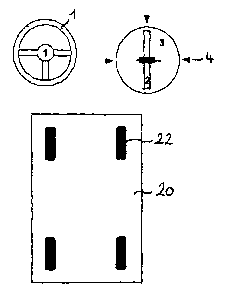
Figure 2 schematically shows the vehicle 20 with four wheels 22 separately
steerable by means of steering means which are not illustrated here in greater
detail. In accordance with the invention, any number of wheels 22 can be
steered
with the steering system of the invention. The intuitive steering in
accordance with
the invention is controlled by means of three operating elements. This is on
the
one hand the steering setpoint transmitter 1 in the form of a steering wheel.
Beside
the same, there is shown an operating element for shifting the steering line 2
in the
form of a sliding potentiometer. The same is mounted in a rotatable disk 3,
which
is the operating element for continuously controlling the main direction of
the
vehicle. This rotatable mounting plate includes an angle transmitter (not
shown in
the drawing) performing an absolute measurement, which detects the position of
this device. There are provided lock-in positions, which are not shown in
detail
here, but are indicated by the arrows 4, and to which corresponds the
preselection
of the basic setting at 00, i.e. for driving straight ahead in longitudinal
direction, at
+90 , i.e. for driving straight ahead in transverse direction to the right,
and at -90 ,
i.e. for driving straight ahead in transverse direction to the left. The
respective
operation of the individual operating elements will be explained with
reference to
the following Figures.
In the representation as shown in Figure 3, cornering of the vehicle 20 is
preset by
means of the steering wheel 1. As long as the operating elements 3 and 4
remain
in their neutral position, an all-wheel steering is obtained, which has a
steering line
24 in the middle of the vehicle 20. In contrast to changing the other
operating
elements, the steering wheel 1 can be used for changing the orientation of the
vehicle, i.e. the vehicle can be turned. Rotating the steering wheel shifts
the
steering pole 26 along the steering line and produces cornering with the
actual
steering pole as center of the curve. All steered axles of the individually
steerable
wheels are aligned with this steering pole 26. When the steering wheel is
=
CA 02526958 2005-11-15
- 6 -
positioned straight ahead, the steering pole is infinitely far away from the
vehicle.
With increasing steering angle, the steering pole approaches the vehicle more
and
more from the right or from the left, depending on the steering direction.
In Figure 4, the steering wheel 1 and the operating element for continuously
shifting the steering line 24 are varied, the steering geometry of the vehicle
being
influenced by the shift in the steering line, in that the steering line 24 of
the
steering can be shifted forward and backward, and in accordance with the
present
invention shifting is effected in an infinitely variable way by adjusting the
operating
element 2. When the steering line 24 now is shifted forward, as shown in
Figure 4,
the influence of the front wheels on the steering is decreasing more and more.
With a maximum shift in forward direction, i.e. the limit value, which is
exactly
shown in Figure 4, the front wheels are rigid. With this setting, the vehicle
can for
instance easily be driven forward and into a narrow corridor, or can stably be
driven rearward at high speed.
When the steering line is in the neutral position, as shown again in Figure 5,
an all-
wheel steering is obtained, in which the steering angles of the front and rear
wheels are symmetrical. With this setting, the smallest curve radius and thus
the
greatest maneuverability are achieved. With the setting as shown in Figure 5,
the
operating element for controlling the main direction 3 likewise still is in
the neutral
position. When the steering line now is shifted to the rear by means of the
operating element for continuously shifting the steering line 24, the
influence of the
rear wheels on the steering is decreasing more and more. With a maximum shift
to
the rear, as it is shown in Figure 6, the rear wheels are rigid. With this
setting, the
vehicle can stably be driven forward at high speed corresponding to a
passenger
car and can easily be driven rearward into a narrow corridor.
With reference to Figure 7, the control of the main direction can now be
explained
in detail. For controlling the main direction, the operating element for
continuously
controlling the main direction 3 is used. The adjustability of this rotatable
plate is
illustrated by means of the double arrow a. The respective position of the
plate 3,
as it is adjusted by the driver, is detectable by a non-illustrated angle
transmitter
performing an absolute measurement, as has already been described above. This
adjustable main direction is set with the steerable wheels 22, as is
illustrated by
means of the double arrows b directly in the vicinity of the wheels 22 in
Figure 7.
CA 02526958 2005-11-15
- 7 -
Figure 8 now illustrates by way of example the use of all three operating
elements,
i.e. the steering wheel 1, the operating element for continuously shifting the
steering line 2 and the operating element for continuously controlling the
main
direction of the vehicle 3. The adjustment of the main direction here
corresponds
to a rotation of the steering line 24 including the steering pole 26 about the
vehicle
center 28.