Note: Descriptions are shown in the official language in which they were submitted.
CA 02526999 2009-06-19
SKI EXERCISING AND TRAINING APPARATUS
Field of the Invention
The present invention relates to exercising apparatus for a user to simulate
the
motions, exertions and techniques involved in skiing, and for rehabilitation
that
simulates the range of motion and balance required in many sports, while
providing
modality for dynamic balance and functional rehabilitation, thereby increasing
the
user's strength and skill, and more particularly to improvements in such
apparatus.
Background of the Invention
Apparatus for use by skiers on which they may simulate the motions, exertions
and techniques required in skiing has been built and sold for several years.
In
particular U.S. Pat. No. 3,524,641 was issued to Robert J. Ossenkop on Aug.
18,
1970, for a device comprising a movable carriage on a set of rails. The
carriage of that
device is constrained in its movement on the rails by flexible members
attached to
both the carriage and to transverse members between the rails near each end of
the set
of rails, and a user can move the carriage from side to side on the rails to
simulate the
Wedeln or "parallel" technique of skiing.
U.S. Pat. No. 3,547,434 was issued to the same inventor on Dec. 15,1970.
This later patent is for a device similar to the first device, but comprising
a number of
1
CA 02526999 2005-11-24
WO 2004/105899 PCT/US2004/014585
improvements, such as movable footrests on the carriage whereby a user may
simulate
turning and edging techniques in addition to parallel skiing; and, in some
embodiments may also move the feet relative to one another.
The inventions referenced above each include a safety strap attached to a
transverse member between the parallel rails and to the carriage on the rails
in
addition to the flexible member by which the carriage is constrained to travel
on the
rails. The purpose of the safety strap is to provide for a situation in which
the
aforementioned flexible member might rupture on one side of the carriage,
providing
a sudden force urging the carriage to the side where the flexible member
remains
unruptured, which sudden force could dislodge a user and perhaps cause serious
injury. The safety strap in such instance provides a restoring force toward
the center
tending to lessen the amplitude of carriage displacement that might otherwise
occur.
In U.S. patent 4,743,014, to which this case is related, and by the same
inventor, an exerciser is disclosed having a pair of spaced-apart rails, a
platform for
riding on the rails, a first resilient element providing a first restoring
force on the
platform, and a second resilient element providing a second restoring force on
the
platform. The second resilient element has an adjustment element contacting
the
second resilient element in at least three points.
In the latter exerciser, the rails are held in a spaced-apart relationship by
a
brace element in the center, which is fastened to the rails by screw-type
fasteners, and
by transverse elements fastened at the ends of the rails. The transverse
elements at the
ends are tubular in form, and the rails pass through openings in the tubular
transverse
elements, fastening to a bracket internal to each tubular transverse element.
This
joining arrangement is illustrated by FIG. 1 A and FIG. 1B of the referenced
patent. As
shown in these figures rails 301 and 303 pass through holes 305 and 307
respectively
into tubular transverse element 309. Inside, the rails are fastened to a
bracket 311 by
screw fasteners 313 and 315. Rubber-like end caps 317 and 319 close the ends
of the
tubular transverse element after assembly and act as non-skid pads in contact
with the
floor in operation. The end caps are of molded rubber-like material, and disk-
like
pieces carrying designs and lettering are added for identification and
aesthetic effect.
This particular method of joining and spacing the rails has not proved
entirely
satisfactory in terms of cost and ease of assembly, and in terms of strength
and rigidity
2
CA 02526999 2009-06-19
of assembly, and the multiple-piece construction of the end caps has also
proved to be
relatively expensive.
In U.S. patent no. 6,569,064, to which the present application is related, a
ski-
exercising machine is provided comprising a set of at least two parallel rails
joined to
cross members at the ends, the cross members providing support on a horizontal
support surface, and joined to a central frame structure extending from the
horizontal
surface near the center to the rails, the rails extending from each cross
member at
each end upward at an acute angle with the horizontal rising to a maximum
height in
the center; a wheeled carriage riding on the rails; at least one articulated
footpad
mounted to the wheeled carriage; and a set of three power bands each anchored
at
both ends by a clamp to a bottom surface of the frame structure beneath the
wheeled
carriage, passing over separate roller sets, with one or more of the power
bands
anchored to the wheeled carriage and one or more passing over a roller
anchored to
the wheeled carriage.
Although related U.S. patents issued to the inventor address the above problem
and other problems related to construction and function of various components
of the
parent ski exerciser, there are still non-obvious improvements desired in
several areas
related to construction or assembly techniques, profile, materials, operation
and
longevity of the apparatus. For example, in U.S patent 5,147,257 (hereinafter
'257), in
Fig. 5A and 5B, a ski exerciser is illustrated both in an elevation view (Fig.
5A), and
in a plan view (overhead Fig. 5B). Arcuate rails 15 comprise tubing structures
having
a continuous arc or bow over their entire length.
Additionally, further non-obvious improvements are desired in several areas
related to tension adjustability of the power bands, band roller operation,
positioning
of individual footpads on the wheeled carriage, simulation of actual skiing
movements
and dynamics, as well as rehabilitation and versatility of the skiing
apparatus to
3
CA 02526999 2009-06-19
simulate range of motion and balance required in many sports other than
downhill
skiing. Still further improvements are desired in areas relating to safety
aspects of
apparatus to minimize the possibility of injury to the user.
It has been discovered partly through empirical methods that an even better
action may be simulated with rails shaped somewhat differently than in the
prior art.
Firstly, the arcuate portions of the parallel rails can be shortened, and the
straight
portions lengthened to provide more intensity in the simulation of the skiing
action.
3a
CA 02526999 2005-11-24
WO 2004/105899 PCT/US2004/014585
Secondly, the inventor has discovered that further adjustability of the power
bands, in
addition to footpad positioning, pivoting and sliding action, provide more
accurate
skiing motion simulation than the apparatus in the referenced prior art.
Fig. 5A in'257 illustrates roller assemblies housing rollers such as rollers
25
and 27 which are identical in size and construction with other illustrated
rollers which
make rolling contact with resilient members 23 and 59. The diameter of the
aforementioned rollers is disclosed as approximately 1 inch, and the rollers
are
generally cylindrical. It has been discovered that larger rollers, also
crowned have a
beneficial effect in smoother power band operation. The crowned rollers keep
the
belts better centered on the rollers.
The present inventor has also determined that improvements may be made in
the positioning of wheels for the wheeled carriage, and in the form of the
rails and
how the wheels interface to the rails.
Fig. 16 in '614 illustrates a ski exercising apparatus 301 according to an
embodiment of the present invention having an optional third power band
assembled
between the first, or outer power band, and the second, or inner, power band,
and a
pair of tensioning structures (303 and 304), each having a single roller
assembly
rotatably mounted to the tensioning structure such that consistent tension is
provided
to the wheeled carriage assembly given a specific range of motion of the
carriage
assembly.
What is clearly needed is a modularly enhanced ski-excising device that
provides further distinct advantages for the expanding field of users. Such an
improved device could provide further adjustability of power band tension, and
additional pivoting action for suspended footpad assemblies to provide a more
realistic simulation of skiing movements and dynamics in varying skiing
terrain.
What is also clearly needed is an improved method and apparatus enabling the
user to
quickly interchange footpad assemblies of a wheeled carriage assembly having
additional attachments for rehabilitation and selective body strengthening,
which
simulates the range of motion and balance required in many sports other than
downhill
skiing, accurately reproducing lateral movements required in most sports,
thereby
optimizing rehabilitation and helping to prevent injury to the user. Such an
improved
apparatus incorporates additional safety features, which further protect the
user from
injury during operation of the exercise apparatus.
4
CA 02526999 2010-06-18
Summary of the Invention
The present invention is directed to a ski exercising apparatus, comprising a
set of at least two parallel, partially arcuate rails joined to an underlying
frame
structure at opposite ends, the rails providing a track rising from each end,
a
wheeled carriage riding on the track, such that the carriage, in side-to-side
movement rises to a maximum height at the center of the track, and descends
from
the center to each side, at least one articulated footpad mounted to the
wheeled
carriage, a set of three power bands, and a pair of adjustment assemblies,
each
having a base attached to the underlying frame structure on each side of
center
and two rollers attached to each base. The apparatus is characterized in that
the
power bands are arranged concentrically, with an outer, an inner, and a middle
band, joined at one point each to the wheeled carriage and at least two points
each
to the underlying frame structure, and in that the attachment of the middle
power
band to the underlying frame structure is through the adjustment assemblies
and the
adjustment assemblies are removable and adjustable, independently, along the
underlying frame structure.
In a preferred embodiment, in each adjustment assembly, the middle power
band passes under one of the rollers and around the other. Also in a preferred
embodiment the roller which the middle band passes around can be fixed at any
one of at least three positions in the adjustment assembly, each position at a
different distance from the center of the apparatus, to adjust tension on the
middle
band.
In another aspect of the invention, in an adjustment assembly for mounting a
roller between two vertical walls attached to the base and spaced apart by a
first
distance, the roller for restraining and guiding a power band for a ski
exercising
apparatus having a wheeled carriage rolling on partially arcuate rails, the
power
band affixed to the carriage and passing around a roller in the mechanism, an
improved roller axle is provided, comprising a first element including an axle
portion
5
CA 02526999 2010-06-18
of a first diameter and a length equal to the first distance, having a
concentric
threaded hole on a first end, an engagement portion concentric with the axle
portion, of a length equal to a thickness of one of the walls, and larger in
diameter
than the axle portion to match a diameter of a hole in the one of the walls,
and a
head portion concentric with the axle portion and larger in diameter than the
hole,
for inserting through the hole and extending the axle portion between the two
walls,
and a second element including a head portion equivalent to the head portion
of the
first element and an engagement portion equivalent to the engagement portion
of
the first element, and also including a male threaded portion extending from
the
engagement portion for mating with the concentric threaded hole of the first
element, the second element for inserting through a hole in the other of the
two
walls, equivalent to the hole in the first of the two walls, and for engaging
with the
first element to form an axis for a roller to be mounted between the walls,
and also
for stabilizing and strengthening the assembly.
In yet another preferred embodiment the adjustment assemblies each
include a slot at opposing ends of the base for engaging matching upwardly
extending portions of the frame structure extending the length of the frame
structure, allowing the user to independently slide the adjustment assemblies
along
the upwardly extending portions of the frame structure in various
predetermined
attachment locations. This enables still further adjustability of the location
of a
tension point of the middle band prior to fixing the assemblies to the frame
structure. After fixing, a bottom surface of the base securely rests upon an
upper
surface of a bottom of the frame structure between the extending portions of
the
frame structure enabling a more secure attachment of the adjustment assemblies
to
the bottom central frame structure of the ski apparatus.
6
CA 02526999 2010-06-18
Brief Description of the Drawing Figures
Fig. 1A is an elevation view of a frame structure of a ski-exercising device
according to an embodiment of the present invention.
Fig. 1 B is a cross section taken along line 1 B-1 B of Fig. 1 A.
Fig. 2 is a plan view of the frame structure of Fig. 1 with added components
illustrated according to an embodiment of the present invention.
Fig. 3 is a perspective view of a center portion of the structure of Fig. 1
with
covering components removed.
Fig. 4 is a perspective view of a wheeled carriage-assembly shown without an
upper carriage according to an embodiment of the present invention.
Fig. 5 is a perspective view of an upper carriage-assembly supporting a
suspended footpad mounted according to an embodiment of the present invention.
Fig. 6 is an elevation view of a wheeled carriage-assembly and mounted foot
platforms according to an embodiment of the present invention.
Fig. 7A is perspective broken-view of a portion of a rail, transverse end
member, and end-cap according to an embodiment of the present invention.
Fig. 7B is an elevation view of an end-side of the end cap of Fig. 7A.
Fig. 7C is an elevation view of a bottom-side of the end cap of Fig. 7B.
Fig. 8 is a perspective view illustrating various components of a quick-
release
roller assembly according to an embodiment of the present invention.
Fig. 9A is a plan view of an elongated footpad and carriage-assembly
according to an embodiment of the present invention.
Fig. 9B is an elevation view of the footpad and carriage assembly Fig. 9A.
Fig. 10 is an elevation view of the frame structure of Fig. 1 illustrating
roller-
band tensioning hardware according to an embodiment of the present invention.
7
CA 02526999 2010-06-18
Fig. 1 1A is a broken view of a potion of toothed rails and a toothed gear of
Fig. 10 according to an embodiment of the present invention.
Fig. 1 lB is an elevation view of the handle assembly of Fig. 10.
Fig. 11 C is an elevation view of the rail-guide bracket of Fig. 10.
Fig. 11D is a right-side view of the bracket of Fig. 11 C.
Fig. 11 E is a broken view of a portion of the bottom toothed-rail, roller,
and
bracketed roller-mount of Fig. 10.
Fig. 11F is a broken view of the bottom toothed-rail, roller, and bracketed
roller-mount of Fig. 10 as seen from an overhead vantage.
Fig. 12 is a perspective view of an adjustable double footpad module
according to an embodiment of the preset invention.
Fig. 13A is a plan view and Fig. 13 B is a side view of a slotted base-plate
according to an embodiment of the present invention.
Fig. 13C is an end-view of the slotted cam-rod of Fig. 12.
Fig. 14 is a cross-sectional view of a main wheel, a keeper wheel, and a semi-
arcuate rail according to an alternate embodiment of the present invention.
Fig. 15 is a cross section of an integral captive rail and wheel arrangement
in
an embodiment of the present invention.
Fig. 16 is an elevation view of a ski-exercising device illustrating an
optional
third power band according to another embodiment of the present invention.
Fig. 17 is an elevation view of a ski-exercise device illustrating adjustable
tensioning structures for an optional third power band according to an
embodiment of
the present invention.
Fig. 18A is an elevation view of an adjustable tensioning structure of Fig.
17,
and a roller axle.
8
CA 02526999 2010-06-18
Fig. 18B is an elevation end view of the adjustable tensioning structure and
roller axle of Fig. 18A and a roller axle nut.
Fig. 19 is an elevation view of a frame structure of the ski-exercising device
of
Fig. 17.
Fig. 20A is a top view of an adjustable mounting plate according to an
embodiment of the present invention.
Fig. 20B is a section view of the mounting plate of Fig. 20A taken along
section line 20B-20B.
Fig. 21A is a top view of a sliding attachment plate according to an
embodiment of the present invention.
Fig. 21B is a section view of the sliding attachment plate of Fig. 21A taken
along section line 21B-21B.
Fig. 22 is a top view of the mounting plate of Fig. 20A and a pair of sliding
attachment plates of Fig. 21A according to an embodiment of the present
invention.
Fig. 23 is an elevation view of a suspended footpad assembly and the sliding
attachment plate of Fig. 21A.
Fig. 24 is an elevation view of the footpad assembly and attachment plate of
Fig. 23 and the mounting plate of Fig. 20A attached to a carriage assembly
according
to an embodiment of the present invention.
Fig. 25A is a top view of the mounting plate and attachment plates of Fig. 22,
a pair of suspended footpad assemblies of Fig. 24 and a carriage assembly
according
to an embodiment of the present invention.
Fig. 25B is an elevation view of the mounting plate, attachment plates,
suspended footpad assemblies and carriage assembly of Fig. 25A.
Fig. 26A is an elevation view of an upper body conditioner (UBC) elevated
grip according to an embodiment of the present invention.
9
CA 02526999 2010-06-18
Fig. 26B is a top view of the UBC elevated grip of Fig. 26A.
Fig. 27A is a top view of a UBC lower grip according to an embodiment of the
present invention.
Fig. 27B is a side elevation view of the lower grip shown in Fig. 27A.
Fig. 28A is a top view of the mounting plate, attachment plates and carriage
of
Fig. 25A, and a pair of UBC elevated grips and a pair of UBC lower grips
affixed to
the attachment plates according to an embodiment of the present invention.
Fig. 28B is an elevation side view of the mounting plate, attachment plates,
carriage, UBC elevated grips and UBC lower grips of Fig. 28A.
Fig. 29A is a top view of a footpad pivot base according to an embodiment of
the present invention.
Fig. 29B is an elevation side view of the footpad pivot base of Fig. 29A.
Fig. 29C is an elevation end view of the footpad pivot base of Fig. 29A.
Fig. 30A is an elevation end view of a footpad pivot support structure
according to an embodiment of the present invention.
Fig. 30B is an elevation side view of the footpad pivot support structure of
Fig.
30A.
Fig. 30C is a top view of the footpad pivot support structure of Fig. 30A.
Fig. 31A is a top view of a pivot roller base assembly according to an
embodiment of the present invention.
Fig. 31 B is an elevation end view of the pivot roller base assembly of Fig.
31A.
Fig. 31C is an elevation side view of the pivot roller base assembly of Fig.
31A.
Fig. 32A is an elevation view of the footpad pivot base of Fig. 29B, footpad
pivot support structure of Fig. 30B and the pivot roller base assembly of Fig.
31B
CA 02526999 2010-06-18
according to an embodiment of the present invention.
Fig. 32B is an elevation end view of the footpad pivot base, footpad pivot
support structure, and pivot roller base assembly of Fig. 32A.
Fig. 33A is an elevation view of a roller axle assembly according to an
embodiment of the present invention.
Fig. 33B is an elevation end view of the roller axle assembly of Fig. 33A.
Fig. 34 is an elevation side view of a cable-securing axle according to an
embodiment of the present invention.
Fig. 35 is an elevation side view of an optical sensor assembly according to
an
embodiment of the present invention.
Fig. 36 is an elevation view of the frame structure of Fig. 17, the carriage
assembly, mounting plate, attachment plate, and suspended footpad assemblies
of Fig.
25A, and sensor system according to an embodiment of the present invention.
Fig. 37 is a top view of the carriage assembly, mounting plate, attachment
plate, suspended footpad assemblies, and sensor system of Fig. 37.
Fig. 38 is a perspective view of an adjustable flag assembly according to an
embodiment of the present invention.
Fig. 39 is an elevation view of the carriage assembly, mounting plate,
attachment plate, suspended footpad assemblies, and sensor system of Fig. 38
incorporating a pair of flag assemblies of Fig. 36 according to an embodiment
of the
present invention.
Fig. 40 is an elevation view of the carriage assembly, mounting plate,
attachment plate, suspended footpad assemblies, sensor system and flag
assemblies of
Fig. 39, incorporating a progressive resistance cord system according to an
embodiment of the present invention.
11
CA 02526999 2010-06-18
Description of the Preferred Embodiments
It is the object of the present invention to provide a ski exercising
apparatus
similar to that apparatus covered in cross-related documents above that is
modularly
enhanced such that, among other improvements, changing applications on the
apparatus may be performed with minimal effort. It is also an object of the
present
invention that the above apparatus be generally and innovatively improved to
accomplish a goal of maintaining a light weight while increasing strength and
durability of the apparatus. A fin-ther object of the present invention is to
provide
such an apparatus as described above having a lower profile, improved safety
features,
and having fewer assembly parts with which to contend. It is also an object of
the
present invention to more accurately simulate the motions and dynamics of
skiing in
terrain, which varies in steepness, bumpiness and other aspects of the
terrain, as well
as skiing in such terrain at varying speeds and aggressiveness. Yet another
object of
the present invention is to provide a ski apparatus having a monitoring system
integrated therein which provides the user with information pertaining to the
workout
in order to enable the user to best utilize the apparatus and maximize
effectiveness of
the workout or training. Such information may include elapsed time from start
to
finish of the workout, goal determination and accomplishment, energy or
calories
expended by the user, speed of turns, side travel distance of the wheeled
carriage, and
so on. It is still further an object of the present invention to provide such
a ski
exercising apparatus which, when used with special attachments and other new
and
novel apparatus, becomes a versatile rehabilitation and training tool that
simulates the
range of motion and balance required in many sports other than downhill
skiing. Such
an apparatus is enabled for selectively stretching, strengthening or
rehabilitating
12
CA 02526999 2010-06-18
specific areas of the body, core stabilization, balance training and many
other aspects
of selected training and exercise. Such an apparatus and system accurately
reproduces
the lateral movements required in most sports, thereby optimizing
rehabilitation and
helping to prevent injury to the user. Such a ski-exercising apparatus is
described in
enabling detail below.
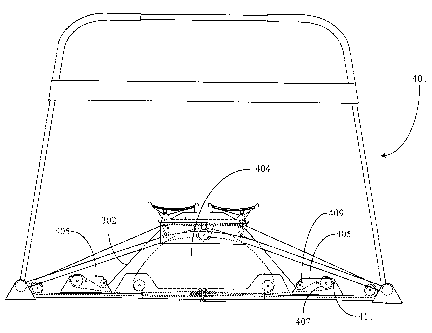
Fig. 1 is an elevation view of a frame structure 11 of a ski-exercising
apparatus
9 according to an embodiment of the present invention. Apparatus 9 is provided
having a generally similar frame-architecture to previously described
exercisers
disclosed in related U.S. patents issued to the inventor except for novel
improvements
that are described below. For the purpose of clarification, only a frame
structure 11 of
apparatus 9 is described in this embodiment. Additional components not seen
here are
described later in this specification.
In a preferred embodiment of the present invention, frame structure 11
comprises a pair of semi-arcuate rails 22 that are held parallel to each other
and are
affixed at either end of each rail to a pair of transverse end-members 27. As
this is an
elevation view, only one of the pair of rails is seen. The spacing and
parallelism is
seen in plan view Fig. 2. This arrangement of rails 22 affixed to members 27
forms
the basic frame-structure 11 of apparatus 9. One notable difference between
semi-
arcuate rails 22 and the fully arcuate rails disclosed in related patents such
as rails 15
of U.S. Pat. 5,147,257, is as the respective descriptors imply. That is, as in
Fig. 1A,
rails 22 are arced only in their center portions 23 and illustrated by a
dimensional
notation E. The dimension lines associated with portion 23 mark the locations
where
the arced portion of each rail 22 ends at positions sharing an equal distance
from a
theoretical vertical center of rails 22.
The total distance E in a preferred embodiment is approximately 26 inches,
defined as that portion of each rail 22 that is arced. The stated arc of
arcuate portion
13
CA 02526999 2010-06-18
23 has a radius of approximately 76 inches although a somewhat higher or lower
radius may be used in other embodiments. Non-arcuate portions of rails 22 are
witnessed by element numbers 19 and 21 on the left and right side of apparatus
9 as
seen in this view. The lengths (taken horizontally) for rail portions 19 and
21 are
approximately 15 inches respectively. Rail portions 19 and 21 are
substantially
straight from their junctures with arcuate portion 23. The dimensions cited
above are
intended to be approximate only. When including an approximate 2.36-inch (6cm)
diameter for each transverse member 27, the approximate overall length of
frame
structure 11 is about 61 inches. Semi-arcuate rails 22 may be manufactured
from
heavy-gauge steel tubing as described in U.S. Pat. 5,147,257. In one
embodiment,
rails 22 may be made of extruded steel or aluminum bars rather than steel
tubing, and
rails may be solid or hollow in different embodiments. Such rails may often
also be
formed in a forming die to manufacture tracks.
Solid aluminum bars may in some circumstances offer more strength than steel
tubing in terms of flexing or bending while retaining a lightweight
characteristic.
Moreover, such bars may be extruded to comply with varied shapes as may be
desired,
and may also be produced in hollow configurations. In this particular
embodiment,
rails 22 are solid and round in cross-section (rods). The semi-arcuate design
and solid
structure of rails 22 adds considerable strength and durability causing less
flex when
rails are in use. It is not specifically required that rails 22 be of round
cross-section in
order to practice the present invention. The inventor intends merely that
keeping a
round cross-section consistent with previously used steel tubing is consistent
with
conventional wheels used on wheeled-carriage assemblies such as carriage 11
described in U.S. Pat. 5,147,257.
14
CA 02526999 2010-06-18
In another embodiment, rails 22 may be extruded and then die-tbrmed to a
shape that may conform to an alternate wheel design. Such an embodiment is
described later in this specification. The size of rails 22 is approximately
2.5 cm. (1-
inch) in diameter as is consistent with previous related embodiments. However,
this
should not be construed as a limitation in diameter but only a preference in
balancing
durability with lightweight characteristics. Other diameters for rails 22 are
plausible.
Transverse members used in an embodiment where rails are aluminum will also be
made of aluminum tubing to facilitate welding. However, where rails are steel
tubing
or rods, transverse members will typically be manufactured from steel tubing.
A
durable polymer coating is applied to all visible parts and surfaces of
apparatus 9 in
order to provide a resistance to corrosion and for appearance purposes.
The straight portions of rails 22 to each side of arcuate portion 23 provide a
carriage movement in operation that more nearly simulates an actual skiing
experience, as has been testified to by users of the apparatus.
In a preferred embodiment of the present invention, rails 22 are welded to
transverse members 27 to form a one-piece truss-frame insuring long life and
durability along with ease of assembly of associated elements. However, many
fastening methods are known and practiced in the art and could also be used to
affix
rails 22 to transverse members 27. The frame structure 11 of apparatus 9 also
comprises belt guides 24 located in a substantially centered and parallel
position in-
between rails 22 and welded, at opposite ends, to transverse members 27 and to
a
support frame member 31 supporting the rails in the centered arcuate portion.
Belt
guides 24 allow a power band such as element 23 of Fig. 5A of '257 to be
separated
from the floor or carpet during operation, thus contributing to longer life
and sparing
wear and discoloration of the floor or carpet. A belt guide of the type
disclosed herein
CA 02526999 2010-06-18
has not been previously taught. A pair of raised ribs 26 running the length of
belt
guides 24 on each side of member 31 are provided and adapted to allow a power
band
to avoid contact with the bottom of belt guide 24 further reducing wear and
noise.
Support member 31 is provided for the purpose of lending additional support
to the frame structure 11 of apparatus 9, and for housing mechanisms
associated with
operation of the exerciser. A structure of the same name is illustrated in
Fig. 5A
(element 55) of '257 and member 31 is analogous to that member, but improved
in
function. For example, support member 31 as illustrated herein, is longer in
length
than the aforementioned member 55 thereby supporting more area of rails 22.
Support
member 31 may be provided as one piece or as a plurality of components welded
together such that one single piece is formed. Support member 31 is made wider
than
previously disclosed support members such that it maybe welded in some
embodiments to the outside edges of rails 22 instead of having rail-inserted
tabs as
described with member 55 of Fig. 5A in'257. Welding support member 31 to the
outside edges of rails 22 increases the strength and durability of frame
structure 11,
and allows further improvements described more fully below.
Support member 31 is further welded to belt guides 24 as previously
described, effectively adding these components to frame structure 11 so as to
form a
single contiguous and integral frame, thereby lending strength, durability,
and
eliminating assembly requirements. Also welded to support member 31 is a
tension-
adjustment structure 25, Structure 25 in this embodiment is a u-shaped
structure
welded to the bottom of member 31 such that two vertical planes are presented,
one
on each side of the power band path, with holes for positioning rollers for
adjustment
of power band tension. The length of structure 25 is such that it extends
beyond each
side of member 31, as shown, and guides 24 weld to structure 25. In this
manner
structure 25 becomes a part of the overall welded structure 11 adding durable
strength
to the structure as a whole. Additionally, two roller brackets 34 are
illustrated,
16
CA 02526999 2010-06-18
housing rollers 35 in this embodiment, and these are also welded to transverse
members 27 and to belt guide 24, and are part of frame structure 11 of
apparatus 9.
Much assembly is avoided and much durability and strength is added by
providing a
multi-component but single piece welded frame architecture for apparatus 9 as
will
readily be appreciated by one with skill in the art.
A protective resilient, non-skid pad 29 is provided and mounted in a position
beneath support member 31. Pad 29 may be affixed to support member 31 by
gluing,
fastening such as by recessed screws, or other known methods. The purpose of
pad 29
is to protect floor coverings from contact with support member 31 so as to
avoid
scratching and the like, as well as to keep apparatus 9 from skidding when in
use.
This pad also provides service in reducing vibration and noise. Four resilient
end-
caps 17 are provided to cover the ends of transverse members 27. End-caps 17
provide non-skid contacts between apparatus 9 and a floor or other support
surface.
Another component illustrated in this embodiment is an optional support
frame 14 for a novice user to hold on to for stabilization while using
apparatus 9.
Support frame 14, termed an Assistant Coach by the inventor, comprises a
tubing
structure 16, a cross member 13, and padded gripping areas 15. Tubing
structure 16
may be a one-piece tube bent to form structure 16, or a combination of
straight and
curved pieces, which are provided and assembled to form structure 16. Steel or
another form of durable tubing of an approximate 1-inch diameter may be used.
Other
sizes are also useful.
Gripping areas 15 (one on each side) may be formed of a durable synthetic
material such as a dense polyurethane foam, vinyl, or other materials known
for
providing a gripping surface to tube handles and the like that are common in
the field
of exercise equipment. In one embodiment, gripping areas 15 may be removed
such
17
CA 02526999 2010-06-18
as by conventional methods known in the art. In another embodiment, gripping
areas
15 are permanent such as sprayed on or glued. Cross member 13 may be
manufactured from a durable plastic or other material such as sheet steel or
aluminum.
Cross member 13 may in some embodiments be welded to tube structure 16. In
other
embodiments, other known fastening techniques such as nut and bolt, or metal
screws
may be used. There are many possibilities.
Support frame 14 is welded or fastened to two transverse members similar to
members 27 but not seen here because of the direction of view (see Fig. 2
element
49). Such members act as an optional extension to transverse members 27 at the
rear
of apparatus 9. By removing resilient end-caps 17 from the rear or front of
apparatus
9, support structure 14 may be connected to the transverse members 27 of frame
structure 11. In some embodiments an additional interface and support element
is
added between elements 11 and 27.
Fig. 2 is a plan view of the frame structure 11 of apparatus 9 of Fig. 1 with
added components illustrated according to an embodiment of the present
invention.
As previously described, support frame 14 is an optional extension to frame
structure
11 of apparatus 9. A user wishing to install support frame 14 simply removes
two end
caps 17 from the rear of frame structure 11 and connects the support frame.
The point
of connection for the two structures is illustrated as line 51 at either end
of device 9.
Transverse members 49 each have a fitting end 52 that is of a smaller diameter
over a suitable length than the inside diameter of transverse members 27. The
diameter is small enough so that transverse members 49 may be easily fit into
transverse members 27 such that when fully inserted lines 51 are formed
representing
the joining of each structure. Circular shims (not shown) that are once split
through
along a longitudinal edge of each shim are used to obtain a snug fit between
transverse
members 27 and 49. Such shimming methods are well known in the art. Setscrews
18
CA 02526999 2010-06-18
(not shown) or other known types of fasteners may be used to secure the
installation.
As seen in this overhead view, power band guides 24 extend from each end of
the structure (members 27) toward the center and are welded at opposite ends
to
structure 25, which in turn welds to member 31 (Fig. 1A). Roller brackets 34
are
welded to transverse members 27 and to belt guide 24 as previously described
above.
Two rollers 47 and 45 are illustrated as mounted to tensioning structure 25.
Rollers
47 and 48 are provided and adapted to support a central power band 46.
Likewise, a
power band 43 is supported by rollers 35 and 37. An additional roller (not
shown) is
provided for further support of power band 46 and is centered in-line and in-
between
rollers 47 and 45 at a raised position such that a triangular configuration of
the three
rollers is formed. Power bands 43 and 46 are manufactured of a proprietary
rubber
compound or similar material as described in U.S. Pat. 5,147,257.
Aforementioned
rollers such as rollers 35 and 37 are manufactured of polypropylene or similar
material
in a preferred embodiment.
Tension-adjustment structure 25 acts as a rigid mounting location for rollers
47 and 45. A plurality of openings provided in collinear arrangement through
opposite-facing sides of structure 25 are used to mount rollers 47 and 45 via
a quick-
release pin-and-shaft mounting technique that is described in detail later in
this
specification. By removing and re-mounting rollers in different positions on
structure
25, tension adjustments to power band 46 may be affected.
A wheeled lower carriage assembly indicated as element 33 in Fig. 2, but best
seen in Fig. 4, rides on rails 22. This carriage is described in further
detail below with
reference to Fig. 4. Foot platforms 39 and 41 are mounted to an upper platform
unit
89, which in turn mounts to the lower wheeled carriage assembly by fasteners
53. The
arrangement of an upper platform for footpads mounting as a unit to a lower
wheeled
carriage allows different footpad arrangements to be quickly and easily traded
on a
standard wheeled carriage.
19
CA 02526999 2010-06-18
Center fastener 54 is not used when installing and removing upper foot
platforms, because it is a mounting fastener for a power-band roller beneath
carriage
33. A clearance hole is provided in the upper platform for this fastener.
Foot platforms 39 and 41, in the arrangement shown, provide a parallel skiing
simulation that is one option for mode of operation with apparatus 9. By
swapping
upper platforms with different foot interface arrangements the overall
apparatus can
be quickly adapted to other applications, as will be clearer with following
description.
In the embodiment shown, foot platforms 39 and 41 each have a footpad
surface thereon. Footpad surface 38 is affixed to platform 39, and footpad
surface 42
is affixed to platform 41. Footpad surfaces 38 and 42 are preferably made of a
non-
skid durable rubber material. Surfaces 38 and 42 may be installed using an
adhesive,
or other known methods such as screw fasteners or the like. Similarly, other
materials
may be used instead of rubber as long as a non-skid effect is maintained.
Rollers 35, 37, 47, 45, and the previously described roller (not shown) that
completes a triangular configuration with rollers 47 and 45 are now
significantly
larger in diameter than rollers previously disclosed in related applications.
Whereas
previously disclosed rollers were described as having about a 1-inch (2.5 cm)
diameter, the rollers of the present invention have substantially a 2-inch
(5cm)
diameter and are crowned. That is, the rollers are somewhat curved on the
outer
surface that meets the power band, so there is a marginally larger diameter at
the
center plane of the roller than at the roller edges. This improvement in
design ensures
that the power bands always remain centered on the rollers, which obviates
contact
with roller brackets and the like, reducing frictional wear to the power
bands, and
leads to smoother and quieter operation of apparatus 9.
Fig. 3 is a perspective view of the center portion of frame structure 11 of
Fig. 1
with covering components removed to show the elements beneath. As previously
described, support member 31 is welded to rails 22. In this example, a
plurality of
CA 02526999 2010-06-18
individual welds 55 is placed symmetrically along the length of support member
31.
There are three welds 55 shown in this example, however, there may be more or
fewer
such welds without departing from the spirit and scope of the present
invention. In
one embodiment, a continuous weld may run the entire length of support member
31.
Also in this example, welds 55 are illustrated as being placed from the
outside edges
21
CA 02526999 2010-06-18
trear-edge welds not visible) of support member 31 to the outside of rails 22.
There
are many possibilities regarding number of and location of welds 55.
Tensioning structures 25, as described with reference to Figs. 1 and 2, are
welded to belt guides 24 and to support member 31. Brackets 25 are shown with
rollers 47 and 45 mounted thereon. A suitable thickness for the material used
to
manufacture support member 31 and belt guide 24 is about 3mm. or 1/8 of an
inch. In
one embodiment of the present invention, aircraft quality aluminum may replace
sheet
steel for such components where possible. Using high quality aluminum instead
of
materials such as steel cited in related applications helps to strengthen
frame structure
11 as well as to reduce weight.
Yet another marked improvement over the prior art is in the method of
clamping the ends of power bands. In related documents it is described that
the
central resilient element has it's ends clamped at one location while a second
resilient
element has its ends clamped at locations on either side of the central clamp.
Therefore three clamping locations exist for securing the free ends of power
bands. In
this example, only one clamping location 57 is required. Clamp 57 secures both
the
ends of power band 43 and those of power band 46 of Fig. 2. This method
reduces
work-steps required to install power bands. A single clamping location also
ads
considerable safety in that only one clamp must be checked for integrity
therefore
lessening the possibility of error in set-up. In this particular example,
clamp 57 is a
bar clamp utilizing two standard hex-head nuts and bolts to effect tightening.
Fig. 3 also illustrates the positioning of rollers 45 and 47 in structures 25.
The
position of the rollers in this embodiment can be changed into any other of
the holes
in the sides of structures 25 to adjust the tension on the inner power band.
Fig. 4 is a perspective view of wheeled carriage-assembly 33 shown without
an upper foot platform 89 according to an embodiment of the present invention.
As
22
CA 02526999 2010-06-18
disclosed in related applications such as U.S.Pat. 5,147,257, for example,
there are
four main weight-bearing wheels that are mounted to the carriage body and
adapted to
make contact on the upper surfaces of rails 22 such that the carriage assembly
may
ride side-to-side on the rails as urged by a user. The wheels are
approximately 2cm
wide and are machined using an ultra high molecular weight (UHMW) long-chain
polymer material as described in 5,147,257. A standard button-head shoulder-
bolt
(not shown) forms the shaft of each wheel. Ball bearings, washers, a lock
washer, and
a castle nut complete the assembly components for mounting wheels to the
carnage
body as described in 5,147,257.
As in '257, there are four main wheels that ride on upper surfaces of rails
22.
Two are visible in this embodiment and are represented by element numbers 67
and
68. The remaining two main wheels are located toward the rear portion of
carriage
assembly 33 and are therefore hidden from view by carriage body 70, and are
not
represented in Fig. 4 to avoid unnecessary detail. These main wheels are
mounted
rotationally to carriage body 70.
Wheels 67 and 68 in a preferred embodiment are mounted at an approximate
12 degree angle from vertical with the angle toward the space in-between rails
22 such
that they make contact with a more inwardly surface of each rail. The rolling
surface
of each wheel is concave such that the radius across the width of each wheel
substantially matches the cross-sectional radius of rails 22. Wheels 67 and 68
as well
as two main wheels that are not visible here are mounted through provided
openings
strategically located on carriage body 70.
In this embodiment, an additional set of four keeper wheels is provided of
which two wheels 71 and 69 are visible in this view. Two other keeper wheels
are
located toward the rear of carriage assembly 33 and are hidden in this view by
carriage
body 70. Components forming the shaft and mounting hardware for keeper- wheels
71 and 69 are the same as those already described for wheels 67 and 68.
23
CA 02526999 2010-06-18
Keeper wheel 71 and 69 are strategically located beneath rails 22 at angled
positions that are inverted from the angled positions of main wheels 67 and
68, and
directly below weight-bearing wheels. Two angled mounting brackets 75 and 73
are
provided and adapted to secure keeper wheels 71 and 69 by being also mounted
to
upper wheels 67 and 68. Wheels at the rear of carriage assembly 33 (not shown)
are
similarly secured as brackets 75 and 73 run the entire length of carriage
assembly 33.
In this embodiment brackets 73 and 75 are secured to the upper wheels and the
lower wheels, so the lower keeper wheels are positioned by the upper wheels,
which
are mounted to the carriage body. In other embodiments brackets 73 and 75 may
extend further upward and be fastened to the underside of the carriage, such
as by
rivets or welding. The brackets may, for example, be fastened by any
convention
joining means. Angled mounting-brackets 75 and 73 assume an inclusive angle of
approximately 140 degrees such that each wing is substantially parallel to
desired
wheel positions when mounted. Ideally, carriage assembly 33 will remain
resident on
rails 22 when changing applications. This will allow for interchangeability of
pre-
assembled modules that are complete with selected foot platforms mounted.
Upper
platforms such as platform 89 of Fig. 2 may vary in physical appearance
depending on
the application; however, identical fastening locations allow
interchangeability with
carriage assemblies such as carriage assembly 33.
There are yet additional improvements made to assembly 33 over the prior art.
One such improvement is the provision of two clamping locations 63a and 65a
located
on the under-surface of carriage body 70 for the outer power band. A clamp bar
63 is
illustrated as one of two such clamp bars that are used to secure resilient
element 43.
A second clamp bar for clamping location 65a is not shown, but may be assumed
to be
24
CA 02526999 2010-06-18
present. Previous embodiments disclosed in related documents describe only one
clamping location located directly beneath the center of the carriage
assembly. An
advantage of having power band 43 clamped in two locations is that noise
caused by a
resilient element flapping against the underside of the carriage body is
eliminated, and
the carriage is stabilized even further.
Roller 59 is a third roller previously described to form a triangular
configuration of rollers to support power band 46 of Fig. 2. Like all rollers
described
in this specification, roller 59 is crowned for the purpose of guiding
resilient member
46 such that it remains centered on the rollers.
In this embodiment, roller 59 assumes a position much nearer in proximity to
the underside of carriage body 70 than in the cross-referenced patents. This
is due in
part to the larger diameter (2 inch) attributed to rollers of the present
invention as
opposed to previously disclosed 1 inch diameter rollers in related documents.
In
addition, roller 59 is simply mounted in a position that is nearer the
underside of
carriage body 70 by means of a roller bracket 61. This is done to reduce wear
caused
by resilient members rubbing and slapping against each other, and also, to
reduce
associated noise, The clearance is carefully designed as well so that, as the
roller
carriage moves to each side and back on the rails, the slack portion of the
outer power
band is carried to the side in the direction of carriage motion, which also
reduces noise
and sudden engagement.
It will be apparent to one with skill in the art that there are other possible
wheel arrangements that may be used with carriage assembly 33 than the one
illustrated herein without departing from the spirit and scope of the present
invention.
For example, the tilt angle of main and keeper wheels may be more or less than
20
degrees as mentioned in this embodiment. There may also be more or fewer main
and
or keeper wheels than is illustrated here.
CA 02526999 2010-06-18
In one embodiment, independent wheel pairs comprising one main wheel and
an associated keeper wheel may be bracketed independently such that there are
four
independently movable wheel sets.
Fig. 5 is a perspective view of an upper platform assembly 90 supporting a
suspended footpad 79 mounted to a carriage assembly 33 (wheels and brackets
not
shown) according to an embodiment of the present invention.
In this example, a single suspended footpad 79 is provided and adapted to be
pivotally suspended over upper platform assembly 90, termed a cradle in
related U.S.
Pat. 5,020,793, by means of two pivot points 85 and 87. Each pivot point 85
and 87,
in a preferred embodiment, comprises a journal bearing, a spacer bushing, and
a
threaded stud with suitable lock washers and a nut fastener. There are
equivalent ways
known in the art to accomplish such a pivot. A suitable rubber cover is
provided and
adapted to fit over pivot points 85 and 87 to protect components from
corrosion and
general exposure. Pivot points 85 and 87 are arraigned in collinear fashion on
opposite facing support wings represented by element number 81. The pivots are
fixedly mounted in vertical structures 83, which are a part of the platform
that mounts
to carriage 33. As described in U.S. Pat. 5,020,793, footpad 79 may swing
freely
about pivot points 85 and 87 as illustrated by double arcs that represent
direction of
swing.
The general application illustrated in this example is as stated in the
aforementioned related document whereas a user places only one foot in footpad
79
after it is installed on apparatus 9 of Fig. 1. By traversing back and forth
over rails 22
of Fig. 1, he or she experiences a benefit of simulated edging. As the length
of
traversing approaches maximum length of rails 22, footpad 79 pivots maximally
about
pivot ends 85 and 87.
Also noted herein is a no-skid surface 93 provided in the same fashion as
previously disclosed in Fig. 2 (elements 38 and 42). The fasteners for
mounting the
upper platform to carriage 33 are not seen in this view, but are the same as
previously
described for upper platforms in this disclosure.
26
CA 02526999 2010-06-18
According to a preferred embodiment of the present invention, footpad 79 with
upper platform assembly 90 may be removed as one unit from and installed as
one
unit onto any wheeled carriage- assembly having suitable mounting locations.
In this
way, a carriage assembly such as assembly 33 of Fig. 2 may be kept resident on
apparatus 9 of Fig. 2 with the loosening, removing, and re-tightening of only
two hex-
head nuts being required to change applications. This method reflects the
modular
nature of accessories such as footpad 79 mounted to upper platforms according
to a
preferred embodiment. Loosening and tightening bolts may be performed with the
aid
of a convenient T-handle socket tool (not shown) adapted to fit hex-head nuts
53. In a
preferred embodiment, all hex-head nuts subject to requirements of being
removed
and replaced due to the change of applications are the same size fitting the T-
handle
socket tool.
Carriage assembly 33 is shown in this example to illustrate orientation of
footpad 79. Carriage assembly 33 may be of a different overall length than
assembly
33 of Fig. 2. For example, a single footpad such as footpad 79 does not
require a
longer carriage assembly whereas a dual footpad installation would require a
longer
carriage assembly. In a preferred embodiment, carriage assembly 33 of Fig. 2
has a
maximum length such that all modular accessories are supported. That is not to
say,
however, that a modular accessory cannot have it's own carriage of a different
overall
length.
Carriage assembly 33 of Fig. 2 would preferably remain resident on rails 22 of
apparatus 9 (Fig.2), especially if keeper wheels are used as previously
described.
However, in an alternate embodiment where keeper wheels are not used, the
carriage
assembly illustrated in this example may have main wheels installed and may be
thought of as one module comprising assembly 33, upper platform 90, and
footpad 79.
In this embodiment, a roller such as roller 59 of Fig. 4 may be shared between
different applications. A quick release of roller 59 and removal of bar clamps
such as
27
CA 02526999 2010-06-18
clamp 63a of Fig. 4 will also allow removal and replacement of different
modules.
However, removing bar clamps entails much more effort on the part of a user.
The
added effort may be offset by the fact that different applications may require
different
tensioning adjustment with respect to a resilient member such as member 46 of
Fig. 2.
In addition to providing a single footpad in modular fashion as illustrated
herein, in a further embodiment an upper platform is provided having two such
single
28
CA 02526999 2010-06-18
suspended footpads may be mounted in spaced-apart fashion. In yet another
embodiment an upper platform assembly is provided wherein the spacing between
suspended footpads is adjustable, and the adjustment apparatus is described
further
below with reference to Fig. 12. Also, because of added keeper wheels such as
wheels
69 and 71 of Fig. 4, retaining a wheeled carriage on rails 22, footpad(s) 79
may be
significantly extended in length without the risk of tipping carriage 33 off
of rails
when in use.
Fig. 6 is an elevation view of wheeled carriage-assembly 33, upper platform
89, and mounted foot platforms 39 and 41 of Fig. 2 according to an embodiment
of
the present invention. Part of the upper carriage walls are broken out in this
figure for
the purpose of enabling a view of inner components, and the bottom plate of
upper
platform 89 is therefore shown partially in cross-section.
As with previously disclosed embodiments described in related documents,
footpads 39 and 41 are pivotally mounted to pivot supports 103 and 105
respectively.
Supports 103 and 105 are part of the upper-platform assembly not removed in
this
example. There are four pivot supports such as supports 103 and 105 with the
remaining two identical supports positioned directly behind and to the
backside of
assembly 33 and therefore not seen in this view. Pivot pins 102 and 111 form a
pivotal
connection between depended ears 109 and 110 and an identical set of depended
ears
(not shown) located at the backside of footpads 39 and 41 respectively. A
section-
view of this relationship is detailed and described in'257 Fig. 6. Footpads 39
and 41
are die-cast in one embodiment to include the described depended ears.
A link-rod 115 is provided and attached to pivot points 104 and 113. The
above-described configuration including components is duplicated at the
backside of
the assembly.
29
CA 02526999 2010-06-18
The connected link-rod assembly enables footpads 39 and 41 to pivot in
unison during operation of apparatus 9 of Fig. 2. Resilient blocks 97 and 95
are
provided as shock absorbers and are made of rubber or other suitable resilient
materials.
Link-rod 115 is of a length such that when attatched to pivot points 104 and
113 with footpads 39 and 41 brought to their center-most position about pivot
rods
102 and 111, that each footpad is canted, in some embodiments, somewhat toward
the
center (canted positions not specifically shown). However, in other
embodiments it is
desired that footpads 39 and 41 may be adjusted to assume a more level protile
to
facilitate use by more experienced users.
There are two ways to accomplish this task. In one embodiment, a second set
of link-rods (not shown) is provided of a shorter overall length than the set
represented by link-rod 115. By replacing link-rods 115 with the shorter rods,
footpads 39 and 41 maybe canted to a more level position. This, of course
assumes
that footpads 39 and 41 as used, in this embodiment, with link rod 115 are
canted in
as described above. This method requires that four link-rods be provided with
the
modular footpad-assembly, two for the canted-in configuration, and two for the
more
level configuration.
In another embodiment link rods are provided that are themselves adjustable,
so the effective length of the rods, and therefore the degree of cant of the
footpads
may be adjusted within certain limits.
Fig. 7A is perspective broken-view of a portion of a rail 22, transverse end-
member 27, and end-cap 17 according to an embodiment of the present invention.
In
a preferred embodiment, rails 22 are welded to a location (W) above the
longitudinal
centerline of transverse end-members 27. The higher location allows keeper
wheels
CA 02526999 2010-06-18
such as wheels 71 and 69 of Fig. 4 from coming in contact with the floor at
maximally
traversed locations on rails 22. End-cap 17 now has a corrugated bottom for
shock
absorption as well as additional no-skid protection.
Fig. 7B is an elevation view of an end-side of end cap 17 of Fig. 7A.
End-cap 17 is molded of rubber-like material as described in previous
embodiments.
In order to improve over previous designs, a series of alternating raised
portions 119
and grooves 117 are provided to form a corrugation feature extending across
the
bottom surface of cap 17. As described above, this adds a no-skid enhancement
and a
shock absorption enhancement.
Fig. 7C is a plan view of a bottom-side of end cap 17 of Fig. 7B. In addition
to a corrugation formed by hills 119 and valleys 117, a pattern containing a
plurality
of through openings is provided generally through the bottom surface of end
cap 17
and extending into the inner space reserved for housing the circular end of
transverse
member 27 of Fig. 7A. These openings are also illustrated in Fig. 7B as
vertical
dotted lines but are not described or witnessed. Openings 121 provide
additional
shock absorption capability. There are nine such openings in this example,
however,
it will be apparent to one with skill in the art that more or fewer openings
121 may be
provided. Moreover, differing patterns may be used as well.
Fig. 8 is a perspective view illustrating components of a quick-release roller-
assembly according to an embodiment of the present invention. As previously
described in Figs. 2 and 4 above, rollers supporting power bands such as
roller 47
illustrated here, are crowned. Such a crowned area is labeled and illustrated
by an
accompanying witness arrow. A dimension C represents the diameter of roller 47
at
the crowned area. It has been described above that a preferred diameter is 2-
inches for
rollers, which is assumed to be taken at the crowned area leaving the end
diameters of
31
CA 02526999 2010-06-18
each roller less than two inches in diameter. However, in some embodiments,
the
crowned area of a roller such as roller 47 may be larger than 2-inches.
A roller shaft or pin 123 is provided and adapted to be an axle for roller 47
between elements of structure 25 of which broken portions are represented
here. Pin
123 has a spring-loaded detent 125 in one end and a pull ring 124 through a
hole in
the other end. Through-openings in elements 25, each having a polymer bushing
127,
are provided to receive pin 123. By placing a roller in position between
brackets 25,
pin 123 may be placed through selected collinear bracket-holes with bushings
127 and
roller 47. Pin 123 is of sufficient length such that it protrudes past the
outer surfaces
of structure 25 on both sides, and when in place detent 125 prevents
accidental
withdrawal. The quick-release pins for rollers provide a means of quickly re-
positioning rollers in structure 25 for tensioning adjustment. In an
alternative
embodiment later described, the rollers may be adjustably spaced even more
simply
using a dialed adjustment mechanism.
Fig. 9A is a plan view of an elongated footpad 133 and carriage-assembly 33
according to an embodiment of the present invention. A single footpad 133 is
provided and adapted as a snowboard simulator presented as an option for
apparatus 9
of Fig. 2. Footpad 133 is pivotally mounted to an upper platform assembly 89
in
much the same fashion as footpads 39 and 41 of Fig.6 except that footpad 133
is
centrally mounted and there is no link rod assembly required. Carriage
assembly 33 is
also illustrated in this example to show orientation only. A non-slip surface
135,
preferably made of rubber-like material, is provided as in other embodiments
previously described. Raised edges 131 are provided around the outer edges of
footpad 133 for added protection from slipping.
32
CA 02526999 2010-06-18
A dimension L (length) is provided to be sufficient for allowing a user to
place
both feet on footpad 133 in positions similar to those used in snowboarding. A
standard example would be standing sideways one foot spaced apart from the
other
about shoulder width. The exact dimension may vary according to application,
however 25 inches should be sufficient for most users. A dimension W (width)
is
provided to be sufficient for covering the length of a users shoe or boot,
about 15
inches.
In some embodiments not shown, there may be molded or otherwise formed
positions to engage a user's feet, and fastening arrangements are also
possible.
In another preferred embodiment of the invention the mounting of the single
footpad for simulating operation of a snowboard is as shown for the footpads
of Fig.
5, with the footpad suspended from pivots higher than the foot position.
The application presented here is only possible in an embodiment wherein
keeper wheels are used such as wheel 71 and 69 of Fig. 4. Footpad 133 and
upper
platform 89 is a modular accessory and may be easily mounted to carriage
assembly
33 of Fig. 2 by removing two hex-head nuts 132, placing the unit over carriage
assembly 33 of Fig. 2 and then replacing and re-tightening the nuts. Clearance
holes
134 are provided through footpad 133 to allow access for a T-handle socket-
tool such
as the one previously described in Fig. 5.
Fig. 9B is an elevation view of mounted footpad 133 of Fig. 9A. As described
in previous embodiments, footpad 133 is die-cast. However, other suitable
materials
and forming methods may also be used. Depended ears 137 are provided at either
end
on the underside of footpad 133 for the purpose of accepting a pivot rod 141
through
collinear and opposite facing openings. Pivot rod 141 also extends through
collinear
openings provided in support wings 142 arranged in similar opposite facing
fashion as
33
CA 02526999 2010-06-18
depended ears 137. When mounted, pivot rod 141 extends through all four
collinear
openings in depended ears 137 and support wings 142. Pivot rod 141 also
extends
through both walls of the upper platform assembly 89 of Fig. 9A (not shown).
Pivot
rod 141 may be secured to the above mentioned carriage walls by castle nuts or
other
types of fastening nuts (not shown) as described in 5,147,257.
In this example, there are no link-rods or other required hardware to direct
rotation of footpad 141. Rather, a resilient stop is provided and adapted to
stabilize
the rotation of footpad 133 while in use. Stop 139 is analogous to resilient
blocks 97
and 95 of Fig. 6 in that it acts to impede and direct rotation. However,
resilient stop
139 is provided as one piece rather than two pieces in this example. Stop 139
also
extends the length of carriage assembly 89 such that maximum support is
afforded.
When not in use, footpad 133 rests against stop 139 in a centered and level
position.
In one embodiment, stop 139 has two areas within its molded architecture that
are hollow or perhaps filled with a less dense material than rubber. These
areas are
shown here by dotted polygonal shapes. The respective areas lie, one beneath
the left
side of footpad 133, and one beneath the right of footpad 133. When footpad
133 is in
use such as on apparatus 9 of Fig. 2, the areas within stop 139 are caused to
collapse
under pressure of a respective side of footpad 133 during normal rotation. For
example, each time a user traverses to one side of apparatus 9, the opposite-
side area
is caused to collapse. Several factors dictate the amount of collapse. These
factors
include a user's weight, speed of traverse, and any hard motions urged on
footpad 133
by the user. Preferably, resilient stop 139 is manufactured to withstand
sudden shock,
and be strong enough to support a considerable stress without complete
collapse.
Advanced users may simulate back and forth movements experienced in
snowboarding.
34
CA 02526999 2010-06-18
Fig. 10 is an elevation view of frame structure 11 of Fig. I illustrating an
optional roller/band tensioning hardware 143 according to an embodiment of the
present invention. According to this embodiment of the present invention, an
optional
apparatus and method is provided for tensioning a central power band such as
band 46
of Fig. 2. Instead of a quick-release method for rollers as described in Fig.
5, whereby
rollers are removed and then re-mounted in different positions, structure 25
on each
side now has an elongated slot 153 for enabling a mounted roller such as
roller 45 to
be loosened and slidably positioned. Each structure 25 has opposite slots 153
on either
side of belt-guide 24 such that a pair of slots 153 may accept a roller
assembly such as
for rollers 45 and 47.
Rollers 47 and 45 are, in this embodiment, held by an upper toothed-rail 145
for roller 45, and a lower toothed-rail 147 for roller 47, further illustrated
in following
Fig. 1 IA. Bracketed roller mounts (not detailed) on the roller side of each
toothed rail
form a rigid connection between the roller shafts of respective rollers to
respective
toothed rails. Toothed rail 145 is rectangular in cross-section and has a
plurality of
gear-teem knot shown) arraigned along its length in the manner of a gear rack.
In
some embodiments a standard gear rack may be used.
When positioned properly, toothed rail 145 presents its gear teeth in a
downward direction or along its bottom surface. Toothed rail 147 is identical
to
toothed rail 145 and they are, in fact, interchangeable. An inverse positional
relationship exists with toothed rails 145 (top rail) and 147 (bottom rail)
such that
respective gear tracks will face each other. Toothed rails 145 and 147 are
held parallel
and in position by a rail guide 150, as shown in Fig. 10 and 11 C and D. Rail
guide
150 has two rail-keepers installed thereon and adapted to hold toothed rails
145 and
147 in a parallel relationship and at the required distance apart. These are a
rail
keeper 149 positioned left of center, and a rail keeper 151 positioned right
of center.
CA 02526999 2010-06-18
The above-mentioned components of hardware 143 are manufactured of a durable
material to provide wear resistance, for example, and there are several
suitable
materials for such applications.
A gear (pinion) 159, as shown in Fig. 11A and B, is provided and adapted to
mesh with opposite-facing gear tracks as presented on toothed rails 145 and
147. In
this example, the gear is positioned directly behind of and forms a part of a
gear-
handle assembly 155. Hardware 143 may be conveniently mounted to the inside
front
surface of U-shaped support member 31 with conventional fasteners as known in
the
art. A cutout opening 157 is provided through the front wall of U-shaped
support
structure 31 to enable user access to a gear-handle assembly 155 for the
purpose of
adjusting tension. In some embodiments there is an access door.
In operation, a user adjusts power band tension to a greater or lesser amount
by
turning gear-handle assembly 155 clockwise (more tension) or counterclockwise
(less
tension). When the desired tension is achieved, he or she then releases a
spring-
loaded handle, and the positions are maintained. It may be assumed, of course,
that a
power band such as band 46 of Fig. 2 is in place during this operation. An
incremental scale is preferably provided as a stamped or otherwise marked
convention
on the front face of support member 31, or along surfaces of the guides for
the
adjustment assembly. This will allow a user to return to known tension amounts
without experimentation.
It will be apparent to one with skill in the art that a method for mounting
hardware 143 to frame structure 11 may differ from the specific apparatus
illustrated
here without departing from the spirit and scope of the present invention. For
example, U-shaped support member 31 may have a suitable slot running along its
length for hardware 143 to fit into. There are other possibilities.
36
CA 02526999 2010-06-18
Fig. 11A is a broken view of a portion of toothed rails (racks) 145 and 147
and
a toothed gear (pinion) 159 of Fig. 10 according to an embodiment of the
present
invention. Gear 159, as previously described in Fig. 10, is positioned between
and
meshes with toothed rails 145 and 147.
Fig. 11B is an elevation view of the handle assembly 155 of Fig. 10, and its
integration with gear 159 and its mounting and operation. In this embodiment
gear
159 is fixedly mounted to a shaft 173 that extends through opposite frame
members
167 and 175 carried by bearings 177. A serrated wheel 165 is slidably mounted
to
shaft 173 outside the area of gear 159 by a spline on the shaft and the wheel.
Shaft
173 has an end 161 and a compression spring which urges wheel 165 toward frame
member 167. Pins 169 fit into matching holes in frame member 167, urged by
spring
165. A user may grasp wheel 165, pull it toward end 161 against spring 165,
whereby
pins 169 are withdrawn from the matching holes in frame member 167, and the
wheel
is free to turn the gear. By turning the gear in either direction the user can
then move
rollers 47 and 45 either closer together or further apart, thus adjusting the
tension on
the power band. When the user releases the wheel, the spring causes the pins
to re-
engage, and the rollers are then retained in the new positions.
It will be apparent to one with skill in the art that there are many other
mechanisms that may be employed to create a spring-loaded engagement handle
for
gear 159 without departing from the spirit and scope of the present invention.
Other
handle functions and assembly requirements may differ from the example shown
here.
The inventor intends the above-described handle assembly to be only one
example.
The skilled artisan will understand that supporting guide 150, as shown in
Fig.
i I C and Fig. 11D, and other supporting elements for the rack-and-pinion
mechanism
described above maybe accomplished in a number of different ways, and is
within the
skill of engineering practitioners. Detailed description of this portion of
the
mechanism is therefore not undertaken here.
Fig. 11E is a broken view of a portion of lower rack 147, roller 47, and a
bracketed roller-mount 187 of Fig. 10. As previously described, a roller such
as roller
47 is mounted to a rack such as rack 147 by means of a bracketed roller mount
shown
37
CA 02526999 2010-06-18
here as element 187. Roller mount 187 is adapted to fit over the ends of a
roller axle
by virtue of a forked construction, similar in some respects to a mount for a
paint
roller, for example.
Fig. 11F is a plan view of the assembly of Fig. 11E. As can be seen in this
view, roller mount 187 is a simple forked bracket structure fastened to the
end of rack
147. Guide ends 188 are provided for guiding in slots of the rail guides 150
to
constrain the translation direction in operation. In a preferred embodiment
these
guides are of a UHMW material for low-friction and for noise and vibration
reduction.
Fig. 12 is a perspective view of an adjustable double-footpad upper module
195 according to a further embodiment of the present invention. This model is
termed
the Double Black Diamond model by the inventor. As previously noted in Fig. 5,
a
suspended footpad assembly such as footpad 79 may be double mounted in an
adjustable manner. Two suspended footpads 79 are illustrated in this
embodiment
mounted in a locked position on an adjustable plate assembly 189. Footpads 79
are
similar in construction to footpad 79 of Fig. 5; hence they retain the same
element
number here.
Plate assembly 189 is an intermediary base that bolts on to a wheeled carriage
such as carriage 33 of Fig. 4. Plate 189 has two opposite facing edges that
provide
guide channels 193 and 194 for movable suspended footpad assemblies. Channel
193
on one side is best illustrated in Fig. 12. Channel 193 is adapted to house a
slotted
cam-rod 191, which is adapted to lock the movable footpad assemblies in place.
Cam-rod 191 has a plurality of slots 192 arranged in equally spaced and
collinear fashion, and presented over the entire length of channel 193 along
one side
38
CA 02526999 2010-06-18
of the plate assembly. The purpose of slots 192 is to engage a plurality of
equally
spaced teeth provided on one edge each of two toothed base-plates (not shown
here
but illustrated below), one each affixed to the bottoms of footpad assemblies
79.
A spring-loaded lever 197 is provided on one end of cam-rod 191 and is
adapted to cause rotation of cam-rod 191 within channel 193 enabling slots 192
to be
presented inward as shown or rotated back into channel 193 as directed by a
user.
Spring lever 197 in this embodiment fastens to channel 193 such that a wound
spring
engages a fixed location in the channel while the opposite end of the spring
is retained
by lever 197 creating a spring tension. There are several ways known in the
art for a
spring lever to be mounted such that a shaft or other part is put under spring
tension.
The spring-loaded arrangement provides for the cam rod to be always urged into
the
locked position for the footpad assemblies, so these assemblies may only be
moved to
adjust center distance under positive direction of the user.
By manually rotating spring lever 197 a user can unlock the footpad
assemblies and manually move each to a new position as desired. In this way,
footpads may be slidably inserted from either end of adjuster-plate 189, as
indicated
by directional arrows, and adjusted to any desired spacing related to center
distance.
When desired positions are attained, letting go of spring lever 197 locks the
footpads
in place on plate assembly 189. In one embodiment, a safety lock is provided
to give
added assurance that the footpad assemblies will stay in position during
operation.
Channel 194 on the opposite side is adapted to house non-toothed edges of the
aforementioned toothed base-plates.
Fig. 13A is a plan view of a toothed base-plate 199 according to an
embodiment of the present invention, and Fig. 13B is a side view of the base
plate of
Fig. 13A. As previously described, footpads 79 of Fig. 12 each have a toothed
base-
39
CA 02526999 2010-06-18
plate 199 installed on the bottom surfaces of associated footpad assemblies 79
(Fig.
12). Each base-plate 199 has a row of equally spaced teeth 205 presented along
one
edge for the purpose of engaging slots 192 of Fig. 12 in cam 191. In this
embodiment,
base-plate 199 has two spacer bars 201 and 203 adapted to space it from the
underside
of the outer frame member of a footpad assembly when mounted.
Bars 201 and 203 are, in this example, formed of one piece with base-plate
199, however, in other embodiments, they may be separate mounted structures.
There
are four threaded holes 207 (two for each spacer bar) provided through base-
plate 199
and spacer bars 201, and 203 for mounting purposes. Machine screws or the like
may
be used for mounting plate199 to the outer frame member of each footpad
assembly.
As seen in Fig. 13B, bolt holes 207 are chamfered on the side making contact
with
carriage assembly 33 such that they lay flat and may slide without scratching
or
marring the surface.
Fig. 13C is an end-view of the slotted cam-rod 191 of Fig. 12 in this
embodiment. Cam-rod 191 has a slotted portion 192 as previously described, a
radiused back-grind 209, and a flat portion 207. As slots 192 are rotated in
the
direction of the arrow, engaging teeth 205 on base-plate 199 of Fig. 13A are
released
at the beginning point of back-grind 209. As flat 207 rotates so as to face
teeth 205, a
small amount of space is created between the top land portions of teeth 205
and the
surface of flat 207 enabling footpad assemblies such as footpads 79 to be
moved to a
different position or removed altogether.
It will be apparent to one with skill in the art that there may be more than
one
general configuration of slots and teeth than is illustrated here without
departing from
the spirit and scope of the present invention. For example, a base-plate such
as plate
199 may be slotted while a cam-rod such as rod 191 is toothed. There may be
more or
fewer slots and teeth presented, and so on. In an alternate embodiment,
footpad
CA 02526999 2010-06-18
assemblies may be lowered in from the top with teeth and slots remaining in a
rigid
configuration on both sides of a base-plate and on opposite facing structures
mounted
to an adjuster-plate wide enough to support this type of fitting. Clamps could
be used
to secure the footpad assemblies after lowering them into place.
In another embodiment of the present invention an alternative adjustment
mechanism for footpads may be used comprising one or more spring-loaded pop-up
detents. A first footpad assembly may be mounted to the plate assembly
separately,
allowing for individual adjustment, or with a second footpad as an assembly. A
pop-
up detent can be mounted on an edge of a footpad assembly in a position so
that when
a user manually pulls back and then releases a spring-loaded pin within the
detent
assembly, the pin slides in and out of a slot or hole on the face or edge of
the plate
assembly, the pin and slot or hole being in-line when the desired footpad
position is
attained. The plate assembly can have a plurality of such slots or holes
arranged in
equally spaced and collinear fashion. A spring-loaded detent assembly could
comprise a cylindrically shaped casing open on the end facing the hole or slot
and
containing a pin that slides in and out in both directions. A protrusion or
attachment
to the pin serves as a handle enabling a user to manually pull the pin back
within the
casing. Within the casing and located behind the pin a spring of roughly the
same
diameter of the pin provides outward tension to the pin when a user manually
pulls it
back using the handle. When a user manually releases the pin in the mounted
detent
assembly the spring tension behind the pin pushes the pin into the aligned
slot or hole
and locks the footpad assembly into the desired position. Once locked into the
desired
position by the pin assembly, the footpad assembly may be otherwise mainly
secured
to the plate assembly by utilizing many different methods. By again pulling
back the
pin a user can unlock the footpad assembly and adjust to another position as
desired.
41
CA 02526999 2010-06-18
This manner of spring-loaded pin arrangement within the detent assembly
provides for
the locking pin to be always urged into the outer or locked position. In
addition to the
footpad adjustment functionality of the pop-up detent assembly, in various
alternative
embodiments the detent assembly may have more or less of an integral role of
securing the footpad assembly to the plate assembly.
It will be apparent to the skilled artisan that there are alternative
arrangements
and mechanisms that might be used to allow the footpads to be spaced and
secured
with the new spacing. The mechanisms described above are but a few of the
possibilities. There are many others. For example, an intermediate plate
assembly
could be provided wherein there are two plates with one telescoping into the
other,
and having a locking apparatus to fix the relative positions when the desired
separation is achieved. In this embodiment one footpad would be mounted to one
of
the telescoping plates and the other footpad to the other.
Fig. 14 is a cross-sectional view of a semi-arcuate rail 217 with a main wheel
213, and a keeper wheel 215 in position according to an alternate embodiment
of the
present invention. As previously described in Fig. 1 above, semi-arcuate
rails, shown
round in Fig. 1 and other Figs. in embodiments described above, may also be
extruded
to provide opposite channels for wheels, and then die-formed to obtain a
desired semi-
arcuate shape. This embodiment is especially useful for applications having
footpads
or platforms of exceptionally large dimensional features (length and width)
than
standard assemblies. Keeper-wheels such as wheels 215 and wheels 71 and 69 of
Fig.
4 provided added restraint in order to prevent an assembly from tipping or
otherwise
being lifted from rails during operation.
Rail 217 is shown welded in this illustration to frame member 31, and in
embodiments of the overall apparatus using such extruded rails, the rails
would also
be welded to end rails 27 as described previously for rails 22. Wheels 213 and
215
42
CA 02526999 2010-06-18
are not shown as assembled to a wheeled carriage in this illustration, but
would in
practice be mounted to such carriages in much the same manner as already
described
for wheels used with round rails.
Fig. 15 is a cross-section view through a rail 219 in yet another embodiment
of
the invention, showing a wheel assembly 221 having a shaft 223, with the wheel
engaged in rail 219. In this embodiment rails 219 replace rails 22 or 217
shown in
other embodiments, and are formed in an arc or an arc with straight-leg
portions as
taught elsewhere m this disclosure. Rails 219 may be extruded from suitable
material,
or may be formed by bending a plate and then forming the necessary are using a
die or
other suitable tool. In preferred embodiments rails 219 are welded to
structure 31 as
shown, and also to end rails 27 (not shown).
In this embodiment Wheels 221 are mounted to a wheeled carriage by shafts
223 in various positions to support the carriage in its to-and-fro movements
on (in)
rails 219. Some wheels are mounted to contact the upper portion of rails 219
as
shown in Fig. 15, and others are mounted to contact the lower portion of rails
219,
thus accomplishing the functions of the wheeled carriage taught with reference
to Fig.
4 having keeper wheels. It will be apparent to the skilled artisan that there
are a
variety of positions wheels may be mounted to accomplish the purpose.
Fig. 16 is an elevation view of a ski-exercising apparatus 301 according to an
embodiment of the invention illustrating an optional third power band.
Apparatus
301 is provided having elements similar to those of exercisers previously
described
herein except for novel improvements described below. For this reason only the
improvements are described. To better illustrate elements within, additional
roller-
mount openings similar to those of tensioning structure 25 of Fig. IA are not
shown
but maybe assumed to be present, and cut-away views are shown of the wheeled
carriage and support member.
43
CA 02526999 2010-06-18
Apparatus 301 provides a third power band 302 assembled between the first,
or outer, power band and the second, or inner, power band. In this embodiment
the
free ends of third power band 302 are illustrated as fastened at clamp 306,
having one
end clamped between the free ends of the outer band and the other end in
between the
ends of the outer and inner bands. It will be apparent that the clamping
locations of
power bands and positions of clamped free ends may vary. A tensioning
structure 303
is provided, illustrated as a modification to a tensioning structure such as
that of Fig
1A, having a longer length and properties to support a third power band and
hardware.
Tensioning structure 303 is welded in this embodiment to the bottom surface of
the
central frame structure similarly to embodiments previously described. Rollers
304
and 305 are rotatably mounted to the outer positions of tensioning structure
303
providing support to third power band 302, third power band 302 extending from
clamp 306 passing under the inner rollers mounted between rollers 304 and 305
and
passing under and over rollers 304 and 305 back toward center, over a third
roller
rotatably mounted under the wheeled carriage and tastened with the outer power
eana
to the underside of the wheeled carriage by clamps 307 and 308.
Improvements
Fig. 17 is an elevation view of a ski-exercise apparatus 401 illustrating
adjustable tensioning structures for an optional third power band according to
an
embodiment of the present invention. Apparatus 401 in this embodiment provides
many of the features and elements of apparatus previously described herein
except for
new and novel improvements described in detail below, therefore, only the
improvements are described.
44
CA 02526999 2010-06-18
Apparatus 401 provides a third power band 302 assembled between the first,
or outer power band, and the second, or inner power band, as described
previously for
apparatus 301 of Fig. 16. However, apparatus 401 provides a pair of improved
tensioning structures for the optional third power band.
Tensioning structure 405 is illustrated as a modification to a tensioning
structure such as structure 303 of Fig. 16, and is provided as a separate
structure
which, in the embodiment illustrated is affixed at each end to the bottom
surface of
the central frame structure 404 in similar locations to embodiments described
in
previous embodiments, utilizing a common fastener such as a bolt and nut. In
alternative embodiments, tensioning structures 405 may be welded directly to
central
frame structure 404. Tensioning structure 405 is somewhat longer in length and
has a
lower profile than that of structure 303 of Fig. 16. Tensioning structure 405,
in a
preferred embodiment, is manufactured of strong, lightweight aluminum
material, and
may be die cast, machined, or otherwise formed utilizing similar strong,
lightweight
material in alternative embodiments.
Tensioning structure 405 differs significantly, however, from that of Fig. 16
in
that a second tension roller 409 is provided to increase smoothness of
operation of the
ski apparatus under extreme tensioning as the wheeled carriage travels from
side to
side on the parallel rails during operation. As shown in the illustration, the
optional
third power band 302 is assembled between the first, or outer power band, and
the
second, or inner power band, the ends clamped at the bottom of the central
frame
structure 404, and the upper portion of the power band clamped at two
locations under
the wheeled carriage, similarly to apparatus 301 of Fig. 16.
The routing of power band 302 differs, however, from that of apparatus 301 of
Fig. 16 in that it passes under the second tension roller 409, and then over
and under
the main roller 407 and then back towards the center of the central frame
structure
CA 02526999 2010-06-18
where it is clamped along with the ends of the first, outer power band and
second,
inner power band.
A plurality of through openings 411 are provided for tensioning structure 405
enabling the resistance point to be altered, thereby enabling the user to
adjust the
amount of tension encountered by the wheeled carriage when it travels to the
outermost lateral positions. A total of three through openings 411 are
provided in the
embodiment illustrated, located near the upper edge of the body of structure
405
starting near the center and linearly arranged towards the outer edge of the
structure.
However, in alternative embodiments number and exact location of through
openings
411 may differ to provide a varying range of tension adjustment positions.
Fig. 18A is an elevation view of adjustable tensioning structure 405 of Fig.
17,
and a roller axle. The support structure of tensioning structure 405 is
provided by
bracket 425 which is u-shaped, comprising a base 426 and a pair of walls 427
extending upward from base 426 on either side. Through openings 420 extend
through base 426 for the purpose of fastening tensioning structure 405 to the
bottom
of the central frame structure of the ski apparatus.
Structure 405 utilizes an improved roller axle 413 for rotatably securing
roller
407 to the structure through one of the sets of through openings 411. Through
openings 412 are provided at the opposite end of bracket 425 for rotatably
securing
tension roller 409 utilizing a standard clevis pin fastener 421.
A plate 417 is provided for adding stability and preventing flexing of walls
427 of tensioning structure 405. Another function is to prevent the third band
from
interfering with the second band. Plate 417 is rectangular in shape and
substantially
flat, and has a plurality of through openings located near each of the comers
for
accommodating screw fasteners (not shown), securing plate 417 is adapted to
fasten
down to the upper surface of each wall 427, utilizing holes 419 which extend
down
into walls 427 for accommodating the screw fasteners, and once fastened,
bridges the
gap between the inner surfaces of each wall 427.
46
CA 02526999 2010-06-18
Tensioning structure 405 is adapted to mount to the bottom of the central base
structure of ski apparatus previously described in the present application and
in related
patents and applications referenced herein, using standard fasteners inserted
through
openings 420, which extend through the thickness of base 426, and a slight
modification to the existing bottom central base structure of existing ski
apparatus by
adding mounting holes for such fasteners, or in other embodiments, tensioning
structure may be fixedly attached by welding structure 405 to the central base
structure of existing ski apparatus, for example.
Fig. 18B is an elevation end view of tensioning structure 405 and roller axle
413 of Fig. 18A and a roller axle nut. In this view, walls 427 are shown
extending up
from either end of base 426 forming the U -shape of the overall structure of
the
bracket, and conical roller 407 is located in its mounting position between
the inner
surfaces of each wall 427. Roller 407 is rotatably secured to walls 427 by
inserting
roller axle 413 through a first opening 411 of wall 427, completely through
passage
423 extending through the center of roller 407, and is then secured with
roller axle nut
414. Roller axle 413 and roller axle nut 414 each have a collar, collar 416
and 423
respectively, each of which has a diameter somewhat less than that of through
openings 411 of walls 427, such that a snug fit is achieved when roller axle
413 and
roller axle nut 414 are inserted into walls 427.
Roller axle 413 has an internally-threaded end portion 422 on the opposite end
of roller axle 413 from collar 416, matching and externally-threaded end
portion 424
of roller axle nut 414, for enabling roller axle nut 414 to be securely
affixed to the
threaded end of roller axle 413. Roller axle 413 is of such a length that when
fully
inserted through the first opening 411 in wall 427, the far edge of threaded
portion
422 extends only to the edge of roller 407, stopping just short of the inner
surface of
the opposing wall 427 through which roller axle nut 414 is inserted, such that
roller
47
CA 02526999 2010-06-18
axle 413 and roller axle nut 414 may be securely tightened together when
attaching
roller 407 to walls 427, and still allow for free rotation of roller 407
around shaft
portion 418 of roller axle 413. In some embodiments a clevis pin with an R-
clip is
used instead.
When securely tightened together through openings 411 of walls 427 and
through roller 407 as described above, the roller axle assembly additionally
becomes a
stabilizing cross member adding strength to the overall structure at one end
of
structure 405, and adds significantly to the overall structural integrity also
enhanced
by cross member plate 417 at the opposite end of the structure.
A pair of slots 428 extend up into the bottom of each wall 427 of tensioning
structure 405 at each edge of base 426 and extend along the entire length of
structure
405, and are adapted to fit snugly over the upwardly extending portions of
power band
guide 24 of ski apparatus 9, for example, of Fig. lB and Fig. 2. Power band
guides
24, as is more clearly seen in Fig. 1B, has sides on either end that extend
upward from
the base of the frame structure. Slots 428 of tensioning structure 405 extend
up into
walls 427 to a distance somewhat greater than the height of the overly
extending sides
of power band guide 24, thereby allowing the bottom surface of base 426 to
securely
rest upon the upper surface of the bottom of power band guide 24, and enabling
for a
more secure attachment of tensioning structure 405 to the bottom central frame
structure of the ski apparatus. In alternative embodiments of the present
invention,
slots 428 of tensioning structure 405 may also enable the user to slide
structure 405 in
its aligned position along band guides 24, for example, and relocate structure
405
towards the center of the frame structure of the ski apparatus, or outward, in
various
predetermined attachment locations, thereby enabling still further
adjustability of the
location of the additional tension point provided by tensioning structure 405
in
embodiments herein described.
48
CA 02526999 2010-06-18
Fig. 19 is an elevation view of the frame structure of ski-exercising
apparatus
401 of Fig. 17. Frame structure 404 is provided in this embodiment having
generally
similar frame architecture to frame structure of ski apparatus described in
the present
application and in related U.S. patents and applications referenced herein
except for
novel differences relating to the parallel rails described below. For clarity,
only the
frame structure is described in this embodiment, as additional elements, such
as power
bands, and wheeled carriage assembly and related hardware have been adequately
described herein in the preceding specification, and are removed in the
present
illustration.
Frame structure 404 comprises a set of semi-arcuate rails 415, only one of
which is visible as this is an elevation view, which are held parallel to each
other and
affixed to transverse members at either end of frame structure 404, generally
similar to
previous embodiments, along which a wheeled carriage assembly, such as
carriage
assembly 33 of Fig. 4, travels during normal operation of the ski exercising
apparatus,
as described herein for other embodiments. Rails 415, however, have several
notable
differences when compared to rail sets utilized in ski apparatus of previous
embodiments described thus far.
Rails 415 extend at an angle upward beginning at either end of frame structure
404, towards the center, and are held parallel to each other and affixed at
either end of
each rail to a pair of transverse end-members, the center portion supported by
support
members 440, similarly to that for previous ski apparatus embodiments. As this
is an
elevation view, only one of the pair of rails is seen. One notable difference
between
semi-arcuate rails 415 and those disclosed in the present and related patents
is that
rails 415 are arced in their center portions 447, as illustrated by a
dimensional notation
F, and the arcuate portion of rails 415 is substantially shorter than that of
previous
49
CA 02526999 2010-06-18
embodiments. The dimension lines associated with arcuate portion 447 mark the
locations where the arced portion of each rail 415 ends at positions sharing
an equal
distance from a theoretical vertical center of rails 415.
The total dimension F in a preferred embodiment is substantially less than the
approximately 26 inches defined by dimension (E) of frame structure 11 of Fig.
1 A of
the present application, for example.
Non-arcuate portions of rails 415 are witnessed by element numbers 443 and
445 on the left and right side of frame structure 404 as seen in this view.
Non-arcuate
rail portions 443 and 445 are substantially straight from their junctures with
arcuate
portion 447. The lengths (taken horizontally) for rail portions 443 and 445
are
substantially longer than the approximately 15 inches respectively, of rails
portions in
previous embodiments, such as non-arcuate portions 19 and 21 of frame
structure 11
of Fig. IA, for example. It must be noted that the dimensions cited above are
intended to be approximate only, and may vary somewhat in alternative
embodiments.
The approximate overall length of frame structure 404 is about 61 inches,
similar in
length to frame structure 11 of Fig. 1A.
Another notable difference between rails 415 and those of previous
embodiments, such as those of frame structure 11 of Fig. 1A, is that non-
arcuate
portions 443 and 445 of rails 415 each extend upward from the transverse
members at
the outward ends of frame structure 404, at a steeper angle towards the center
compared to previously described embodiments, and the arcuate portion, which
is
substantially shorter than those of previous embodiments, has a maximum height
at
the center which is measured substantially higher, approximately three inches
in this
example, than the maximum arcuate portion height of rails 19 of Fig. 1A, for
instance.
The steeper angle and longer length of non-arcuate portions 443 and 445 of
rails 415, and the shorter length and increased height of arcuate portion 447
provides
CA 02526999 2010-06-18
for a faster descent of a wheeled carriage assembly traveling from side-to-
side along
rails 415, thereby enabling a stronger more abrupt stop at the end of each
lateral
stroke, particularly when an optional third power band, as shown for ski
exercise
apparatus 401 of Fig. 17, is utilized. The inventor has discovered that
operating a ski
exercise machine utilizing rails having such an increased angle and height
more
closely simulates the increased lateral dynamic forces actually encountered
during
extreme downhill skiing, and other sports requiring explosive power in lateral
movements, and therefore provides exercise for a participant in such activity,
having
maximum benefit to the user of such an exercise machine.
Such specific high-intensity training for the enhancement of explosive power
is often termed plyometric training in the art, and it is to exercise
apparatus
improvements in this field of exercising that many of the embodiments
described
presently and subsequently in the specification are related. The plyometric
training
method utilizing exercise apparatus elements in embodiments of the present
invention
is to be used in conjunction with other power development methods in a
complete
training program to improve the relationship between maximum strength and
explosive power. Emphasis in such a training method is placed on generating
the
highest possible force in the shortest period of time, and reducing or
stopping this
force at the end of the action. Plyometric training has a primary role in
training as
well as rehabilitation programs, and, as will be further detail below,
apparatus and
methods of the present invention provide improvements to the current art
relating to
exercise apparatus and other hardware providing such training capability.
It is known in the art that plyometric training may be applied in various
exercises which specifically target certain areas of the body for muscle
strengthening
or rehabilitation. The specific areas of the body often include those other
than areas of
the legs or hips, for example. In these cases it is desirable to be able to
quickly and
easily interchange exercise attachments utilizing a single exercise apparatus,
and be
able to utilize a single exercise apparatus, such as that described herein
having a
51
CA 02526999 2010-06-18
tensioned lateral movement primarily designed for ski exercising, for
providing such
varied exercises targeting different specific areas of the body.
Fig. 20A is a plan view of an adjustable slide plate according to an
embodiment of the present invention. Slide plate 451 is provided for enabling
the
user to quickly and easily interchange exercise attachments utilizing a ski
exercise
apparatus and wheeled carriage assembly of the present invention. Slide plate
451 is
adapted for mounting to a wheeled carriage assembly, such as carriage assembly
33 of
Fig. 4, and allowing exercise attachments to be adjustably mounted to plate
451, easily
repositioned at different locations along slide plate 451, and quickly remove
for
interchanging with other additional exercise attachments, and further is
provided with
additional safety features not disclosed in previous embodiments, such as
plate
assembly 189 of Fig. 12.
Slide plate 451 is preferably manufactured of strong, lightweight aluminum
material, or other suitable material having similar properties providing the
best
combination of strength, rigidity, and light weight, and has an elongated,
rectangular
shape having a length substantially greater than the width, the length being
such that a
pair of footpad assemblies may be mounted at the desired width stance in
accordance
with that used typically for downhill skiing, for example or for other sports
and
exercise motions, as will be further detail below in other embodiments of the
present
invention.
Slide plate 451 is adapted for mounting to the upper surface of a wheeled
carriage assembly, such as carriage assembly 33 of Fig. 4, in a location
centered on the
carriage assembly. A pair of through openings 457 are provided in the center
of plate
451 for slide plate 451 to the upper platform of the wheeled carriage, and are
spaced
apart from each other at a distance equal to the spacing between the pair of
mounting
holes for carriage 33 of Fig. 2, fastened by the pair of nuts 53.
52
CA 02526999 2010-06-18
Slide plate 451 in the present embodiment described, however, improves
significantly over upper mounting platform 89 of carriage 33 of Fig. 2, for
example, in
that slide plate 451 allows a pair of footpad assemblies, or other exercise
attachments,
to be independently and adjustably mounted to the carriage assembly such that
various
width stance positions can be utilized, and each independently mounted
attachment
assembly may be quickly repositioned along plate 451 and then re-secured in
the new
position.
Slide plate 451 has a center through opening 458 for allowing access to the
center fastener used as previously described for mounting the power band
roller
bracket 61 to the underside of carriage 33 of Fig. as shown for Fig. 4. A
plurality of
holes 455 extending partially down into the upper surface of plate 451, are
arranged
linearly along the length and on either side of the center of plate 451, and
each hole
455 is equally spaced from an adjacent hole 455 on either the left or right
side of
through holes 457. Holes 455 represent the locations for a wide choice of
width
stance positions for mounting a pair of footpad assemblies, as will be
described
further below in enabling detail.
Slide plate 451, has on each side extending along the length, a rounded edge
453, the rounded portion extending somewhat upward from the upper flat surface
of
slide plate 451. The rounded shape of edges 453 is better illustrated in Fig.
20B.
Edges 453 provide a guide rail on each longest side of plate 451, and have the
purpose
of locating and guiding an attachment plate for mounting a footpad assembly,
or other
exercise attachment assembly, as will be shown in further embodiments
presented
below.
Plate 451 also has a push-pin safety button 452 located near each end,
provided as an additional safety feature in the embodiment presented. Safety
buttons
452, are standard spring-tensioned push-pins which, in their normal relaxed
position,
53
CA 02526999 2010-06-18
extend upwardly from the surface of plate 451 by the spring tension. Safety
buttons
452 may be manually depressed into a cavity which extends down into the
surface,
such that the upper surface of the pin portion of safety pin 452 is at least
flush with the
surface of plate 451. The safety function of these pins is to retain any
carriage unit
engaged to the slide plate from moving off the ends of the plate after
assembly, unless
the pin is intentionally depressed. This function is described and illustrated
additionally in description below.
Plate 451 has a groove channel 459 extending along the entire length of plate
451 in a center location. Channel 459 comprises a slot opening 461 which opens
into
an internal passage 466 (hidden view) beneath the surface of plate 451. The
internal
space formed by passage 466 is substantially wider than slot opening 461, and
has the
purpose of allowing a special nut fastener, fastened to a standard bolt
fastener, to slide
freely within passage 466 along the entire length of plate 451, enabling
adjustability in
mounting positions for attaching a sliding attachment plate.
- Fig. 20B is a section view of plate 451 of Fig. 20A taken along section line
20B-20B. The inventor provides Fig. 20B to better illustrate several of the
elements
described above for Fig. 20A, as well as additional elements not shown in Fig.
20A.
Plate 451 has a rectangular central structure 464, which protrudes down from
the
bottom surface of plate 451, and extends along the entire length of plate 451.
Structure 464 encompasses internal passage 466, and additionally provides
added
strength and rigidity to the overall structure of plate 451. Plate 451 also
has a pair of
L-shaped side structures 462 extending down from the bottom of plate 451 to a
distance equal to that of structure 464, and located approximately midway
between
edges 453 and central structure 464, on either side of structure 464.
Structures 462
also extend the entire length of plate 451, adding still further to the
overall structural
rigidity of plate 451, and accommodate push-pin safety buttons 452.
54
CA 02526999 2010-06-18
Structures 462 each have a substantially flat and level bottom surface 454,
and
central structure 464 has a bottom flat surface 456, which is flush with
bottom
surfaces 454 of structures 462. Bottom surfaces 456 and 454 form the base
surface
which contacts the upper surface of a wheeled carriage assembly to which plate
451 is
mounted according to an embodiment of the present invention, detailed further
below.
Through openings 457 are shown extending completely through side structures
462
and width stance adjustment holes 455 are shown extending partially down into
plate
451 from the surface. Through opening 458 is shown extending down from the
bottom of passage 466, providing an opening through flat bottom surface 456 of
structure 464.
The rounded shape of guide rail edges 453 on each side of plate 451, and the
substantially flat upper surface are readily apparent in this view. Safety
buttons 452
are shown in their relaxed positions, extending upwardly from the surface of
plate
451. As described above, safety buttons 452 may be manually depressed down
into
cavities (not shown) within structures 462 adapted for the purpose.
Slot opening 461 is shown extending down into the surface of plate 451,
opening into internal passage 466, the internal rectangular space formed by
passage
466 having a width substantially greater than that of slot opening 461.
Fig. 21A is a top view of a sliding attachment plate according to an
embodiment of the present invention. Attachment plate 460 is provided in a
preferred
embodiment of the present invention as an interface for adjustably mounting
various
independent exercise attachments, such as a suspended footpad assembly as
described
above, to the wheeled carriage assembly of a ski exercise apparatus.
Attachment plate
460 is provided to enable the user to quickly and easily attach, reposition or
remove
such exercise attachments to plate 451, which attaches to a wheeled carriage
assembly.
CA 02526999 2010-06-18
Plate 460 is manufactured similarly to slide plate 451, utilizing strong,
lightweight material such as aluminum, or some other material having similar
properties. Plate 460 is substantially rectangular in shape, substantially
flat, and has a
pair of edge channels 469, one on each side of plate 460, extending along the
entire
length of plate 460. Edge channels 469 are rounded on the outside surface,
extending
somewhat down from the bottom surface of plate 460, and are adapted to closely
fit
over the rounded edges 453 of slide plate 451. Each edge channel 469 has a
rounded
inner surface, whose dimensions closely equal the outer dimensions of edges
453 of
plate 451.
Attachment plate 460 is adapted for sliding over an end of slide plate 451,
and,
guided by rounded edge channels 469 encompassing rounded edges 453 of plate
451,
is enabled to freely slide back and forth along the length of plate 451. Plate
460 has a
plurality of mounting holes 465, arranged on either side from the center of
plate 460,
which are provided for attaching such as an independent suspended footpad
assembly,
or some other attachment, to upper surface of plate 460 utilizing standard
bolt or
screw fasteners. Mounting holes 465 are spaced apart on either side of the
center of
plate 460, at a distance defined by dimension (S).
Plate 467 is also provided with through opening 467 located in the center, and
passing completely through the thickness of plate 460. Through opening 467 has
the
purpose of enabling insertion of a bolt fastener through plate 460, for
attaching plate
462 slide plate 451, utilizing a special nut, as will be detailed further
below.
A pair of pull-pins 463 are provided for the embodiment shown, one pull-pin
463 located on either side of the center of plate 460, near one end. Pull-pins
463 are
standard, spring-tensioned devices which are provided for locating attachment
plate
460 in the exact desired position on slide plate 451, according to the various
positions
of width stance adjustment holes 455 of plate 451. Pull-pins 463, each have a
pin
portion (not shown)' which extends below the bottom surface of plate 460,
adapted to
fit securely into locator holes 455 of plate 451. Spring tensioning of each
pull-pin 463
56
CA 02526999 2010-06-18
urges the pin portion into the extended position, and by manually raising pull-
pins 463
from above, the pin portions may be retracted up into the body of attachment
plate
460.
Fig. 21B is a section view of attachment plate 460 of Fig. 21A taken along
section line 21B-21B. In this view, the rounded out and inner surfaces of edge
channels 469 are clearly visible, the inner rounded surface of each edge
substantially
equaling the dimensions of the outer rounded surface of edges 453 of plate
451.
Through opening 467 is shown passing completely through the thickness of plate
460,
and mounting holes 465 are shown extending through plate 460. Mounting holes
465
in this embodiment are threaded holes for which standard bolt fasteners may be
threaded for attaching such as an independent footpad assembly. In alternative
embodiments however, mounting holes 465 may or may not be threaded, depending
on whether or not only a threaded bolt, or bolt and nut combination is
utilized for
mounting the attachment to attachment plate 460.
Pull-pins 463, located on either side of the center through opening 467, are
clearly shown in this view mounted to the upper surface of plate 460, each
pull-pin
463 having a pin portion 468 which, in the relaxed position, are urged
downward by
spring tensioning, extending to a distance somewhat below the bottom surface
of plate
460. Pull-pins 463 are provided with handle grasps 464 enabling the user to
easily
grasp the pull-pins and raise the mechanism such that the bottom of each pin
portion
468 may be elevated above the bottom surface of plate 460.
A clearance channel is designed into plate 460, located directly below each
row of width stance adjustment holes 465, providing clearance for the lower
end of a
bolt fastener, and possibly a nut fastener if so incorporated, when an
attachment such
as a footpad assembly is secured to the upper surface of plate 460. In such a
manner,
plate 460, with pull-pins 463 raised, may freely slide along the length of
slide plate
451 of Fig. 20A,B while the footpad assembly is secured to plate 460.
57
CA 02526999 2010-06-18
Fig. 22 is a top view of slide plate 451 of Fig. 20A and a pair of sliding
attachment plates 460A and B of Fig. 21A according to an embodiment of the
present
invention. The manner in which attachment plates 460A and B are adjustably
mounted to slide plate 451 is illustrated in this view. For the purpose of
clarity,
attachment plates 460A and B are shown not to have an exercise attachment,
such as a
suspended footpad assembly affixed thereto.
As mentioned above, plates 460A and B are adapted to slide over the ends of
slide plate 451, guided by rounded edges 453 of plate 451 which are
encompassed by
the rounded edge channels of each plate 460. In attaching attachment plate
460A to
slide plate 451, first the user manually raises both pull-pins 463 at the same
time,
allowing plate 460A to slide over the end of plate 451. Next, the user
releases pull-
pins 463 into the relaxed, extended position, and then depresses push pin
safety button
452, such that clearance is provided for sliding attachment plate 460A further
onto
plate 451 towards the center. Although pull-pins 463 of attachment plate 460A
are
naturally extended due to the spring tensioning, plate 460A still freely
slides along
plate 451 until the lower pin portions of pull pins 463 encounter one set of
width
stance adjustment holes 455.
Attachment plate 460B is shown in this view after sliding it over the left end
of plate 451, located in a desired stance position, in this case, the sixth
position to the
left of center. Once attachment plate 460B slides over the end of plate 451
towards
the center, the user may hold pull pins 463 in the raised position while
sliding plate
460B, until pull-pins 463 align directly above the desired set of adjustment
holes 455,
at which time the user releases pull pins 463, which urges the lower pin
portion of the
pull-pins down into adjustment holes 455. Repositioning attachment plate 460
simply
involves manually raising pull-pins 463, sliding plate 462 new desired
position,
58
CA 02526999 2010-06-18
aligning pull-pins 463 with the new set of adjustment holes 455 at the new
location,
and then releasing pull-pins 463, thereby locking plate 460 into the new
position.
Fig. 23 is an elevation view of a suspended footpad assembly 470 and a sliding
attachment plate 460 of Fig. 21A. Suspended footpad assembly 470 is similar to
suspended footpad assemblies previously described herein, such as footpad 79
of Fig.
12, and in related U.S. patents and applications, comprising a footpad support
structure 473, a pivoting footpad 476 which has support wings 475 extending
upward
from footpad 476 on either side, suspended within support structure 473 by a
pair of
pivot points 474 a set of four through holes 471 (only two of which are shown
in this
elevation view) pass through the base of support structure 473, and are
aligned with a
set of four mounting holes 465 of attachment plate 460. Footpad assembly 470
is
lowered down onto the upper surface of attachment plate 460, holes 471 of
support
structure 473 aligned with holes 465 of plate 460, and footpad assembly 470 is
then
affixed to plate 460 utilizing standard screw fasteners 479.
Although a suspended footpad assembly is shown in the illustration for
attaching to attachment plate 460, a variety of attachments other than a
suspended
footpad assembly as shown, such as are described further in detail, may be
attached to
attachment plate 460, according to alternative embodiments of the present
invention,
thereby providing the user the ability to perform exercises on a ski apparatus
such as
has been described, in training for sports other than downhill skiing, and for
strengthening and rehabilitation exercises as well, without departing from the
scope
and spirit of the present invention.
Fig. 24 is an elevation view of footpad assembly 470 and attachment plate 460
of Fig. 23 and slide plate 451 of Fig. 20A attached to a wheeled carriage
assembly
according to an embodiment of the present invention. For simplicity, not all
of the
elements previously described are shown in this view, only those elements
pertinent to
59
CA 02526999 2010-06-18
the present description.
As shown in the illustration, slide plate 451 is attached to carriage assembly
484 utilizing bolt fasteners 486, which are inserted up through openings in
the upper
surface of carriage assembly 484, and are then secured by nut fasteners 487.
The
manner in which slide plate 451 attaches to carriage 484 is not limiting,
however, in
describing embodiments of the present invention. For example, bolt fasteners
486
may be inserted down through the provided openings of slide plate 451, and
secured
with a nut fastener from below the upper surface of carriage assembly 484, or
alternatively a type of fastener other than bolt fasteners 486 and nut
fasteners 487 may
be utilized in various embodiments. What is important, however, is that
whichever
type of fastener is used, the nut fastener or head of a bolt fastener must not
project
substantially above the upper surface of slide plate 451, so as not to
interfere with the
sliding of attachment plate 460.
Suspended footpad assembly 470 is affixed to attachment plate 460 utilizing
screw fasteners 479, thereby forming a footpad/plate assembly 472. Assembly
472 is
adjustably mounted to plate 451 according to an embodiment of the present
invention,
with edge channels 469 of attachment plate 460 neatly encompassing the rounded
outer edges 453 of plate 451, guiding attachment plate 460 as it slides along
the length
of plate 451. Once assembly 472 is positioned on slide plate 451 at the
desired width
stance location according to location adjustment holes 455 of plate 451, pull-
pins 463
(not shown) are released, urging the lower pin portions into the adjustment
holes 455
of plate 451, thereby locking assembly 472 into the desired position on plate
451.
Assembly 472 is fixedly attached to slide plate 451 utilizing bolt fastener
480,
which is inserted down through center hole 467 of attachment plate 460, before
assembly 472 is mounted to plate 451. In practice of mounting footpad/plate
assembly 472 to plate 451, suspended footpad assembly 470 is pre-attached to
CA 02526999 2010-06-18
attachment plate 460 utilizing screw fasteners 479, as described above. Bolt
fastener
480 is then inserted down through center opening 477 of the base of footpad
support
structure 473, through center opening 467 of attachment plate 460, and a
special nut
fastener 482 is then partially threaded onto the threaded portion of bolt
fastener 480.
Footpad/plate assembly 472, with bolt fastener 480 extending below the bottom
surface of attachment plate 460, then slides onto the end of slide plate 451,
as
described above, such that the threaded portion of bolt fastener 480 passes
along in
between slot opening 461 of plate 451, and the attached nut fastener 482
slides along
the rectangular passage 466 within the center structure 464 of plate 451. Once
assembly 472 has been positioned as desired, and pull-pins 463 have released
down
into the proper set of adjustment holes 455 of plate 451, locking assembly 472
into
position on plate 451, bolt fastener 480 may then be tightened from above the
base of
support structure 473 of suspended footpad assembly 470, thereby securing
assembly
472 to plate 451. Nut fastener 482, in the embodiment shown, is square in
shape and
substantially flat, and is prevented from rotating within passage 466 while
bolt
fastener 480 is tightened, due to the width dimensions of nut fastener 482
being just
somewhat less than the width of passage 466.
Fig. 25A is a top view of slide plate 451 and attachment plate 460 to of Fig.
22, a pair of suspended footpad assemblies of Fig. 24 attached to a wheeled
carriage
assembly according to an embodiment of the present invention. In this view a
pair of
independent footpad/plate assemblies 472, each comprising a suspended footpad
assembly 470 attached to attachment plate 460, are mounted to plate 451, each
assembly 472 located at the desired width stance position by aligning pull-
pins 463
over the desired set of adjustment holes 455 of plate 451. In the example
shown, each
assembly 472 is first slid over each end of plate 451 after manually
depressing each
push pin safety button 452, and is then slid towards a center of plate 451 and
located
at the third position outward from the center of slide plate 451. Once pull-
pins 463
61
CA 02526999 2010-06-18
are centered over the desired set of adjustment holes 455, pull-pins 463 are
released,
thereby urging the lower pin portions down into their respective adjustment
holes 455,
securing each footpad assembly in its location. Each assembly 472 is then
secured to
plate 451 using the bolt fastener 480 and nut fastener 482, combination (not
shown) as
described above for Fig. 24.
Slide plate 451 is shown in this view mounted to the upper surface of wheeled
carriage assembly 484 as described for Fig. 24, utilizing bolt fasteners 486
and nut
fasteners 482 (not shown). In a preferred embodiment of the present invention,
width
stance adjustment holes 455 of plate 451, which correspond to the various
different
width stance locations, are sequentially numbered, or otherwise similarly
marked,
outward from the center on the upper surface of plate 451, such that the width
stance
position of the pair of footpad/plate assemblies may always be centered on
plate 451,
regardless of the width stance chosen. For example, in the illustration given,
footpad/plate assembly 472A his located at the third width stance position to
the left
from the center position of plate 451, and assembly 472B is located at the
third
position to the right of the center position of plate 451. For proper
centering and
balance each assembly 472 is located at the same numbered or marked position
outward from the center. For instance, for a wider width stance position,
assembly
472A may be positioned at the sixth set of adjustment holes 455 to the left of
the
center of plate 451, as shown in Fig. 22, and assembly 472B would then be
located at
the six set of adjustment holes 455 to the right of the center of plate 451.
The distance
from the first footpad assembly from the center of plate 451 should always be
equal to
the distance between the second footpad assembly from the center of plate 451,
for
proper centering and balance.
If, for any reason, attachment bolt fastener 480 securing assemblies 472 to
plate 451 loosens inadvertently, or the pull-pins somehow dislodge, during
operation,
62
CA 02526999 2010-06-18
push-pin safety buttons 452, always protruding upward from the upper surface
of plate
451 in their normally relaxed position, will stop assemblies 472 from sliding
of the
end of plate 451, thereby providing an additional safety feature for the user
if such an
instance occurs.
Fig. 25B is an elevation view of slide plate 451, attachment plates 460,
suspended footpad assemblies 470 and wheeled carriage assembly 484 of Fig.
25A.
Again, for simplicity, many elements previously described herein are not shown
in
this view, such as fasteners, elements oicarriage assembly 484, and so on.
Only
elements pertinent to the present description are illustrated and described
here. Both
footpad/plate assemblies 472, each comprising a suspended footpad assembly 470
attach to an attachment plate 460 per shown mounted to plate 451 according to
an
embodiment of the present invention, each assembly 472 located at the third
position
outward from the center of plate 451. Pull-pins 463 of plates 460 are shown in
the
relaxed extended position, the lower pin portions of each extending down into
the
respective adjustment holes 455 of plate 451. Assemblies 472 may be easily and
quickly repositioned inward or outward along the length of plate 451 simply by
loosening bolt fastener 480 (not shown) which fixedly attaches each assembly
472 to
plate 451, raising pull-pins 463 such that the lower pin portions are elevated
above
adjustment holes 455 of plate 451, and sliding assemblies 472 along plate 451
to the
new positions, with pull-pins 463 and the desired set of adjustment holes 455
aligned
with each other at the new positions, at which time pull-pins 463 will
naturally extend
down into the new adjustment holes 455 as described above.
Push pin safety buttons 452 are shown at each far end of plate 451, in their
relaxed extended positions, which prevent assemblies 472 from sliding of the
ends of
451. Safety buttons 452 maybe depressed to allow assemblies 472 to slide of
the end
allowing the user to quickly and easily interchange various sliding attachment
63
CA 02526999 2010-06-18
assemblies formed by attachment plate 460 and a suspended footpad assembly,
such
as assembly 470, or other attachments for different exercises, as described
previously.
As described above for previous embodiments illustrated, attachment plate 460
is adapted for mounting footpad assemblies for ski exercises, as shown in
previous
illustrations, and may also be used for fixing other exercising attachment
elements for
providing a variety of different exercises possibilities to the user utilizing
a ski
apparatus as described herein and in related U.S. patent and applications
referenced
herein.
Upper Body Conditioning
The inventor of the present invention has discovered that the ski apparatus
embodied in the present application and related patents and applications, may
be
effectively used for allowing advanced upper body conditioning (UBC) and core
muscle and body strengthening exercises. The ski apparatus of the present
invention,
when used with special exercise attachments as are subsequently described,
provides
what is known in the art as neuromuscular training. It is for this area of
exercising
that the following new and novel attachments, used with the ski apparatus of
the
present invention as described herein, are provided. Such attachments, as will
be
described below in enabling detail, allow the exercise therapist or trainer to
accomplish a number of exercises including shoulder strengthening and
stabilization,
as well as alternate core muscle conditioning, while allowing the
therapist/trainer to
spot control upper body movements.
Fig. 26A is an elevation view of an upper body conditioner (UBC) elevated
grip according to an embodiment of the present invention. UBC elevated grip
490 is
provided as one part of a dual-handle attachment system allowing such
exercises and
64
CA 02526999 2010-06-18
strengthening/rehabilitation as described above, which can be adjusted quickly
into
several different width settings for providing different exercises specific to
different
areas of the body.
UBC grip 490 in aid for embodiment comprises a hollow, lightweight tubular
metal structure formed by tubing 493, having a grip covering 498 formed of
rubberized foam material or similar material providing a comfortable but
secure grip
to the user. UBC grip 490 as a straight portion on the upper end defined by
dimension
(G), which forms an upper grip portion which allows the user to grasp the
attachment
directly from above. Angled portions, defined by dimensions (H), extend
downward
from the ends of the upper grip portion G, which provide the user with an
elevated
gripping portion accessed from the side. Each angled portion H then curves
downward and inward towards the center, and then angles perpendicular to the
straight upper grip portion G, forming mounting extensions 495, which are
clearly
illustrated in Fig. 26B.
Mounting extensions 495 provide the mounting interface with which to mount
UBC grip 490 to an attachment plate 460, such as described previously. Each
mounting extension 495 has a set of through openings 496, each opening 496
passing
completely through tubing 493, for accommodating standard bolt fasteners.
Fig. 26B is a top view of UBC elevated grip 490 of Fig. 26A. From this
vantage point, mounting extensions 495 can now clearly be seen extending
perpendicular to the direction of upper grip portions of dimensions (G) and
(H). A
pair of through openings 496 are shown extending through each mounting
extension
495. The distance between the center of each set of through openings 496,
defined by
dimension (K), is equal to the distance between the center of each opposing
set of
mounting holes 465 of attachment plate 460, defined by dimension (S), of Fig.
21B,
such that the mounting holes 496 of mounting extensions 495 aligned with a set
of
mounting holes 465 of attachment plate 460.
CA 02526999 2010-06-18
Fig. 27A is a top view of a UBC lower grip according to an embodiment of the
present invention. UBC lower grip 510 is formed of lightweight metal tubing
513 of
similar composition and diameter of that of UBC elevated grip 490 of Fig. 26A,
B.,
and also comprises a grip covering 517 covering a substantial portion of the
length of
grip 510 in two sections. A pair of through openings 515 are provided for
mounting
grip 510 to an attachment plate assembly for ultimately mounting to a wheeled
carriage assembly of a ski apparatus as will be further described herein.
Through
openings 515 extend completely through both sides of tubing 513, and have a
center-
to-center distance, defined by dimension (L), equal to that of dimension (K)
of
elevated grip 490 of Fig. 26B. A grip portion 519, opposite of the mounting
end,
having a length substantially greater than the portion defined by dimension
(K),
provides a large gripping area enabling the user to fully grasp grip 510 by
hand.
Fig. 27B is an elevation view of UBC lower grip 510 of Fig. 27A. Lower grip
490 is provided as a second part of a dual-handle attachment system allowing
such
exercises and strengthening/rehabilitation as described above, the system
being
quickly and easily adjustable into several different width settings for
providing
different exercises specific to different areas of the body. In this view the
lower grip
portion 519 is shown having an angled portion extending downward from one end
of
the mounting portion, the angled grip portion defined by dimension (J). Lower
grip
portion 519 is angled such that the user is enabled for gripping from the
side, at a
lower level than back at which grip 510 is mounted, providing the user with
varying
grip positions for strengthening and rehabilitation of different parts of the
body.
Upper grip 490 and a lower grip 510, when used with the ski apparatus and
wheeled carriage and attachment mounting apparatus described herein, provide a
new
and unique dual-handle gripping system mountable to the wheeled carriage of
the ski
66
CA 02526999 2010-06-18
apparatus of the present invention, having the benefits of being quickly
adjustable into
many different width positions and quickly and easily interchangeable with,
such as,
ski footpad assemblies as described herein. The user is thereby enabled for
achieving a
number of advanced lateral-motion strengthening, stretching, stabilization and
rehabilitation exercises not previously available for any lateral-motion ski
apparatus of
the prior art, as well as for minimizing the time and effort involved in
changing the
exercise function of the ski apparatus.
Fig. 28A is a top view of UBC elevated grips 490 of Fig. 26A and UBC lower
grips 510 of Fig. 27A, attachment plates 460, slide plate 451 and wheeled
carriage 484
of Fig. 25A, assembled according to an embodiment of the present invention.
Slide
plate 451 is affixed in the center position to the upper surface of roller
carriage 484
utilizing standard bolt fasteners passed through openings 457 in the center,
as
described previously for Fig. 25A, B. Also described in Fig. 25A, B, suspended
footpad assemblies are attached to the slide plates 460 forming a
footpad/plate
assembly 472, and the assembly then slides over the ends of plate 451 towards
the
center for mounting on slide plate 451 at the desired position according to
width
stance adjustment holes 455.
However, in the embodiment presently illustrated the suspended footpad
assemblies have been replaced with two upper body conditioning (UBC) grip
assemblies each comprising one elevated grip 490 and one lower grip 510, each
set of
grips mounted to a sliding attachment plate 460, thereby forming UBC
attachment
assemblies 491. UBC attachment assemblies 491, as seen from the perspective
given
in this view, are formed by first placing elevated grip 490 atop an attachment
plate
460, aligning the four through openings of the mounting portions of grip 490
with four
mounting openings of attachment plate 460, the length of the upper grip
portion of
67
CA 02526999 2010-06-18
grip 490 perpendicular to the longer length of attachment plate 460. A set of
standard
bolt fasteners 514 secure the portion of grip 490 towards the grip portion,
securely to
the upper surface of attachment plate 460.
Before securing the other end of the mounting portion of grip 490, a lower
UBC grip 510 is placed atop each end of the mounting portion of UBC grip 490,
the
length of each lower grip 510 parallel to that of upper grips 491, and its
pair of
mounting through openings 515 aligned with the end pair of through openings
496 of
upper grip 490, which align with mounting holes 465 of plate 460. A pair of
standard
bolt fasteners 516, significantly longer than bolt fasteners 514, having
sufficient
length to pass completely through the thickness of both lower grip 510 and
upper grip
490, are then used to secure grips 510 over grips 490 and then to plate 460.
In a
preferred embodiment, as is true for suspended footpad assemblies 472 of Fig.
25A,
each attachment assembly 491 comprising an elevated grip 490, lower grip 510
and
sliding attachment plate 460 is pre-assembled, and therefore quickly and
easily
interchangeable on slide plate 451 with those of suspended footpad assemblies
472 of
Fig. 25A, for example, or other attachment assemblies in alternative
embodiments,
and may also be quickly relocated to different positions on slide plate 451 as
desired.
Fig. 28B is an elevation view of slide plate 451, attachment plates 460,
wheeled carriage 484, UBC elevated grips 490 and UBC lower grips 510 of Fig.
28A.
The inventor provides the elevation view to clearly illustrate the multiple
gripping
locations provided by the UBC system described herein, and the mounting
configuration when attached to attachment plate 460. Slide plate 451 is
attached to
carriage assembly 484 in a similar manner to that described herein for Fig. 24
above,
and attachment plate 460 is shown as it fits over slide plate 451, also
similar to that
previously described for Fig. 4.
68
CA 02526999 2010-06-18
Lower grip 510 is shown secured atop the mounting extensions of upper grip
490 secured with standard bolt fasteners 516 which are tightened into the
mounting
holes of attachment plate 460. As can be seen in this view, a void is formed
by the
rectangular indention into the under surface of plate 460, allowing bolt
fasteners 516
to be tightly secured UBC assembly 491 is free to slide back and four along
the length
of slide plate 451.
The lower angled portion of lower UBC grip 510 provides the user with a
gripping position from the side which positions the grip lower than the level
of the
upper surface of wheeled carriage 484, for enabling such exercises which
require the
body of the user to be at a low angle to the floor. UBC upper grips 490
provide
several additional gripping angles including at least two gripping positions
at different
angles on either angled side, and a straight upper portion spanning the angled
ends
providing a lengthy gripping portion from directly above. The variety of such
upper
and lower gripping areas provided by UBC assembly 491 enable many different
additional lateral stretching and stabilization exercise movements using the
ski
apparatus of the present invention, as will be apparent to the skilled
artisan.
In embodiments of the present invention described herein, or part of or
related
to U.S. patents and applications referenced herein, independent-action
suspended
footpad assemblies for mounting on a wheeled carriage of the ski apparatus
have been
described previously utilizing embodiments of the present invention. Referring
out to
Fig. 25A, B, the independent footpad assemblies, such as assemblies 472 of
Fig. 25A
may be adjusted to different width stances on the slide plate which attaches
to the
wheeled carriage assembly, by means of the sliding attachment plate coupled to
the
suspended footpad assemblies, which forms the interchangeable footpad assembly
unit. Footpad assemblies 472 slide along the length of slide plate 451 until
locked
69
CA 02526999 2010-06-18
into their position according to the width stance adjustment holes of the
sliding plate,
and are then locked into the desired location by pull-pins 463, and a securing
bolt
fastener as described previously, thereby preventing forward, backward or
lateral of
the footpad assembly 472 on plate 451.
Referring again to Fig. 25A, the suspended footpad assemblies 472 comprise a
suspended footpad which pivots from side to side within the structure of the
frame of
the footpad assembly, to more closely simulate, during operation of the ski
apparatus,
at least the lateral motions, forces and dynamics exerted on the lower
extremities of
the user during actual downhill skiing. However, it is known that there are
many
other forces other than lateral forces, which exert on the lower extremities
of the user
during downhill skiing, particularly over steep and sharply variable terrain.
During
such conditions, the users feet are not held parallel for any significant
period of time,
and particularly when skiing over steep, bumpy terrain, the tips of the skis
are
constantly moving up and down, thereby pivoting each ski independently at the
skiers
ankles.
A significant need thereby exists in the field of ski training apparatus for
such
extreme conditions, and in many other conditions as well, for the capability
in a ski
exercise machine to accurately reproduce such forces and movements other than
lateral pivoting of the footpad assembly, as described thus far. Applicant's
invention,
in embodiments presented below in enabling detail, provides a new and novel
interface for mounting a footpad assembly to the wheeled carriage of the ski
apparatus
of the present invention, providing the tensioned lateral movement and footpad
pivoting action of embodiments disclosed herein, and also incorporating the
ability for
each footpad to slide forward and backward independently from one another, and
still
further incorporating independent front to back pivoting of each footpad
assembly.
CA 02526999 2010-06-18
The user of such an improved apparatus is enabled to better simulate the
actual
movements, forces and dynamics of the sport, to a significant degree, and
further
achieve a level of balance controls, due to the front to back sliding and
pivoting action
of each independent footpad assembly, that is not achievable in prior art ski
exercise
apparatus.
Fig. 29A is a top view of a footpad pivot base according to an embodiment of
the present invention. Pivot base 520 is preferably manufactured of strong,
lightweight metal such as aluminum or some other material of similar strength
and
rigidity, and provides the supporting base structure portion for a
sliding/pivoting
footpad attachment interface system, as well as enabling a front to back
sliding action
for the footpad assembly, as will be shown in the embodiments detailed below.
Pivot base 520 is rectangular in shape, having outside dimensions
approximately equal to that of sliding attachment plate 460 of Fig. 21(A, B).
The
Pivot base 520 comprises a support base portion 533, which is substantially
flat and
has a material thickness of approximately 1/2 - 3/4 in., sufficient for
substantial
overall strength and rigidity of the structure. A set of through openings 529
extend
completely through the thickness of base portion 533 located near each of the
corners
of base 533, located to correspond with the mounting holes of the upper
surface of the
sliding attachment plate 460 disclosed herein, enabling mounting of pivot base
520 to
attachment plate 460 using standard bolt fasteners. Pivot base 520 is also
provided
with a center through opening 531 enabling access to the center sliding
securing bolt
and nut fastener for securing attachment plate 460 to slide plate 451, as
described
above.
Pivot base 520 comprises a pair of elongated support structures 523 protruding
upward from base 533 to a height substantially greater than the thickness of
base 533,
and extending parallel to the length of base 533. Structures 523 are
preferably
attached permanently to the upper surface of base 533, or in alternative
embodiments
may be otherwise securely affixed to the upper surface of base 533 using
standard
fasteners, and so on. Each support structure 523 resembles a rectangular bar
having a
71
CA 02526999 2010-06-18
thickness approximately equal to the thickness of base 533, and a neigni
approximately twice that distance.
Located near the outward opposite ends of each structure 523, a pair of
elongated slots 525 are formed completely through the thickness of structures
523, the
set of elongated slots of one structure 523 aligned with those of the opposite
structure
523. Each elongated slot 525 is adapted to accommodate the wheels of a roller
assembly supporting a rolling footpad pivot support structure, as will be
further
detailed below.
Fig. 29B is an elevation side view of footpad pivot base 520 of Fig. 29A,
which illustrates the height and shape of structure 523 and location of
elongated roller
slots 525. In the example shown, a pair of elongated slots 525 are shown, each
slot
525 identical in size to the other within each support structure 523, the left
ends of
each slot 525 distanced from each other as defined by dimension (M). Dimension
(M)
is equal to the distance between the rollers of a pair of roller assemblies on
one side of
a rolling footpad pivot support structure, as will be shown below, such that
the outer
ends of each elongated slot 525 provide a stop point for the rolling footpad
pivot
support structure, providing the range limit for the rollers traveling within
slots 525.
The inner surfaces of each slot 525 form a roller surface 527 providing a
smooth
surface onto which a roller may travel.
In alternative embodiments, however, the size and number of elongated roller
slots 525 may vary depending on the size of the roller assemblies adapted to
travel
within, and their distance apart from each other, as well as the distance of
travel
desired. In some alternative embodiments support structures 523 may be secured
to
base 533 utilizing such as standard bolt fasteners, for example, allowing the
user to
interchange existing structures with other structures which may have elongated
slots
of different length, size, location and so on, to accommodate different
rolling pivot
support structures, for example. The preferred embodiment illustrated utilizes
a pair
72
CA 02526999 2010-06-18
of elongated slots 525 which are located within structure 523 so as to form a
large
supporting bridge of material between each elongated slot within a structure
523. The
inventor has determined that two such slots are the preferable configuration
for the
preferred embodiment, combining sufficient roller travel distance defined by
the
length and location of slots 525, with substantial structural integrity.
Through openings 529 are shown (hidden view) extending completely through
the thickness of base 533 for accommodating bolt fasteners for securing
structure 520
to an attachment plate 460, in one embodiment, and through opening 531 is seen
extending through the thickness of base 533 at the center, allowing access
from above
to the sliding securing bolt and nut fastener for attachment plate 460.
Fig. 29C is an elevation end view of footpad pivot base 520 of Fig. 29A.
From this perspective the pair of elongated support structures 523 can be seen
extending up from support base 533 near each edge, with the elongated slots
525
shown extending completely through each support structure 523, forming the
inner
roller surfaces 527. The center-to-center distance between each elongated slot
525, as
defined by dimension (L) is equal to the center-to-center distance between
opposite
rollers on a rolling support pivot plate adapted to travel within slots 525,
as will be
shown further in detail. The width of dimension (L) may vary, however, in
alternative
embodiments depending on the width of the rolling support plate utilized. For
example, as mentioned above, support structures 523 may be removably and
adjustably attached to base 533 using bolt fasteners such that the support
structures
may be repositioned at different widths on support base 533 and re-secured
utilizing
different sets of mounting holes in support base 533.
Fig. 30A is an elevation end view of a footpad pivot support structure
according to an embodiment of the present invention. Footpad pivot support
structure
540 is a further key element in the new and innovative dual-action footpad
assembly
73
CA 02526999 2010-06-18
attachment system which enables an attached footpad assembly to slide forward
and
backward as well as pivot forward to backward, to a predetermined degree.
Pivot
support structure 540 is manufactured using similar materials and process as
for
support base 520, having the best combination of light weight and overall
structural
rigidity.
Pivot support structure 540 comprises a base portion 541 having a thickness
approximately equal to that of base 533 of support structure 520,
approximately 3/4
inches in the embodiment presented, and having a rectangular shape also having
similar in dimensions to that of rectangular shape of support structure 520. A
center
through opening 554 is provided in base 541 for allowing the user access from
above
to the center sliding securing fastener, such as fastener 480 describe for
Fig. 24.
A pair of vertical support members 547 forms walls extending upward from
the upper surface of base 541 along each opposite edge, forming a distinct U-
shaped
structure, support member 547 extending to a height approximately equal to
half the
width of base 541 in the embodiment shown, and extending along the entire
length of
base 541. Support member 547 has a thickness somewhat greater than that of
base
541, and are preferably permanently attached to base 541 by welding, or
casting, or
the like, or in alternative embodiments may be removably attached to base 541
using
standard bolt fasteners, for example, and the width distance between support
member
547 may also be adjustable by utilizing different sets of mounting openings
(not
shown) through base 541, for instance, similarly to structures 523 of support
structure
520, so as to accommodate additional elements of different sizes, and so on.
Each vertical support member has a large, arcuate slot 543, curving somewhat
upward at each end from the center, extending completely through the thickness
of
walls 547. The inner surface 544 of each arcuate slot 543 is modified to
provide a
smooth roller surface, similarly to that of elongated roller slots 525 of Fig.
29 B,
74
CA 02526999 2010-06-18
except for the outer opening of arcuate slot 543 is somewhat greater than the
opening
to the inside of support members 547, adapted as such for accommodating a
roller
assembly while minimizing lateral movement of the rolling assembly, as will be
shown in greater detail in embodiments presented below. Dimension (Q), as
shown in
the illustration, defines the distance between the beginnings of the larger
outward-
facing opening of arcuate slots 543 of opposing vertical support structures
547.
A plurality of through openings 545 extend completely through the thickness
of one wall 547, shown on the left in Fig. 30A, and a corresponding number of
threaded openings 546, having the same number and pattern of through openings
545,
extend into the opposite support member 547. Arcuate slot 543 and openings 545
and
546 are better illustrated, however, in the following figures.
Pivot support structure 540 is provided with a pair of roller support
structures
549 which are similar in size and rectangular bar-shape to structures 523 of
support
structure 520 of Fig. 29C, and are also, in a preferred embodiment,
permanently
attached by welding or formed by other permanent means on the bottom surface
of
base 541, and extend along the entire length of base 541. Roller support
structures
549 extend down from the bottom surface of base 541, and are provided with a
plurality of mounting holes 555, in this case a total of four, for the purpose
of
rotatably attaching four roller assemblies 552, one pair of roller assemblies
552
attached to each roller support structure 549, facing outward. Roller
assemblies 552
comprise a roller 551 rotatably secured to support structures 549 utilizing
roller axles
553 secured within mounting holes 555 of structures 549. In the embodiment
presented roller assemblies 552 heavy-duty, high-performance rollers designed
to
withstand substantial downward force while still rotating freely. Roller
assemblies
552 are designed to at least support the weight of any exercise user adding
that
additional lateral forces related to the tensioned side-to-side action
operation of a
CA 02526999 2010-06-18
wheeled carriage assembly during operation of a ski apparatus as previously
described.
In the embodiment presented footpad pivot support structure 540 is adapted to
roll freely back and forth within the set of elongated roller slots 525 of
support
structure 520 of Fig. 29, supported by roller assemblies 552. Roller
assemblies 552
are located beneath base 541 on structures 549 such that the center-to-center
distance
between each opposing roller 551, defined by dimension (N) in the example
presented, is equal to dimension (L) between structures 523 of support
structure 520
of Fig. 29C. In alternative embodiments however, dimensions (N) and (L) may
vary
somewhat, as long as they are equal in dimension to each other.
Fig. 30B is an elevation side view of footpad pivot support structure 540 of
Fig. 30A. The size and shape of arcuate slot 543 is clearly seen in this view,
as are the
locations of through openings 545. As mentioned previously, although only one
vertical support member 547 is visible in this elevation view, threaded
openings 546
extending into the opposite (hidden) support member 547 are located and spaced
identically to through openings 545. The grooved roller surface formed by the
inner
walls of arcuate slot 543 is also clearly visible in this view.
Two of the four roller assemblies 552 are visible in this view attached to
facing side of one of structures 549, near the forward and rearward ends of
structure
549, approximately halfway between the top and bottom of structure 549. As
mentioned previously relative to support structure 520 of Fig. 29B, elongated
slots
525 each provide a forward or rearward stopping point for roller assemblies
traveling
back and forth within. Dimension (M) defines the distance between the left
edge of a
first elongated slot 525, and that of the second slot 525. In the embodiment
presently
illustrated, the center-to-center distance between the forward and rearward
roller
76
CA 02526999 2010-06-18
assemblies 552, defined by dimension (P) in the illustration, is exactly equal
to that of
dimension (M) of Fig. 29B. As with the center-to-center width dimensions of
opposing roller assemblies, as shown in Fig. 30A, the center-to-center length
dimension (P) of Fig. 30B may vary in alternative embodiments as long as it
equals
dimension (M) of Fig. 29B, as it is preferable that when footpad pivot support
structure 540 is rolling back and forth within elongated slots 525 of support
structure
520, the stopping points provided by the ends of elongated slots 525 should
stop both
rollers at exactly the same time when the rolling travel distance of support
structure
540 has reached the limit.
Fig. 30C is a top view of footpad pivot support structure 540 of Fig. 30A. In
this view, the rectangular shape of base 541 is now clearly seen, and with
vertical
support members 547 located at each opposite edge of base 541. All four roller
assemblies 552 are seen in the hidden view, rotatably to roller support
structures 549
attached near each end , structures 549 each having a thickness approximately
equal to
vertical support members 547, and extending along the entire length of base
541
approximately halfway between the center and either edge of base 541. Through
opening 554 is shown extending completely through the center of base 541 for
accessing the sliding attachment plate securing fastener as described above.
Fig. 3 IA is a top view of a pivot roller base assembly according to an
embodiment of the present invention. Pivot roller base assembly 560 is
provided as a
further key element in the new and novel dual-action pivoting footpad
attachment
assembly of the present invention. Base assembly 560 is provided as
essentially a
assemblies 552, defined by dimension (P) in the illustration, is exactly equal
to that of
dimension (M) of Fig. 29B. As with the center-to-center width dimensions of
opposing roller assemblies, as shown in Fig. 30A, the center-to-center length
dimension (P) of Fig. 30B may vary in alternative embodiments as long as it
equals
dimension (M) of Fig. 29B, as it is preferable that when footpad pivot support
77
CA 02526999 2010-06-18
structure 540 is rolling back and forth within elongated slots 525 of support
structure
520, the stopping points provided by the ends of elongated slots 525 should
stop both
rollers at exactly the same time when the rolling travel distance of support
structure
540 has reached the limit.
Fig. 30C is a top view of footpad pivot support structure 540 of Fig. 30A. In
this view, the rectangular shape of base 541 is now clearly seen, and with
vertical
support members 547 located at each opposite edge of base 541. All four roller
assemblies 552 are seen in the hidden view, rotatably to roller support
structures 549
attached near each end, structures 549 each having a thickness approximately
equal to
vertical support members 547, and extending along the entire length of base
541
approximately halfway between the center and either edge of base 541. Through
opening 554 is shown extending completely through the center of base 541 for
accessing the sliding attachment plate securing fastener as described above.
Fig. 31A is a top view of a pivot roller base assembly according to an
embodiment of the present invention. Pivot roller base assembly 560 is
provided as a
further key element in the new and novel dual-action pivoting footpad
attachment
assembly of the present invention. Base assembly 560 is provided as
essentially a
rolling base adapted for attaching an exercise attachment such as suspended
footpad
assembly 470, shown in Fig. 24. Base assembly 560 comprises a base portion
563,
which is rectangular in shape, substantially flat and manufactured of strong,
lightweight aluminum or similar material similarly to other footpad pivot
system
elements described above. Base 563 has a width dimension, which is somewhat
less
than the distance between the internal walls of vertical support members 547
of pivot
support structure 540 of Fig. 30A, enabling roller base assembly 560 to freely
move
forward and backward between vertical support members 547, while minimizing
side
play. A distance (S) defines the distance between the inner edges the rollers
of each
set of forward or rearward roller assemblies 565 on opposing sides of base
563, a
distance defined as dimension (R) in the illustration, is equal to dimension
(Q) of Fig.
78
CA 02526999 2010-06-18
30A defining the distance between the beginning of the larger outward-facing
openings of arcuate slots 543 of vertical support members 547. Rollers 565 of
roller
base assembly 560 travel along roller surface 544, as shown for support
structure 540
of Fig. 30B, within the larger outward-facing openings formed in arcuate slots
543.
A plurality of threaded mounting holes 566, one located near each corner of
base 563, extend somewhat down into the surface of base 563, and are
positioned on
base 563 in accordance with the location of the mounting through openings 471
of
footpad support structure 473 of Fig. 23, such that suspended footpad assembly
470,
for example, may be mounted in a center position to the upper surface of base
563,
aligning four through openings 471 of footpad assembly 470 with the four
corresponding mounting holes 566, and securing with standard screw or bolt
fasteners,
as described for Fig. 23. As with previous elements illustrated above, a
center through
opening 564 is also provided extending completely through the thickness of
base 563
allowing the user to access the sliding securing faster for the sliding
attachment plate
460 described previously
Pivot roller base 560 also comprises a set of four roller assemblies 565
rotatably mounted to the sides of base 563 near each of the forward and
rearward
corners, utilizing roller axles 567 and threaded openings, (not shown),
extending into
the sides of base 563. Roller base 560 is provided in this embodiment as
essentially a
sturdy, rolling platform adapted to travel forward and backward within arcuate
slots
543 of vertical support members 547 of footpad pivot support structure 540 of
Fig. 30,
while an independent footpad assembly is mounted thereupon as described above.
As described for footpad pivot support structure 540 of Fig. 30, roller
assemblies 565 are heavy-duty, high-performance roller assemblies known in the
art,
capable of supporting at least the weight of exercising user as well as the
additional
forces placed thereupon by operation of the ski apparatus machine.
79
CA 02526999 2010-06-18
Fig. 31B is an elevation end view of pivot roller base assembly 560 of Fig.
31A, clearly showing the thickness of base portion 563 and two of the four
threaded
mounting holes 566 (hidden view) extending somewhat down into the upper
surface
of base 563, and center through opening 564 can be seen extending completely
through the thickness of base portion 563.
Two of the four roller assemblies 565 are shown in this elevation view,
rotatably attached to the sides of base 563, each roller assembly 565
positioned
approximately level with base portion 563.
Fig. 31C is an elevation side view of pivot roller base assembly 560 of Fig.
31A. From this perspective only two of the four roller assemblies 565 are
shown
rotatably mounted on one side of base 563, secured with roller axles 567.
Mounting
holes 566 can be seen at their locations near the front and rear ends of base
563, with
through opening 564 extending through the thickness of base 563 at its center.
Fig. 32A is an elevation view of footpad pivot base 520 of Fig. 29B, footpad
pivot support structure 540 of Fig. 30B, and pivot roller base assembly 560 of
Fig.
31C, assembled according to an embodiment of the present invention. Footpad
pivot
roller assembly 580 is provided as a new and novel dual-action pivoting
mounting
interface for attaching such as a suspended footpad assembly 470 to a sliding
attachment plate 460, and ultimately to a wheeled carriage of a ski exercise
apparatus
such as described herein.
As shown in this view, and described previously, footpad pivot support
structure 540 rolls back and forth freely within elongated roller slots 525 of
roller base
520, suspended by roller assemblies 552 rotatably attached to the sides of
roller
support structures 549 of pivot support structure 540. The distance range of
travel for
pivot support structure 540 within roller base 520 is limited by the length of
each
elongated roller slot 525.
CA 02526999 2010-06-18
Although it is not shown in this view for reasons of simplicity, roller base
520,
in practice of the invention, may be preassembled to a sliding attachment
plate 460 for
adjustably mounting onto a slide plate 451 mounted to a wheeled carriage 484,
as
described for previous figures, or alternately, may also be mounted directly
to the
upper surface of the wheeled carriage of the ski apparatus exercise machine.
In either
application, pivot support structure 540 travels freely within elongated slots
525,
providing the free range of motion forward and backward for pivot support
structure
540.
Pivot base assembly 560 is shown in this view positioned between vertical
support members 547, only one of which is seen in this elevated view,
supported by
roller assemblies 565 rotatably attached to each side of base assembly 560,
which
travel freely within arcuate slots 543 along roller surface 544 adapted for
the purpose.
As can be seen in this view, base assembly 560 is enabled to travel within
arcuate
slots 543, a distance range defined by the outer ends of arcuate slots 543,
and in doing
so, enables a tilting action forward or backward for base assembly 560. In
practice of
the invention, a suspended footpad assembly, such as footpad assembly 484 of
Fig. 24
is secured to the upper surface of base assembly 560, and therefore, when
attached,
tilts forward and backward in accordance with base assembly 560 within arcuate
slots
543.
The purpose and function of the plurality of through openings 545 of vertical
support members 547 also now becomes apparent in this view. From this
perspective,
through opening 545 are shown arranged linearly, at a slight angle, near each
end of
arcuate slot 543. As mentioned previously for Fig. 30B, a corresponding set of
threaded openings 546 (not shown) extending into the opposing vertical support
81
CA 02526999 2010-06-18
member 547 (also not shown), arranged according to the locations of through
openings 545. Through openings 545 accommodate insertion of a threaded pivot
stop
bolt 585, which is of sufficient length such that when fully inserted through
an
opening 545 the threaded end of pivot stop bolt 585 extends to a corresponding
threaded hole 546 in the opposite vertical support member 547, such that pivot
stop
bolt 585 maybe secured to the threaded hole 546. An identical pivot stop bolt
585
may also be inserted and threaded as described above that the opposite end of
arcuate
slot 543, such that a stop bolt 585 is secured at either end of arcuate slot
543. The
purpose of stop bolts 585 is to provide the user a means for limiting the
amount of
travel of base assembly 560 within arcuate slot 543, thereby limiting the
tilting action
of base assembly 560, and ultimately an attached suspended footpad assembly.
The
travel of base assembly 560 within arcuate slot 543 is limited by the bottom
comer of
base assembly 560 making contact with an inserted pivot stop bolt 585, as
shown in
the example presented. The travel/tilting range of base assembly 560 within
arcuate
slots 543 is increased by inserting pivot stop bolts 585 through outward sets
of
through openings 545 and threaded holes 546 of vertical support members 547,
and is
thereby decreased by inserting pivot stop bolts 585 through inward sets of
openings
545 and threaded holes 546. The number and location of through openings 545
and
threaded holes 546 in vertical support members 547 may vary in alternative
embodiments of the present invention, those shown in this view are only
exemplary.
Fig. 32B is an elevation end view of footpad pivot base assembly 520, footpad
pivot support structure 540, and pivot roller base assembly 560 of Fig. 32A.
In this
view, roller assemblies 552 are shown rotatably attached to roller support
structures
549, and positioned within the elongated slots of structures 523 of support
structure
520. Roller assemblies 565, rotatably attached to pivot base assembly 560, are
82
CA 02526999 2010-06-18
positioned within arcuate slots 543 of vertical support members 547 of pivot
support
structure 540. One of stop bolts 585 is shown in this elevation view inserted
through
opening 545 of a first vertical support member 547, and its threaded end
secured into
threaded hole 546 of the second vertical support member 547.
The assembly shown in Figs. 32A and 32B is meant to be mounted in pairs in
a preferred embodiment to a wheeled carriage in the exercise apparatus such
that the
direction of translation of support structure 540 and of pivot base 560 is at
right angles
to the direction of travel of the wheeled carriage side-to-side. This
arrangement
allows a foot pads engaged to elements 560, thus to a user's two feet, to
translate to a
limited degree forward and backward independently and to also rock arcuately,
adding
these degrees of freedom to the action of the overall apparatus, simulating
much more
truly the actual experience of slalom skiing.
Energy Monitoring
As mentioned above in the background section of the present application, one
object of the present invention is to provide a ski apparatus having a
monitoring
system integrated therein which provides the user with information pertaining
to the
workout in order to enable the user to best utilize the apparatus and maximize
effectiveness of the workout or training. Such information may include elapsed
time
from start to finish of the workout, goal determination and accomplishment,
energy or
calories expended by the user, speed of turns, side travel distance of the
wheeled
carriage, and so on. It is preferable that such a monitoring system is
electronic and
capable of being retrofitted to all ski exercise apparatus described herein in
the present
capable of being retrofitted to all ski exercise apparatus described herein in
the
present application. Elements of such a new and novel electronic monitoring
83
CA 02526999 2010-06-18
system and apparatus, termed LifeBeat (LB)* by the inventor of the present
application, are disclosed in the following figures in enabling detail.
Fig. 33A is an elevation side view of a LifeBeat (LB) cable-securing axle
according to an embodiment of the present invention. LifeBeat (LB) axle 610 is
provided in this embodiment as a roller axle mechanism which enables the
connection
of an optical sensor actuating cable (not shown) to the underside of a wheeled
carriage
assembly of a ski exercise apparatus as described herein. LB axle 610 is
designed to
replace an existing roller axle mounted beneath the wheeled carriage assembly
of a ski
exercise apparatus which is being retrofitted with monitoring sensor elements
as will
be described further below in enabling detail.
LB axle 610 comprises an axle shaft portion 611 onto which an existing
carriage roller, such as roller 59 of Fig. 4, is rotatably mounted. LB axle
610 also
comprises an enlarged stop collar 615 adapted for preventing LB axle 610 from
rotating within the carriage roller bracket beneath the wheeled carriage. LB
axle 610
comprises an internal threaded portion 614 on one end for securing LB axle 610
to the
roller bracket utilizing a standard threaded nut fastener, and an external
threaded
portion at the opposite end of axle shaft portion 611, for securing the end of
an
actuating cable for the optical sensor system as will be described below.
Fig. 33B is an elevation end view of cable-securing LB axle 610 of Fig. 33A.
Stop collar 615 of LB axle 610 is clearly shown in this view having a flat
portion 617
on either side for preventing LB axle 610 from rotating within the roller
mounting
bracket of the wheeled carriage assembly, once LB axle 610 is attached.
* trademarks
84
CA 02526999 2010-06-18
Fig. 34 is an elevation side view of a LifeBeat (LB) carriage wheel roller
axle
assembly according to an embodiment of the present invention. LB roller axle
590 is
adapted for retrofitting with roller axles securing existing end rollers of a
ski exercise
apparatus being retrofitted with the monitoring system of the invention, such
as those
securing rollers 35 and 37 of ski apparatus 9 of Fig. 2. However, LB roller
axle
assemblies 590 provide a carriage wheel rotatably mounted to roller axle 595
at one
end, secured by lock nut 597 and washers 591 and 596.
Roller axle 595 is shown in this embodiment as an existing roller axle
securing
the end power band rollers, such as rollers 35 and 37 of apparatus 9 of Fig.
2. LB axle
610 of Fig. 33A is shown in this view threaded onto the threaded end of
existing roller
axle 595, and a carriage wheel 593 is rotatably mounted over LB axle 610,
secured by
lock nut 597. Star washers 599 are provided for more securely attaching roller
axle
595 to the end power band roller mounting brackets, as is illustrated further
below.
Fig. 35 is an elevation side view of an optical sensor unit according to an
embodiment of the present invention. LB sensor assembly 600 comprises an
optical
sensor unit 601, which senses rotational changes of an attached sensor
carriage wheel
603, secured to optical sensor unit 601 by roller axle bolt 605. A monitor
wire 607
carries the sensed signals from the optical sensor unit to a conventional
electronic
monitor display unit (not shown) which may be attached to the frame of the ski
apparatus, or may otherwise be provided with its own stand, enabling viewing
of the
displayed monitoring results by the exercising user, and enabling the
exercising user
to enter information into the monitor display unit. Such a unit and display is
common
to, for example, commercially-available treadmills.
Fig. 36 is an elevation view of frame structure 404 of Fig. 17, wheeled
carriage
assembly 484, slide plate 451, attachment plate 460, and suspended footpad
assemblies 472 of Fig. 25A, incorporating an electronic monitoring sensor
system
according to an embodiment of the present invention. As previously mentioned,
* trademarks 85
CA 02526999 2010-06-18
elements comprising the LB monitoring system herein described may be
retrofitted to
existing ski exercise apparatus described in and in related U.S. patents and
applications. Ski apparatus 701 is one such machine, comprising a set of semi-
arcuate
rails 415 upon which wheeled carriage 484 travels back and forth as described
herein.
For simplicity, a broken view is given for wheeled carriage 484 to show hidden
elements, and many other elements such as the three power bands have also been
omitted from this view for enabling a detailed view of the key components of
the LB
monitoring system.
Suspended footpad assemblies 470 are mounted to sliding attachment plates
460, which in turn are mounted to slide plate 451, which is mounted to the
upper
surface of wheeled carriage 484, as previously described herein. Wheeled
carriage
484 has a power band roller bracket extending down from the underside
containing a
mounted power band roller, but in the embodiment shown the existing power band
roller axle has been retrofitted with LB axle 610, as shown in Fig. 33A.
At each end of apparatus 701, the existing roller axles rotatably mounting the
outer power band rollers at each end, have been replaced with LB roller axle
assemblies 590 as shown in Fig. 34. LB sensor assembly 600 is mounted to the
lower
frame structure, near the center, as shown in the illustration, and be
attached monitor
wire leads away from LB sensor assembly 600 to an external monitor display and
input device, as described above.
An actuating cable 620 is attached at one end of LB axle 610 under wheeled
carriage 484, and is then routed to a first LB roller axle assembly 590 as
shown,
around the carriage wheel of the first roller axle assembly 590, and then
towards the
LB sensor assembly 600. Cable 620 is then wrapped once around sensor carriage
86
CA 02526999 2010-06-18
wheel 603 of LB sensor assembly 600, and then routes on towards the second LB
roller axle assembly 590 securing the opposite end roller, where it is routed
up and
over the carriage wheel of the second LB roller axle assembly 590, and then
back up
to LB axle 610 under carriage 484. The second end of cable 620 is then secured
along
with the first end to LB axle 610 utilizing standard lock nut fasteners.
Spring 623 provides constant tension to LB cable 620 once it is properly
routed as described around the carriage wheels of LB roller axle assemblies
590 at
each end of apparatus 701, around sensor carriage wheel 603 of LB sensor
assembly
600 and attached at both ends at LB axle 610 under carriage 484. During
operation of
ski apparatus 701 wheeled carriage travels laterally along rails 415, as
described
previously, but sensor carriage wheel 603 of LB sensor assembly 600 is now
rotated in
one direction or the other in direct relation to physical movements of wheeled
carriage
484 along rails 415. LB sensor assembly 600 and its monitoring display device
(not
shown) are adapted to interpret the signals provided by the rotating carriage
wheel of
LB sensor assembly 600 and reproduce the signals on the display monitor in
meaningful information readable by the user, such as elapsed time from start
to finish
of the workout, goal determination and accomplishment, energy or calories
expended
by the user, speed of turns, side travel distance of the wheeled carriage, and
so on.
Fig. 37 is a top view of the frame structure and sensor system of Fig. 36. In
this view, LB cable 620 is clearly shown as it routes over carriage wheels 593
of end
LB roller axles 590, and once around sensor carriage wheel 603 of LB sensor
assembly 600, each free end of LB cable 620 attached to LB axle 610. For
simplicity,
wheeled carriage 484 is not shown in this view. As shown in the illustration,
roller
axle carriage wheels 593, sensor carriage wheel 603, and a cable attach point
of LB
axle 610 or all aligned with each other such that LB cable 620 routes over and
around
them in a straight line.
87
CA 02526999 2010-06-18
Fig. 38 is a perspective view of an adjustable flag assembly according to an
embodiment of the present invention. Flag assembly 702 is provided by the
inventor
as part of the LifeBeat monitoring system described thus far, and has the
purpose of
giving the exercising user a clear visual and audible indication when the
wheeled
carriage assembly reaches a certain lateral range limit. Flag assembly 702
comprises a
mounting base 715 having an upper clamp 713 secured to mounting base 715 by
four
bolt fasteners 709. Clamp 713 is adapted to fit snugly over the rounded shape
of
transverse end-members 27 of the frame structure of the ski apparatus, a shown
in Fig.
7A, B.
Flag assembly 702 is also provided with a plurality of flag locator holes 711
extending down into the upper surface of mounting base 715, adapted for
attaching a
flag 705 by inserting flag stem 707 into one of locator holes 711, providing a
wide
choice of flag stem mounting positions on mounting base 715.
Fig. 39 is an elevation view of the frame structure, wheeled carriage
assembly,
slide plate, attachment plate, suspended footpad assemblies, and sensor system
of Fig.
36 incorporating a pair of flag assemblies 702 of Fig. 38 according to an
embodiment
of the present invention. The manner in which flag assemblies 702 are attached
at
each end of frame structure 701 in one embodiment is clearly seen in this
view,
utilizing clamp 713 and bolts 709, which secure mounting base 715 to each
rounded
transverse member at either end of frame structure 701. In this example flag
705 are
inserted into locator holes near the outermost locator hole position. In other
embodiments the method and apparatus for holding flags may be different.
During
operation of the ski exercise apparatus, carriage 484 travels laterally along
rails 415,
and when the outermost travel distance range is achieved by the user, the end
of plate
451 mounted on wheeled carriage 484 makes physical contact with flag 705,
giving
the user an instant visual and audible indication that the desired outermost
travel
distance range has been achieved.
88
CA 02526999 2010-06-18
Additional Exercise Equipment
As previously mentioned, a still further object of the present invention to
enable the ski exercising apparatus of the present invention to be used with
additional
special attachments and other new and novel apparatus, to become a versatile
rehabilitation and training tool that simulates the range of motion and
balance required
in many sports other than downhill skiing, and for selectively stretching,
strengthening
or rehabilitating specific areas of the body, core stabilization, balance
training and
many other aspects of selected training and exercise, not possible with using
only the
ski apparatus as described thus far in the present application. Such a ski
exercise
apparatus used with such special attachments accurately reproduces the lateral
movements required in most sports, thereby optimizing rehabilitation and
helping to
prevent injury to the user.
The inventor of the present application has discovered that the ski apparatus
of
the present invention, in addition to providing the tensioned lateral movement
and
balance exercises described herein utilizing suspended footpad assemblies and
dual-
action pivoting independent footpad attachment mechanisms, may also be used
for
exercises which create progressive resistance to the knee, hip and pelvic core
musculature, allowing the user and therapist/trainer the option of
implementing
isolated progressive resistance at different levels.
Fig. 40 is an elevation view of the frame structure, wheeled carriage
assembly,
slide plate, attachment plate, suspended footpad assemblies, sensor system and
flag
assemblies of Fig. 39, an optional support frame and an exercising user,
incorporating
a progressive-resistance cord system according to an embodiment of the present
invention, for providing such isolated progressive resistance exercises, as
described
89
CA 02526999 2010-06-18
above. Ski exercise apparatus 801 comprises the frame structure 701 previously
described, including improved semi-arcuate rails 415, and wheeled carriage
assembly
484 utilizing a set of suspended footpad assemblies adjustably attached to
carriage
484, as described above.
The embodiment illustrated however, comprises an optional support frame 803
for a novice user to hold on to for stabilization while using ski apparatus
801. Support
frame 803, termed Assistant Coach by the inventor, is equivalent to support
frame 14
as described for Fig. lA, comprising a set of arcuate rails 807, each having a
grip
covering portion, and a transverse cross member 811 which provides stability
to the
overall frame structure.
An exercising user 805 is shown operating ski exercise apparatus 801
according to embodiment of the present invention described herein thus far,
except
that additional resistance is incorporated into the lateral movements of the
user, by
using the new and unique attachment cord with pulley system, anchor straps and
resistance cords designed to be used with support frame 803.
Core muscle strengthening may be accomplished utilizing the ski exercise
apparatus of the present invention with the use of resistance during exercises
on the
machine. Resistance cords attached to the upper leg of the user, for example,
provide
resistance for internal and external rotation, abduction and adduction of the
femur
during the lateral movements. Resistance cords may also be alternatively
attached to a
waist strap worn by the exercising user giving resistance to the pelvis and
lumbar
spine through lateral movements on the exercise apparatus.
In the embodiment shown, a strap 815 is attached around the upper thigh of the
user, and attached to strap 815 is an attachment cord 821. Attachment cord 821
is
CA 02526999 2010-06-18
routed to and through pulley 817, which is anchored to support frame 803 just
below
where it meets cross member 811, utilizing anchor strap 819. Cord 821 is
routed
around the wheel of pulley 817 and then down at an angle where it is attached
to an
adjusting strap 823. An elastic resistance cord 825 is anchored at one end to
the lower
straight portion of support frame 803 opposite from pulley 817, utilizing
another
anchor strap 819, and is connected at the other end to adjusting strap 823.
As user 805 moves wheeled carriage assembly 804 laterally across rails 415,
added resistance is selectively applied to the upper thigh area of user 805,
by virtue of
the resistance of cord 825. Resistance cords 825 may be supplied with varying
lengths
and elasticity to allow the option of implementing isolated progressive
resistance at
different levels. The length of adjusting strap 823 may also be adjusted to
further add
to the choice of resistance options. The system comprising movable anchor
straps 819
cord 821, pulley 817 and adjusting strap 823 allow the option of implementing
isolated progressive resistance from multiple heights and angles along support
frame
803. Further, a larger version of strap 815 may be used to secure cord 821 to
the
user's hip, waist, or chest area, depending on the selective training
preference.
It is noted that the example shown in Fig. 40 is exemplary only, as the
possibilities for achieving different resistance and selectively applying the
resistance
to specific areas of the body while exercising are plentiful. For example, the
user may
attach strap 815 to the opposite leg, switch locations of anchor straps 819
and pulley
817 for adding resistance to the other leg while exercising, or in other
instances, cord
821, pulley 817 and adjusting strap 823 may not be used at all, and the user
may wish
to anchor a resistance cord by one end to each side of a waste belt, and
anchor the
other ends of the resistance cords directly to frame 803 to the side, giving
resistance to
the pelvis and lumbar spine through the lateral movements to both sides of the
ski
apparatus. It will be apparent to the skilled partisan that the possibilities
for applying
91
CA 02526999 2010-06-18
selective resistance to specific parts of the body utilizing the elements
described
herein is virtually unlimited.
It will also be apparent to one with skill in the art that the many
improvements
to existing ski-exercising equipment described as separate embodiments herein
add
durability, safety, much-improved operating characteristics which more closely
simulate the lateral movements required in many sports, adjustability of
footpad or
other exercise attachments, manufacturability, and convenience over apparatus
of the
prior art. Moreover, future applications may now be implemented by developing
new
upper platform assemblies, and still be integrated easily with the improved
rail and
carriage apparatus, and improved adjustable attachment mechanisms as taught
herein.
Therefore, the present invention should be afforded the broadest scope
possible. The
spirit and scope of the present invention is limited only be the claims that
follow.
92