Language selection

Search

Patent 2527389 Summary

Third-party information liability

Some of the information on this Web page has been provided by external sources. The Government of Canada is not responsible for the accuracy, reliability or currency of the information supplied by external sources. Users wishing to rely upon this information should consult directly with the source of the information. Content provided by external sources is not subject to official languages, privacy and accessibility requirements.

Claims and Abstract availability

Any discrepancies in the text and image of the Claims and Abstract are due to differing posting times. Text of the Claims and Abstract are posted:

  • At the time the application is open to public inspection;
  • At the time of issue of the patent (grant).
(12) Patent: (11) CA 2527389
(54) English Title: TOILET STRUCTURE
(54) French Title: STRUCTURE DE TOILETTES
Status: Deemed Expired
Bibliographic Data
(51) International Patent Classification (IPC):
  • E03D 11/02 (2006.01)
(72) Inventors :
  • LO, TSUNG-YI (Taiwan, Province of China)
  • WANG, JIN-YI (Taiwan, Province of China)
(73) Owners :
  • GLOBE UNION INDUSTRIAL CORP.
(71) Applicants :
  • GLOBE UNION INDUSTRIAL CORP. (Taiwan, Province of China)
(74) Agent: OSLER, HOSKIN & HARCOURT LLP
(74) Associate agent:
(45) Issued: 2010-06-29
(22) Filed Date: 2005-11-21
(41) Open to Public Inspection: 2007-03-29
Examination requested: 2006-08-30
Availability of licence: N/A
Dedicated to the Public: N/A
(25) Language of filing: English

Patent Cooperation Treaty (PCT): No

(30) Application Priority Data:
Application No. Country/Territory Date
94216773 (Taiwan, Province of China) 2005-09-29

Abstracts

English Abstract

A toilet includes a bowl having a receiving portion, a converging portion in front of the receiving portion, an injecting portion and an inlet portion at opposite ends of the converging portion, and a discharging pipe behind the receiving portion and communicated with the receiving portion. The bowl has an inlet at an end thereof to communicate outside, two down tunnels on opposite side of the bowl with ends communicated with the inlet and ends extended downwards to a position in front of the receiving portion. Each of down tunnels has a U-turn section that the down tunnels have inward U-turns and are communicated with the converging portion, such that water flowing through the down tunnels will converge together in the converging portion for injecting to the discharging pipe.


French Abstract

Une toilette constituée d'une cuvette formée d'une partie réceptrice, d'une partie convergente devant la partie réceptrice, d'une section à injection et d'une partie d'arrivée d'eau, à l'opposé de la partie convergente, ainsi que d'une canalisation d'évacuation derrière la partie réceptrice, branchée à la partie réceptrice. La cuvette est dotée d'une arrivée d'eau à une extrémité, branchée à un réseau extérieur, de deux tunnels de chaque côté de la cuvette dont l'extrémité est branchée à l'arrivée d'eau et de sections, ou tunnels, prolongés vers le bas devant la partie réceptrice. Chacun des tunnels vers le bas est doté d'une section en U et d'une arrivée d'eau en U raccordées à la partie convergente, de sorte que l'eau qui s'écoule dans les tunnels converge dans la partie convergente pour être injectée dans la canalisation de décharge.

Claims

Note: Claims are shown in the official language in which they were submitted.

WHAT IS CLAIMED IS:
1. A toilet, comprising:
a bowl having a receiving portion, a converging portion in front of the
receiving portion, an injecting portion and an inlet portion at opposite ends
of the
converging portion, and a discharging pipe behind the receiving portion and
communicated with the receiving portion; the bowl having an inlet at an end
thereof to
communicate outside, two down tunnels on opposite side of the bowl with ends
communicated with the inlet and ends extended downwards to a position in front
of the
receiving portion, wherein each of down tunnels has a U-turn section that the
down
tunnels have inward U-turns and are communicated with the converging portion,
such
that water flowing through the down tunnels will converge together in the
converging
portion for injecting to the discharging pipe.
2. The toilet as defined in claim 1, wherein the converging has a converging
region between the injecting portion and the inlet portion that interior
diameters of the
injecting portion and the inlet portion are smaller than that of the
converging region.
3. The toilet as defined in claim 1, wherein the U-turn section of the down
tunnel has an angle greater than 90 degree and less than 180 degrees.
4. The toilet as defined in claim 1, wherein the bowl has a chamber at an end
thereof communicated with the inlet.
6

5. The toilet as defined in claim 4, wherein the bowl has an annular up tunnel
at a top thereof communicated with the chamber and bores on the up tunnel to
flow
water in the chamber to the receiving portion via the up tunnel and the bores.
6. The toilet as defined in claim 1, wherein the bowl has a contraction
portion narrowed front a top to a bottom thereof, below which the receiving
portion is
provided.
7. The toilet as defined in claim 6, wherein the down tunnels are located at
opposite sides of the contraction portion.
8. The toilet as defined in claim 7, wherein the discharging pipe has a rising
section, which goes upwards, a falling section, which goes downwards, a
twisted
section, which is curved toward the receiving portion and curved back, a
gathering
section, and an outlet in sequence, wherein water forms a turbulent flow in
the twisted
section and produces the siphon effect in the gathering section to suck a
waste in the
receiving portion out.
7

Description

Note: Descriptions are shown in the official language in which they were submitted.


CA 02527389 2005-11-21
TOILET STRUCTURE
BACKGROUND OF THE INVENTION
1. Field of the Invention
The present invention relates generally to an apparatus for bathroom, and
more particularly to a toilet, which is flushed by normal flush and siphon
effect.
2. Description of the Related Art
Typically, conventional toilets are classified into two types. The first type
is
shown in FIG. 1. The toilet includes a bowl member 1 with a drain tunnel 2 and
a flood
tunnel 3. The flood tunnel 3 and the drain tunnel 2 are located at a side the
same side.
The flood tunnel 3 is communicated with a tank. Water flows from the tank and
downward to the bowl and makes a whirlpool in the flood tunnel 3 to flush the
waste
by siphon principle. Such toilet only applies siphon effect, such that it has
a weak
flushing power and needs much water for flush. The toilet provides a worse
flushing
performance and waste money
The second toilet is shown in FIG. 2. The toilet includes a U-turn pipe 4 from
the tank and extended downwards. The pipe 4 has an outlet aligned with a drain
tunnel
5 directly to enhance the flushing power. Water flowing through the pipe 4 and
making
a U-turn can provide a well performance and save water. When water makes the U-
turn,
the centrifugal force makes water flow faster at distal side of the turn than
at proximal
side of the turn, as shown in FIG 3. As a result, the water flow only flushes
the margin
of the waste but the center (or the center of gravity). It still has the
condition of
whirlpool, spinning and weak flushing power that can't flush the waste out
efficiently.

CA 02527389 2005-11-21
SUMMARY OF THE INVENTION
The primary objective of the present invention is to provide a toilet with
greater flushing power and less water need.
According to the objective of the present invention, a toilet comprises a bowl
having a receiving portion, a converging portion in front of the receiving
portion, an
injecting portion and an inlet portion at opposite ends of the converging
portion, and a
discharging pipe behind the receiving portion and communicated with the
receiving
portion. The bowl has an inlet at an end thereof to communicate outside, two
down
tunnels on opposite side of the bowl with ends communicated with the inlet and
ends
extended downwards to a position in front of the receiving portion. Each of
down
tunnels has a U-turn section that the down tunnels have inward U-turns and are
communicated with the converging portion, such that water flowing through the
down
tunnels will converge together in the converging portion for injecting to the
discharging pipe.
1~
BRIEF DESCRIPTION OF THE DRAWINGS
FIG. 1 is a top view of the first conventional toilet;
FICA 2 is a top view of the second conventional toilet;
FIG 3 is a sketch diagram of the second conventional toilet, showing the
water flow;
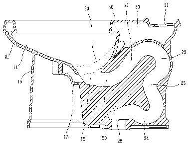
FICz 4 is a sectional view of a lateral side of a preferred embodiment of the
present mvenhon;
FIG. 5 is a bottom view of the preferred embodiment of the present invention;
and
FIG. 6 is a sketch diagram of the preferred embodiment of the present
2

CA 02527389 2005-11-21
invention, showing the water flow.
DETAILED DESCRIPTION OF THE INVENTION
As shown in FIGS. 4 and FIG. 5, a toilet of the preferred embodiment of the
S present invention comprises:
A bowl member 10 has a contraction portion 11, which is narrowed from a
top to a bottom thereof, a receiving portion 12 below the contraction portion
11, and a
converging portion 13 in front of the receiving portion 12. The converging
portion 13
has an injecting portion 14 and an inlet portion 15 at opposite ends thereof
with a
narrow interior diameter and a wider converging region 16 is at a center
thereof.
Behind the receiving portion 12 is a discharging pipe 20 and is communicated
therewith. The discharging pipe 20 has a rising section 21, a falling section
22, a
twisted section 23, a gathering section 24, and an outlet 25 in sequence.
Water flow
goes up in the rising section 21 and goes down in the falling section 22. The
twisted
section 23 is curved toward the receiving portion 12 first and curved back.
Finally, the
water flow goes out via the gathering section 24 and the outlet 25. Water
forms a
turbulent flow in the twisted section 23 and produces the siphon effect in the
gathering
section 24 to suck the waste and water in the receiving portion 12 out.
The bowl 10 has a chamber 30 at an end thereof with an inlet 31 to be
communicated with a tank (not shown in FIG). Water comes from the tank flows
into
the chamber 30 via the inlet 31. The bowl 10 has an annular up tunnel 40 at a
top
thereof. The up tunnel 40 is communicated with the chamber 30 and has bores 41
to
flow the water in the chamber 30 to the contraction portion 11.
The bowl 10 has two down tunnels 50 at opposite sides of the contraction
portion 11. The down tunnels 50 have ends communicated with the chamber 30 to
flow
3

CA 02527389 2005-11-21
the water in the tank to the down tunnels 50 via the chamber 30. Each of the
down
tunnels 50 have the other end extended downwards to a position in front of the
receiving portion 12 to form a U-turn section 51. The down tunnels 50 make an
inward
U-turn, with an angle greater than 90 degree and less than 180 degree, and are
communicated with the inlet portion 15 of the converging portion 13. Water
flowing
through the down tunnels 50 will go to the converging portion 13 first and
converge
together to go to the discharging pipe 20.
In a normal condition, the receiving portion 12 and the converging portion
13 are under the water. When user flushes the toilet of the present invention,
water in
the tank flows to the chamber 30 via the inlet 31 first, and then a part of
the water
flows through the up tunnel 40 and the bores 41 and to the contraction portion
11 and
finally arrive the receiving portion 12 to wash the waste on the contraction
portion 11.
The other part of the water flows through the down tunnels 50 respectively and
converges in the converging portion 13 and flows to the injecting portion 14
to inject
toward the discharging pipe 20. The present invention provides two water flows
converging together before injecting out so that the present invention has no
the
conventional condition that water flow goes faster at the exterior side and
slower at the
interior side when it makes a turn. The present invention has two water flows
converging together naturally and with a mountain peaks-like distribution,
with the
mountain peaks pointing the discharging pipe 20 and spreading out, in the
receiving
portion 12. As a result, the present invention can flush the waste out
directly, normally,
and efficiently. In the discharging pipe 20, the siphon effect is working to
provide a
well flushing power.
In addition, the present invention further provides a narrowed injecting
portion 14 behind the converging flow. According to the fluid mechanics, the
quantity
4

CA 02527389 2005-11-21
of water flowing in is equal to the quantity of water flowing out, such that
water flows
through the narrowed injecting portion 14 will have a faster speed that will
increase the
flushing power.

Representative Drawing
A single figure which represents the drawing illustrating the invention.
Administrative Status

2024-08-01:As part of the Next Generation Patents (NGP) transition, the Canadian Patents Database (CPD) now contains a more detailed Event History, which replicates the Event Log of our new back-office solution.

Please note that "Inactive:" events refers to events no longer in use in our new back-office solution.

For a clearer understanding of the status of the application/patent presented on this page, the site Disclaimer , as well as the definitions for Patent , Event History , Maintenance Fee  and Payment History  should be consulted.

Event History

Description Date
Letter Sent 2024-05-21
Letter Sent 2023-11-21
Common Representative Appointed 2019-10-30
Maintenance Request Received 2016-11-09
Maintenance Request Received 2015-11-09
Maintenance Request Received 2014-11-05
Maintenance Request Received 2013-11-19
Maintenance Request Received 2012-11-02
Grant by Issuance 2010-06-29
Inactive: Cover page published 2010-06-28
Pre-grant 2010-04-13
Inactive: Final fee received 2010-04-13
Notice of Allowance is Issued 2010-03-01
Letter Sent 2010-03-01
Inactive: Approved for allowance (AFA) 2010-02-17
Amendment Received - Voluntary Amendment 2009-08-19
Inactive: S.30(2) Rules - Examiner requisition 2009-04-02
Application Published (Open to Public Inspection) 2007-03-29
Inactive: Cover page published 2007-03-28
Amendment Received - Voluntary Amendment 2006-10-18
Letter Sent 2006-09-22
Request for Examination Requirements Determined Compliant 2006-08-30
All Requirements for Examination Determined Compliant 2006-08-30
Request for Examination Received 2006-08-30
Inactive: First IPC assigned 2006-07-28
Inactive: IPC assigned 2006-07-28
Letter Sent 2006-01-06
Filing Requirements Determined Compliant 2006-01-06
Application Received - Regular National 2006-01-06
Inactive: Filing certificate - No RFE (English) 2006-01-06

Abandonment History

There is no abandonment history.

Maintenance Fee

The last payment was received on 2009-10-22

Note : If the full payment has not been received on or before the date indicated, a further fee may be required which may be one of the following

  • the reinstatement fee;
  • the late payment fee; or
  • additional fee to reverse deemed expiry.

Please refer to the CIPO Patent Fees web page to see all current fee amounts.

Owners on Record

Note: Records showing the ownership history in alphabetical order.

Current Owners on Record
GLOBE UNION INDUSTRIAL CORP.
Past Owners on Record
JIN-YI WANG
TSUNG-YI LO
Past Owners that do not appear in the "Owners on Record" listing will appear in other documentation within the application.
Documents

To view selected files, please enter reCAPTCHA code :


To view images, click a link in the Document Description column. To download the documents, select one or more checkboxes in the first column and then click the "Download Selected in PDF format (Zip Archive)" or the "Download Selected as Single PDF" button.

List of published and non-published patent-specific documents on the CPD .

If you have any difficulty accessing content, you can call the Client Service Centre at 1-866-997-1936 or send them an e-mail at CIPO Client Service Centre.


Document
Description 
Date
(yyyy-mm-dd) 
Number of pages   Size of Image (KB) 
Abstract 2005-11-21 1 21
Description 2005-11-21 5 161
Claims 2005-11-21 2 55
Drawings 2005-11-21 5 67
Representative drawing 2007-03-09 1 14
Cover Page 2007-03-20 1 44
Claims 2009-08-19 2 50
Cover Page 2010-06-03 2 49
Courtesy - Patent Term Deemed Expired 2024-07-02 1 532
Courtesy - Certificate of registration (related document(s)) 2006-01-06 1 104
Filing Certificate (English) 2006-01-06 1 157
Acknowledgement of Request for Examination 2006-09-22 1 176
Reminder of maintenance fee due 2007-07-24 1 112
Commissioner's Notice - Application Found Allowable 2010-03-01 1 165
Commissioner's Notice - Maintenance Fee for a Patent Not Paid 2024-01-02 1 541
Fees 2007-10-24 1 49
Fees 2008-10-31 1 52
Fees 2009-10-22 1 53
Correspondence 2010-04-13 1 52
Fees 2010-11-12 1 47
Fees 2011-11-08 1 49
Fees 2012-11-02 1 52
Fees 2013-11-19 1 43
Fees 2014-11-05 1 44
Maintenance fee payment 2015-11-09 1 42
Maintenance fee payment 2016-11-09 1 41
Maintenance fee payment 2020-11-11 1 24
Maintenance fee payment 2021-11-10 1 24
Maintenance fee payment 2022-11-07 1 24