Language selection

Search

Patent 2527455 Summary

Third-party information liability

Some of the information on this Web page has been provided by external sources. The Government of Canada is not responsible for the accuracy, reliability or currency of the information supplied by external sources. Users wishing to rely upon this information should consult directly with the source of the information. Content provided by external sources is not subject to official languages, privacy and accessibility requirements.

Claims and Abstract availability

Any discrepancies in the text and image of the Claims and Abstract are due to differing posting times. Text of the Claims and Abstract are posted:

  • At the time the application is open to public inspection;
  • At the time of issue of the patent (grant).
(12) Patent: (11) CA 2527455
(54) English Title: THREAD SUPPORTING STABILIZER ASSEMBLY
(54) French Title: ENSEMBLE STABILISATEUR DE SOUTIEN DE FILETAGE
Status: Granted and Issued
Bibliographic Data
(51) International Patent Classification (IPC):
  • F16L 55/07 (2006.01)
  • F16L 57/00 (2006.01)
(72) Inventors :
  • HUTTON, PETER B. (United States of America)
(73) Owners :
  • PETER B. HUTTON
(71) Applicants :
  • PETER B. HUTTON (United States of America)
(74) Agent: GOWLING WLG (CANADA) LLP
(74) Associate agent:
(45) Issued: 2013-01-15
(22) Filed Date: 2005-11-17
(41) Open to Public Inspection: 2006-05-17
Examination requested: 2010-10-05
Availability of licence: N/A
Dedicated to the Public: N/A
(25) Language of filing: English

Patent Cooperation Treaty (PCT): No

(30) Application Priority Data:
Application No. Country/Territory Date
29/221,625 (United States of America) 2005-01-21
60/628,127 (United States of America) 2004-11-17

Abstracts

English Abstract

A pressure tap assembly for connection between a pipeline flange and a manifold and/or transmitter in which assembly means are provided for transmitting the load from a threaded end of the tap to the body of the tap. In one embodiment the tap is provided with a tap body having an integral stabilizing flange. By the use of a force providing device the stabilizing flange is forced in a direction away from the pipeline flange thereby reducing the load on the threads on the threaded end of the tap. A combination of a stabilizing nut and stabilizer base can be used to provide the force.


French Abstract

Un dispositif de prise sous pression pour une connexion entre une bride de tuyau et une tubulure et/ou un transmetteur dans lequel les moyens du dispositif sont fournis pour transmettre la charge d'une extrémité filetée de la prise sous pression vers le corps de la prise. Dans une réalisation, la prise fournie est dotée d'un corps de prise comprenant une bride stabilisatrice intégrée. L'utilisation d'un dispositif fournissant la force à la bride stabilisatrice est forcée dans une direction éloignée de la bride du tuyau, réduisant ainsi la charge sur le filetage de l'extrémité filetée de la prise. Une combinaison d'un écrou stabilisateur et d'une base stabilisatrice peut être utilisée pour fournir la force.

Claims

Note: Claims are shown in the official language in which they were submitted.

-5-
I. CLAIM:
1. A method of stabilizing a pressure tap assembly wherein a pressure tap
is threadedly engaged with a source of pressurized fluid, the pressure tap
assembly
comprising:
(a) a pressure tap body having distal and proximal ends and a stabilizing
flange intermediate said distal and proximal ends;
(b) said distal end comprising a futbol flange;
(c) said proximal end comprising an NPT thread;
(d) a stabilizer base adjacent said proximl end for contact with a vessel
containing a source of pressurized fluid;
(e) a stabilizing nut for impinging on said stabilizing flange and said
stabilizer base;
the method comprising forcing the stabilizer base and stabilizing flange in
opposite directions.
2. The method of claim 1 where the forcing reduces the load on the NPT
threads.
3. The method of claim 1 where the forcing is created by threaded
engagement of the stabilizing nut and stabilizer base.
4. A pressure tap assembly comprising:
(a) a pressure tap body having distal and proximal ends and a stabilizing
flange intermediate said distal and proximal ends;

-6-
(b) said distal end comprising a futbol flange;
(c) said proximal end comprising an NPT thread;
(d) a stabilizer base adjacent said proximl end for contact with a vessel
containing a source of pressurized fluid;
(e) a stabilizing nut for impinging on said stabilizing flange and said
stabilizer base.
5. The pressure tap assembly of claim 4 when said stabilizer flange is
integral with the tap body.
6. The pressure tap assembly of claim 5 when said stabilizer flange is made
in one piece with the tap body.
7. The pressure tap assembly of claim 4 when said stabilizer base defines a
bore which is internally threaded.
8. The pressure tap assembly of claim 7, wherein said internally threaded
bore of said stabilizer base is threadedly engageable with said stabilizing
nut.
9. The pressure tap assembly of claim 4 which at least a portion of said
stabilizing nut is polygonal in shape.
10. The pressure tap assembly of claim 8 when said stabilizing nut has a
thread on an exterior section thereof.
11. The pressure tap assembly of claim 4 is threaded engagement with a
vessel containing a fluid under pressure.

-7-
12. The pressure tap assembly of claim 11 where the vessel is a pipeline.
13. The pressure tap assembly of claim 12 where the pipeline comprises a
flange into which the pressure tap is threadedly engaged.
14. The pressure tap assembly of claim 13 where the futbol flange is
connected to a manifold.
15. The pressure tap assembly of claim 13 where the futbol flange is
connected to a transmitter.
16. The pressure tap assembly of claim 14 where the manifold is connected
to a transmitter.

Description

Note: Descriptions are shown in the official language in which they were submitted.


CA 02527455 2005-11-17
THREAD SUPPORTING STABILIZER ASSEMBLY
BACKGROUND OF THE INVENTION
1. Field of Invention
The invention relates to pressure tap assemblies, and more specifically to a
tap
assembly which is stabilized such that tendency for leaking and/or failure by
shearing is
reduced.
2. Description of the related art
Pressure taps, such as used in a vessel, including a pipeline on one or both
sides
of an orifice plate, are useful to measure pressure in a conduit, such as a
pipeline
carrying liquid gaseous fluid, which pressure measurement can be used for
various
calculations, such as flow rate; metering, etc. The taps can be fluidly
connected to a
pressure sensor, which in some cases acts as a pressure transmitter. When used
on
either side of an orifice plate the high and low pressure measurements can be
used as
inputs to so-called "smart" differential pressure transmitters.
The taps themselves are standardized with NPT threads. By means of pipe
fittings or manifolds the taps can be placed in fluid communication with
pressure, or
differential pressure, transmitters for purposes of providing information on
the pressure
of the fluid inside the conduit.
One of the shortcomings of the conventional taps has been the propensity of
the
load on the taps being transmitted to the NPT threads causing leaking of the
fluid in the
pipeline to escape to the environment. In cases where the pipeline is carrying
combustible or explosive fluids, e.g. oil or natural gas, the escape of the
fluid from the
threads could also result in personal injury and damage to property. In
extreme
loadings, the NPT threads of the taps are stressed to their elastic limit
resulting in
shearing of the taps and release of the fluid in great quantities to the
environment.

CA 02527455 2005-11-17
-2-
Thus, it is an object of the present invention to provide stabilized taps of a
construction where the propensity of leaking of fluid through the NPT threads
is
reduced. It is also an object of the invention to provide a stabilized tap
construction
such that rocking of the taps are reduced, even when taps are subjected to
external static
and dynamic loads, such as weight of a transmitter and associated "plumbing",
e.g.
manifolds, which are in fluid communication with the taps of the invention.
It is a still further object of the invention to provide new tap construction
and
function which will diminish the tendency of a tap to fail by either leakage
past the
NPT threads, or shearing of the tap itself due to external forces placed upon
the tap.
These and other objects of the invention will become apparent by reference to
the following description of the preferred embodiments and the appended
drawings.
BRIEF DESCRIPTION OF THE DRAWINGS
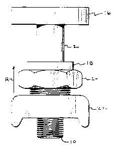
Figure 1 is a schematic representation of a front view of the thread
supporting stabilizer
assembly according to one embodiment of the invention;
Figure 2 is a side view of the thread supporting stabilizer assembly of Figure
1;
Figure 3 is a top view of the thread supporting stabilizer assembly of Figure
1;
Figure 4 is a bottom view of the thread supporting stabilizer of Figure 1;
Figure S is a cross-sectional view of the thread supporting stabilizer along
lines 5-5 of
Figure 2;
Figure 6 is an alternative embodiment of the top view of the thread supporting
stabilizer
assembly shown in Figure 3, with Figures 1-2, 4 and 5 being the same in this
alternative
embodiment; and
Figure 7 is a partial cross-sectional view along lines 7-7 of Figure 6.

CA 02527455 2005-11-17
-3-
DETAILED DESCRIPTION OF THE PREFERRED EMBODIMENTS
As shown in Figure 1 is a schematic representation of the pressure tap
assembly
according to the present invention in which, at a proximal end of tap 14, the
NPT
threadsl0 are threadedly engaged with a threaded bore 11 in a conduit, such as
pipeline
flange 12. At the distal end of the tap I4 is a so-called "futbol" flange 16
named
because it has the shape of an American football. These futbol flanges 16 are
standardized in the industry to mate with the other "plumbing" fittings to
place the
fluid in the interior of the pipeline flange 12 in fluid communication with
the gauges or
pressure transmitters (not shown) which are ultimately connected therewith.
Sometimes the futbol flanges 16 are connected to a manifold provided with one
or more
valves to direct the high and low pressure fluids to the appropriate inputs of
a
differential pressure transmitter. In the manifolds some valves may act as
equalizer
valves or drain valves. Other times the futbol flanges 16 may be attached
directly to a
flange of a pressure gauge or transmitter (not shown).
The taps of the invention are also provided with a stabilizing flange 18 which
is
mounted intermediate the futbol flange 16 and the NPT threads 10. As shown in
Figure
stabilizing flange 18 is integral with body 20 of tap 14. In some instances,
the
stabilizing flange is made in one piece with body of tap 14. In other
embodiments it
may be made of a separate piece which is made integral to body 20 by
techniques such
as welding, pins, or other fastening techniques. Thus it can be readily seen
that when a
force is exerted upon stabilizing flange 18, which force is directed in the
direction of
the arrow A, the NPT threads 10 are brought into tight engagement with the
threads in
the threaded bore of pipeline flange I2.
In order to create the force acting upon the stabilizing flange 18, use is
made of
the interaction between a stabilizer base 22 and stabilizing nut 24. The
stabilizer base
defines an internal threaded bore 26 which is threadedly engaged by the
external
threads 28 of stabilizing nut 24 as best illustrated in Figure 5. As one
relatively
manipulates the stabilizer base 22 and stabilizing nut 24 to force them away
from each
other, a force will be created between pipeline flange 12 and stabilizing
flange 18. In
addition, by making the stabilizer base relatively larger than the NPT threads
10, the

CA 02527455 2005-11-17
-4-
tendency of the tap 14 to "rock" in its threaded engagement with threaded bore
11 will
be reduced. Although illustrated for use with pipeline flanges of 6, 8 and 12
inches, the
invention is not so limited and can be used with pipeline flanges of any size.
Moreover,
the drawings are merely schematic and not intended to limit the size of the
stabilizer
base 22, the stabilizing nut 24, the stabilizing flange 18 or the dimensions
of the futbol
flange 16.
The invention is also not limited to the specific embodiments illustrated and
described as those of ordinary skill in the art upon reading this disclosure
will readily
envision modifications to the preferred embodiments without departing from the
spirit
and scope of the disclosed invention. For example, the shape of the stabilizer
base may
be modified, or provided with individually adjustable feet. The futbol flanges
may be
changed in shape so as to mate with existing or specially designed manifolds,
transmitters, gauges or other "plumbing" components. The manner of shaping the
futbol flange to receive bolts or studs can be as having individual apertures
30, 31
(Figs.6-7) or elongated slots 32, 33 (Fig.3). The stabilizing flange may be
integral as
shown and described or itself may compromise an adjustment feature, i.e. it
may have
internal threads cooperating with a threaded portion of the body of the tap
such that its
relative position on the body may be changed. The stabilizing nut may not be
hex
shaped but may be made with only two flats, square, octagon or other polygonal
shape
or even partially arcuate. It is to be understood that the invention is not
limited to the
described embodiments which are given by way of illustration only as it will
be readily
understood by these skilled in the art that various embodiments and
modifications of
the invention may be made without departing in spirit or scope from the
appended
claims.

Representative Drawing
A single figure which represents the drawing illustrating the invention.
Administrative Status

2024-08-01:As part of the Next Generation Patents (NGP) transition, the Canadian Patents Database (CPD) now contains a more detailed Event History, which replicates the Event Log of our new back-office solution.

Please note that "Inactive:" events refers to events no longer in use in our new back-office solution.

For a clearer understanding of the status of the application/patent presented on this page, the site Disclaimer , as well as the definitions for Patent , Event History , Maintenance Fee  and Payment History  should be consulted.

Event History

Description Date
Change of Address or Method of Correspondence Request Received 2021-03-19
Revocation of Agent Request 2021-03-19
Appointment of Agent Request 2021-03-19
Common Representative Appointed 2019-10-30
Change of Address or Method of Correspondence Request Received 2018-01-16
Grant by Issuance 2013-01-15
Inactive: Cover page published 2013-01-14
Pre-grant 2012-09-12
Inactive: Final fee received 2012-09-12
Notice of Allowance is Issued 2012-03-13
Letter Sent 2012-03-13
Notice of Allowance is Issued 2012-03-13
Inactive: Approved for allowance (AFA) 2012-03-02
Letter Sent 2010-10-14
Request for Examination Received 2010-10-05
Request for Examination Requirements Determined Compliant 2010-10-05
All Requirements for Examination Determined Compliant 2010-10-05
Small Entity Declaration Determined Compliant 2007-11-19
Small Entity Declaration Request Received 2007-11-19
Application Published (Open to Public Inspection) 2006-05-17
Inactive: Cover page published 2006-05-16
Inactive: IPC assigned 2006-05-09
Inactive: First IPC assigned 2006-05-09
Inactive: IPC assigned 2006-05-09
Inactive: Filing certificate - No RFE (English) 2006-01-20
Filing Requirements Determined Compliant 2006-01-11
Inactive: Filing certificate - No RFE (English) 2006-01-11
Application Received - Regular National 2006-01-09
Small Entity Declaration Determined Compliant 2005-11-17

Abandonment History

There is no abandonment history.

Maintenance Fee

The last payment was received on 2012-11-09

Note : If the full payment has not been received on or before the date indicated, a further fee may be required which may be one of the following

  • the reinstatement fee;
  • the late payment fee; or
  • additional fee to reverse deemed expiry.

Please refer to the CIPO Patent Fees web page to see all current fee amounts.

Fee History

Fee Type Anniversary Year Due Date Paid Date
Application fee - small 2005-11-17
MF (application, 2nd anniv.) - small 02 2007-11-19 2007-11-19
MF (application, 3rd anniv.) - small 03 2008-11-17 2008-11-06
MF (application, 4th anniv.) - small 04 2009-11-17 2009-10-15
Request for examination - small 2010-10-05
MF (application, 5th anniv.) - small 05 2010-11-17 2010-11-03
MF (application, 6th anniv.) - small 06 2011-11-17 2011-10-31
Final fee - small 2012-09-12
MF (application, 7th anniv.) - small 07 2012-11-19 2012-11-09
MF (patent, 8th anniv.) - small 2013-11-18 2013-08-21
MF (patent, 9th anniv.) - standard 2014-11-17 2014-11-10
MF (patent, 10th anniv.) - standard 2015-11-17 2015-11-16
MF (patent, 11th anniv.) - standard 2016-11-17 2016-11-14
MF (patent, 12th anniv.) - standard 2017-11-17 2017-11-13
MF (patent, 13th anniv.) - standard 2018-11-19 2018-11-12
MF (patent, 14th anniv.) - small 2019-11-18 2019-11-08
MF (patent, 15th anniv.) - small 2020-11-17 2020-11-13
MF (patent, 16th anniv.) - small 2021-11-17 2021-11-12
MF (patent, 17th anniv.) - small 2022-11-17 2022-11-11
MF (patent, 18th anniv.) - small 2023-11-17 2023-11-10
Owners on Record

Note: Records showing the ownership history in alphabetical order.

Current Owners on Record
PETER B. HUTTON
Past Owners on Record
None
Past Owners that do not appear in the "Owners on Record" listing will appear in other documentation within the application.
Documents

To view selected files, please enter reCAPTCHA code :


To view images, click a link in the Document Description column. To download the documents, select one or more checkboxes in the first column and then click the "Download Selected in PDF format (Zip Archive)" or the "Download Selected as Single PDF" button.

List of published and non-published patent-specific documents on the CPD .

If you have any difficulty accessing content, you can call the Client Service Centre at 1-866-997-1936 or send them an e-mail at CIPO Client Service Centre.


Document
Description 
Date
(yyyy-mm-dd) 
Number of pages   Size of Image (KB) 
Cover Page 2012-12-31 2 39
Abstract 2005-11-17 1 15
Description 2005-11-17 4 176
Claims 2005-11-17 3 61
Drawings 2005-11-17 2 56
Representative drawing 2006-04-20 1 8
Cover Page 2006-05-10 1 35
Representative drawing 2012-12-31 1 7
Filing Certificate (English) 2006-01-20 1 157
Filing Certificate (English) 2006-01-11 1 157
Reminder of maintenance fee due 2007-07-18 1 112
Reminder - Request for Examination 2010-07-20 1 120
Acknowledgement of Request for Examination 2010-10-14 1 177
Commissioner's Notice - Application Found Allowable 2012-03-13 1 162
Correspondence 2007-11-19 2 69
Fees 2009-10-15 1 40
Correspondence 2012-09-12 2 48