Note: Descriptions are shown in the official language in which they were submitted.
CA 02528328 2005-12-06
WO 2004/110081 PCT/IB2003/002523
METHOD AND APPARATUS FOR SWITCHING MOBILE STATION
BETWEEN AUTONOMOUS AND SCHEDULED TRANSMISSIONS
TECHNICAL FIELD:
This invention relates generally to mobile wireless communication systems and,
more
specifically, relates to methods and apparatus for operating a mobile station,
such as a
cellular telephone, with a base station when sending data on a reverse channel
from the
mobile station to the base station in a cdma2000-type system.
BACKGROUND:
In a data communications system where a transmission resource is shared by
multiple
users, or where the transmission quality of a user can be affected by another
user, there
1 S are generally two modes of channel operation. These may be referred to
generally as an
autonomous mode and as a scheduled mode. The autonomous mode does not
necessarily
require a resource request-grant relationship between the transmitters and the
receiver
prior to a communication, while the scheduled mode requires the presence of an
arbiter of
some type (e.g., at the receiver) to authorize and/or schedule transmissions
for the
multiple transmitters.
Each mode of operation has its advantages and its disadvantages. For example,
the
autonomous mode is well suited for small packet or circuit-like transmissions,
while the
scheduled mode is well suited for latency-insensitive transmissions.
For the cdma2000 lxEV-DV (or cdma2000, Revision D) reverse link framework, it
is
desirable to support both the autonomous mode and the scheduled mode of
operation for
the Reverse Supplemental Channel (R-SCH). However, many technical issues need
to be
resolved to make the autonomous and scheduled modes mutually compatible. For
example, in order to operate these two modes alternatively, one important
issue concerns
how to best transition between the two modes.
1
CA 02528328 2005-12-06
WO 2004/110081 PCT/IB2003/002523
Efforts have begun to standardize a complementary uplink structure, Enhanced
Uplink
Packet Access (EUPA) in 3GPP, to IxEV-DV Revision D in 3GPP2. However, at
present
there is no provision for transitioning a mobile station between the
autonomous and the
scheduled transmission modes.
As a result, as presently specified the base station may not know, at any
given time, when
the mobile station needs to transmit data in the packet data system.
SUMMARY OF THE PREFERRED EMBODIMENTS
The foregoing and other problems are overcome, and other advantages are
realized, in
accordance with the presently preferred embodiments of these teachings.
It is an aspect of this invention to define a procedure to accomplish a
scheduled switching
mode for transitioning a mobile station between the autonomous transmission
mode and
the scheduled transmission mode.
Disclosed is a method for operating a mobile station with a base station, as
well as
apparatus for performing the method. The method includes, when the mobile
station is in
an Autonomous mode of operation, autonomously transmitting data from the
mobile
station to the base station on a reverse supplemental channel or a reverse
access channel
(e.g. R-EACH) from the mobile station to the base station; in response to
receiving an
acknowledgment indication from the base station, that comprises a reverse
channel
assignment message for the mobile station, switching the mobile station to a
Scheduled
mode of operation and transmitting the data from the mobile station on an
assigned
reverse channel.
In the preferred embodiment, when initiating the data transmission of
scheduled mode,
the mobile station transmits a Supplemental Channel Request Message and the
reverse
access channel is a Reverse Enhanced Access Channel. The acknowledgment
indication
is sent as part of a Supplemental Channel Assignment Message and further
includes
power control bits and data rate grant bits, where the power control bits and
data rate
2
CA 02528328 2005-12-06
WO 2004/110081 PCT/IB2003/002523
grant bits are received by the mobile station on a Common Power Control
Channel.
Transmitting the data from the mobile station on the assigned reverse channel
includes
also transmitting mobile station buffer activity bits and a data rate request
bit, and the
method further includes receiving, from the base station, a power control bit,
a data rate
S grant bit and an ACK/NACK indication. The data rate request bit is
preferably
transmitted as part of a dynamic buffer status report, and requests one of an
increase in
data rate, a decrease in data rate, or no change in the data rate, and the
data rate grant bit
is time multiplexed by the base station with the power control bit, and
indicates one of a
grant of the requested data rate or a denial of the requested data rate.
Also disclosed is a mobile station that includes an RF transceiver for
conducting
bidirectional wireless communications with a base station and a data processor
that
operates under the control of a stored program for, when the mobile station is
in an
Autonomous mode of operation, autonomously transmitting data from the mobile
station
to the base station on a reverse supplemental channel or a reverse access
channel from the
mobile station to the base station. The data processor is responsive to a
reception of an
acknowledgment indication from the base station that comprises a reverse
channel
assignment message for the mobile station, for switching the mobile station to
a
Scheduled mode of operation and for transmitting the data from the mobile
station on an
assigned reverse channel.
BRIEF DESCRIPTION OF THE DRAWINGS
The foregoing and other aspects of these teachings are made more evident in
the
following Detailed Description of the Preferred Embodiments, when read in
conjunction
with the attached Drawing Figures, wherein:
Fig. 1 is a simplified block diagram of a mobile communications system that is
suitable
for practicing the teachings of this invention;
Fig. 2 is a diagram for illustrating a state transition from an autonomous
transmission
mode to a scheduled transmission mode;
3
CA 02528328 2005-12-06
WO 2004/110081 PCT/IB2003/002523
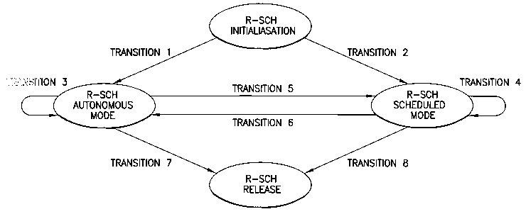
Fig. 3 is a state diagram that illustrates lxEV-DV R-SCH states and
transitions; and
Fig. 4 is a timing diagram that illustrates timing relationships between data
rate request
and grant, where the delays D 1 and D2 are configurable by the base station.
DETAILED DESCRIPTION OF THE PREFERRED EMBODIMENTS
By way of introduction, and referring to Fig. 1, there is shown as a
simplified block
diagram an embodiment of a wireless communications system 10 that is suitable
for
practicing this invention. The wireless communications system 10 includes at
least one
mobile station (MS) 100. Fig. 1 also shows an exemplary network operator 20
having,
for example, a node 30 for connecting to a telecommunications network, such as
a Public
Packet Data Network or PDN, at least one base station controller (BSC) 40 or
equivalent
apparatus, and a plurality of base transceiver stations (BTS) S0, also
referred to as base
stations (BSs), that transmit in a forward or downlink direction both physical
and logical
channels to the mobile station 100 in accordance with a predetermined air
interface
standard. A reverse or uplink communication path also exists from the mobile
station 100
to the network operator, which conveys mobile originated access requests and
traffic. A
cell 3 is associated with each BTS 50, where one cell will at any given time
be considered
to be a serving cell, while an adjacent cells) will be considered to be a
neighbor cell.
Smaller cells (e.g., picocells) may also be available.
The air interface standard can conform to any suitable standard or protocol,
and may
enable both voice and data traffic, such as data traffic enabling Internet 70
access and
web page downloads. In the presently preferred embodiment of this invention
the air
interface standard is compatible with a code division multiple access (CDMA)
air
interface standard, such as one known as cdma2000, although this is not a
limitation upon
the practice of this invention.
The mobile station 100 typically includes a control unit or control logic,
such as a
microcontrol unit (MCL~ 120 having an output coupled to an input of a display
140 and
4
CA 02528328 2005-12-06
WO 2004/110081 PCT/IB2003/002523
an input coupled to an output of a keyboard or keypad 160. The mobile station
100 may
be a handheld radiotelephone, such as a cellular telephone or a personal
communicator.
The mobile station 100 could also be contained within a card or module that is
connected
during use to another device. For example, the mobile station 10 could be
contained
within a PCMCIA or similar type of card or module that is installed during use
within a
portable data processor, such as a laptop or notebook computer, or even a
computer that
is wearable by the user.
The MCU 120 is assumed to include or be coupled to some type of a memory 130,
including a non-volatile memory for storing an operating program and other
information,
as well as a volatile memory for temporarily storing required data, scratchpad
memory,
received packet data, packet data to be transmitted, and the like. At least
some of this
temporary data can be stored in a data buffer 130A. The operating program is
assumed,
for the purposes of this invention, to enable the MCU 120 to execute the
software
1 S routines, layers and protocols required to implement the methods in
accordance with this
invention, as described in detail below, as well as to provide a suitable user
interface
(U~, via display 140 and keypad 160, with a user. Although not shown, a
microphone
and speaker are typically provided for enabling the user to conduct voice
calls in a
conventional manner.
The mobile station 100 also contains a wireless section that includes a
digital signal
processor (DSP) 180, or equivalent high speed processor or logic, as well as a
wireless
transceiver that includes a transmitter 200 and a receiver 220, both of which
are coupled
to an antenna 240 for communication with the network operator. At least one
local
oscillator, such as a frequency synthesizer (SYNTH) 260, is provided for
tuning the
transceiver. Data, such as digitized voice and packet data, is transmitted and
received
through the antenna 240.
The following discussion first describes a plurality of reverse supplemental
channel
(R-SCH) states and then describes state transitions. However, the teachings of
this
invention encompass all possible options for state design and state
transitions. This
invention also accommodates quality of service (QoS) needs for describing mode
J
CA 02528328 2005-12-06
WO 2004/110081 PCT/IB2003/002523
transitions.
As was stated earlier, an aspect of this invention is to enhance the reverse
link (uplink)
for IS2000 by the addition of a mode for the MS 100 to transition to
scheduling
transmissions when operating using autonomous transmissions. Fig. 2 depicts
the
scenario while the MS 100 is in the active state. The transition proceeds by
the following
Steps.
1. The MS 100 initiates data transfer on the R-EACH (Reverse Enhanced Access
Channel) or Reverse Supplemental Channel. A SCRM (supplemental channel request
message) can be transmitted over a reverse fundamental or reverse dedicated
channel to
request a scheduled mode operation, if the mobile station so desires.
2. If the BS 50 acknowledges the MS 100 transmission it sends an
acknowledgment
indicator (AI), if the reverse data is sent over the R-EACH in previous step.
The base
station also can send a SCAM (Supplemental Channel Assignment Message) for
informing the MS 100 of its channel assignment over a forward fundamental or
dedicated
channel. In addition, the BS 50 sends, via the CPCCH (Common Power Control
Channel), the PCB (power control bits), RGB (Rate Grant Bits), and the ACK/NAK
bits.
In response, the MS 100 transmits its data along with BAB (Buffer Activity
bits),
reflecting utilization of the data buffer 130A in Fig. 1, and RRB (Rate
Request bits).
If the BS 50 does not acknowledge the MS 100 transmission, i.e., the MS 100 is
denied
permission to transmit, the MS 100 repeats Step 1.
3. Assuming that the MS 100 has permission to transmit, the MS 100 and BS 50
jointly
"close the reverse data transmission loop" by the MS 100 sending its data,
plus the BAB
and RRB. The BS 50 responds with the PCB, the RGB and the appropriate one of
ACK/NAK.
When the MS 100 is in a Control Hold state the MS 100 first transitions out of
the
Control Hold state prior to initiating the data transfer.
6
CA 02528328 2005-12-06
WO 2004/110081 PCT/IB2003/002523
It can be appreciated that the use of this invention solves the previously
described
problem of the BS SO not having knowledge of when the MS 100 needs to transmit
data.
By the use of this invention the MS 100 is permitted to autonomously initiate
the data
transmission process, followed by BS 50 control of whether the data
transmission may
continue (entering into scheduled mode). The use of this invention can thus be
seen to
reduce the delay associated with reverse link transmission (startup).
Furthermore, since
the BS 50 has control ofwhether to permit the MS 100 to continue data
transmission, the
BS 50 can control the ROT (Rise Over Thermal).
A more detailed description of this invention is now provided.
As is shown in Fig. 3, there are four R-SCH states/modes and eight transitions
among
these states/modes in cdma2000 IxEV-DV. Note that the terminologies of "state"
and
"mode" are interchangeable in the ensuing discussion. The four states are the
R-SCH
initialization state, the R-SCH autonomous state, the R-SCH scheduled state,
and R-SCH
release state. These are now described in further detail.
A. R-SCH Initialization State
There are various possible (optional) ways to initialize the R-SCH in cdma2000
lxEV-DV.
Option 1:
The MS 100 sends a Supplemental Channel Request Message (SCRM) over the
R-DCCH/R-FCH to the BS. The BS SO acknowledges with Extended Supplemental
Channel Assignment Message (ESCAM) over F-FCH/F-DCCH/F-PDCH. This is same as
a conventional cdma2000 IxRTT approach.
Option 2:
The MS 100 sends a Supplemental Channel Request Mini Message (SCRMM) over the
R-DCCH/R-FCH to the BS S0. The BS 50 acknowledges with a Supplemental Channel
7
CA 02528328 2005-12-06
WO 2004/110081 PCT/IB2003/002523
Assignment Mini Message (SCAMM) over the F-FCH/F-DCCH/F-PDCH/F-CACH. This
is also the same as the conventional IxRTT approach.
Option 3:
The MS 100 sends a modified Supplemental Channel Request Message (SCRM) over
the
R-DCCH/R-FCH to the BS 50. The BS SO acknowledges with a modified Extended
Supplemental Channel Assignment Message (ESCAM) over the
F-FCH/F-DCCHlF-PDCH/. The modified SCRM includes additional parameters such as
the MS 100 buffer status, transmit power, QoS level and the MS 100 preferred
mode of
R-SCH operation (either Autonomous or Scheduled mode). The modified ESCAM
transmitted by the BS SO includes additional parameters such as the MAC ID
(medium
access control ID) to identify the MS 100 for R-SCH access, and the bit
positions of
control information (e.g. PC, RG, and A/N) in a power control subchannel
(i.e., the
F-FCH, F-DCCH, or F-CPCCH).
It should be noted that the MAC ID can be the same as the MAC ID for the F-
PDCH, if
the F-PDCH exists for the MS 100. Also, the MAC ID in SCAM can be replaced
with a
mapping identifier serving as a reverse link R-SCH access 117.
Option 4:
The MS 100 sends the Supplemental Channel Request Message (SCRM) over the
R-DCCH/R-FCH to the BS 50 (as in Option 1 above). The BS 50 acknowledges with
a
modified Extended Supplemental Channel Assignment Mini Message (ESCAMM) over
the F-FCH/F-DCCH/F-PDCH/F-CACH. The ESCAMM includes parameters as in the
modified ESCAM of Option 3.
Option 5:
The MS 100 sends a request over the R-EACH with additional parameters. The
additional
parameters specify the R-SCH characteristic and its preferred mode of
operation.
R-SCH Autonomous Mode
g
CA 02528328 2005-12-06
WO 2004/110081 PCT/IB2003/002523
In this mode of operation, the MS 100 can access the R-SCH without prior
authorization.
The operation in this mode has two options.
Option 1:
For fixed/constant data rate applications, all active MSs 100 can send data
over the
R-SCH autonomously using a data rate established by any of the following
rules:
(1) at a lowest data rate, i.e. 9.6kbps,
(2) at a low fixed data rate that is configurable by the BS 50, or
(3) at a minimum rate that is dynamically agreed upon by the MS 100 and the BS
S0. For
example, the data rate may be negotiated between the MS 100 and BS 50 by
exchanging
QoS BLOB according to IS-2000.5 procedures.
It is noted that all active MSs 100 should have been assigned with a MAC ID in
the
R-SCH initialization state or in the F-PDCH assignment phase. The MAC ID is
used by
the BS 50 to distinguish between multiple autonomous mode MSs 100. However,
the BS
50 also can distinguish multiple autonomous mode MSs 100 by decoding the MS
100
long code, without having knowledge of the MAC ID.
This option can be used to advantage for short frame transmission or low data
rate
applications.
Option 2:
Similar to the cdma20001 xEV-DO (also referred to as HDR), the MS 100, along
with the
R-SCH user traffic transmission, can explicitly send Rate Indication
information over a
reverse channel to indicate the data rate that is being used in the present R-
SCH frame.
The reverse Rate Indication channel may be a separate dedicated Walsh-coded
channel, a
common channel, or a channel that is time-multiplexed with other channels.
R-SCH Scheduled Mode
There are two options available for the R-SCH scheduled mode.
9
CA 02528328 2005-12-06
WO 2004/110081 PCT/IB2003/002523
Option 1:
Similar to cdma2000 IxRTT, the R-SCH procedures and relevant messages are
used. The
MS 100 requests R-SCH channel assignment, and the BS 50 schedules and assigns
a
R-SCH channel with a specific data rate and time duration.
Option 2:
For variable data rate applications, the following mode of operation can also
be
considered as a "semi-scheduled" mode.
MS 100 Procedures:
The MS 100 begins with the autonomous mode at a low data rate, as defined
above.
While sending data over the R-SCH, the MS 100 also sends a "Data Rate Request"
to the
BS 50. The Data Rate Request has the following characteristics. The Data Rate
Request
is 1-bit of information with three-state modulation (i.e., -1, 0, and 1), and
it may be
carned over an uplink overhead dedicated or common channel, or it may be
carried over
the R-SCH with a special Multiplexing option, where the MS 100 traffic and
control
information are multiplexed. The Data Rate Request may also be reflected in
the MS 100
dynamic buffer status, QoS level and transmit power report to the BS 50. In
other words,
the Data Rate Request bit can be referred to as the BAB (buffer activity bit).
The
definition of the Data Rate Request is as follows:
If BAB = INCREASE = l, the MS 100 is requesting to transmit on the R-SCH at
the data
rate of (current data rate + incremental rate), where the incremental rate =
increased step
rate,
If BAB = DECREASE = -1, the MS 100 is requesting to transmits on the R-SCH at
the
data rate of (current data rate - decremented rate),
If BAB = CONSTANT = 0, the MS 100 is requesting to transmit on the R-SCH at
the
same data rate as the current data rate.
BS SO Procedures:
Upon receiving the Data Rate Request of one of INCREASE/DECREASE/CONSTANT
from the MS 100, the BS 50 acknowledges (i.e., it either grants or denies) the
MS 100
CA 02528328 2005-12-06
WO 2004/110081 PCT/IB2003/002523
with a 1-bit information (feedback) of GRANT/DENY. This 1-bit information has
the
following characteristics. It is carried over the power control sub-channels
within the
F-FCH, F-DCCH, or F-CPCCH, and is time-multiplexed with the power control bit
(in
F-FCH, F-DCCH, or F-CPCCH) and other control information. For higher
transmission
reliability of this bit, bit repetition may be used by the BS 50. A definition
of the
GRANT/DENY bit is as follows.
If the 1-bit feedback = GRANT = l, the BS 50 allows the MS 100 BAB request.
If the 1-bit feedback = DENY = -1, the BS 50 denies the MS 100 BAB request.
The autonomous data rate request (by the MS 100) and the grant (by the BS 50)
have a
certain timing relationship. Fig. 4 illustrates one non-limiting example of
the timing
relationship. Special notes for the timing relationship shown in Fig. 4 are as
follows.
For Step 1-a (top trace) and 1-b (second to top trace), at any Power Control
Group (PCG),
where there are 16 PCGs in one 20 ms frame) any MS 100 (e.g. MS 100 #1 or MS
100
#2) can request to increase, decrease, or maintain the data rate. After Delay
time Dl, the
BS 50 receives and processes the request. The BS 50 sends the acknowledgment
to MS
100 at the designated PCG. After Delay time D2, the MS 100 starts transmitting
on the
R-SCH at the data rate that is agreed upon with the BS 50. The rate control
can be "per
PCG" or "per frame", and the value of D 1 and D2 is controlled or configured
by the BS
50.
R-SCH Release State
This state can be similar to that of cdma2000 lxRTT.
R-SCH State/Mode Transitions
The events (or methods) for the eight transitions shown in the state diagram
of Fig. 2 are
described as follows.
Transition l: The preferred mode of operation is embedded in the (modified) R-
SCH
assignment (mini) message.
1I
CA 02528328 2005-12-06
WO 2004/110081 PCT/IB2003/002523
Transition 2: The preferred mode of operation is embedded in the (modified) R-
SCH
assignment (mini) message.
Transition 3: For Option 1, the MS 100 remains in the Autonomous mode when it
is
continuing transmission at the low (or lowest) data rate. For Option 2, the MS
100
S remains in the Autonomous mode when the reverse rate indication indicates a
legitimate
data rate (instead of a mode switch indication).
Transition 4: The MS 100 remains in the Scheduled Mode so long as there is no
new
mode switch request in the SCRM, or the MS 100BS 50 still operate based on the
data
rate request-grant "scheduled" procedures defined herein.
Transition 5: For Option 1, the preferred mode of operation is embedded in the
(modified) R-SCH assignment (mini) message. For Option 2, the transition
trigger may
be implemented with the QoS level, with higher QoS needs corresponding to the
Scheduled Mode and its transition.
Transition 6: For Option 1, the R-SCH-assigned duration timer is used as the
trigger, i.e.,
1 S after the duration of the scheduled transmission, the MS 100 reverts back
to the
Autonomous Mode. For Option 2, the preferred mode of operation is embedded in
the
(modified) R-SCH assignment (mini) message. For Option 3, the transition
trigger may
be implemented with the QoS level model, with lower QoS needs corresponding to
the
Autonomous Mode and its transition.
Transition 7: This can be similar to lxRTT, using R-SCH release messages and
procedures.
Transition 8: This can also be similar to lxRTT, using R-SCH release messages
and
procedures.
As has been described, for the cdma2000 IxEV-DV reverse link framework it is
desirable
to support both the Autonomous and the Scheduled Modes of operation for the R-
SCH.
The foregoing discussion of the invention has described each R-SCH state and
state
transition in detail, and furthermore applies equally to other possible state
designs and
state transitions. The QoS parameters can be used to support the presently
preferred state
transitions.
The foregoing description has provided by way of exemplary and non-limiting
examples
I2
CA 02528328 2005-12-06
WO 2004/110081 PCT/IB2003/002523
a full and informative description of the best method and apparatus presently
contemplated by the inventors for carrying out the invention. However, various
modifications and adaptations may become apparent to those skilled in the
relevant arts in
view of the foregoing description, when read in conjunction with the
accompanying
drawings and the appended claims. However, all such modifications of the
teachings of
this invention will still fall within the scope of this invention. Further,
while the method
and apparatus described herein are provided with a certain degree of
specificity, the
present invention could be implemented with either greater or lesser
specificity,
depending on the needs of the user. Further, some of the features of the
present invention
could be used to advantage without the corresponding use of other features. As
such, the
foregoing description should be considered as merely illustrative of the
principles of the
present invention, and not in limitation thereof, as this invention is defined
by the claims
which follow.
13