Note: Descriptions are shown in the official language in which they were submitted.
CA 02528400 2005-11-29
51331-324
REMOVABLE MODULE FOR A CONSOLE
BACKGROUND OF THE INVENTION
FIELD OF THE INVENTION
The present invention relates to the field of
consoles; more particularly to the field of mounting
accessories to a console.
DESCRIPTION OF RELATED ART
Consoles for playing video games and reproducing
media such as movies have increasing become a part of home
entertainment. Initial consoles, while enjoyable, were
somewhat limited in processing power and graphical
capabilities. Over time, however, consoles have significantly
increased in power and capabilities and now provide significant
levels of immersive entertainment. Thus, like home computers,
I5 individuals have come to expect to purchase a console for use
in home entertainment.
Home entertainment, it should be noted, encompasses
more than playing video games. Home entertainment includes the
ability to play movies and music and to provide other
capabilities as dictated by software. Thus, a console can
provide significant home entertainment value.
Consoles, while sharing certain similarities with
home computers, are unique because of the environment in which
they work. Modern consoles have powerful processors and
sophisticated video and sound reproduction capabilities.
Consoles can be used to reproduce movies and music in addition
to playing games that are highly immersive. Consoles, however,
like other powerful computers, generate significant amounts of
heat that typically must be removed by the use of heat transfer
- 1 -
CA 02528400 2005-11-29
51331-324
system such as one or more fans that creates an air flow
suitable for transfer of the heat via convection. Therefore,
sound generation is a significant issue for consoles because
background noise generated by fans is undesirable. Thus, while
a processor in a console still generates heat, the heat must be
handled in a more elegant fashion than is typical for most home
computers.
Part of the reason for the need for a more elegant
design is that consoles tend to be packaged in smaller housing
than most home computers. Thus, unlike a typically computer
packaged in a tower case, the console, while containing many
similar components, is packaged in a relatively compact space.
Often there is little or no extra space within the console.
Accordingly, upgrades to a console are more challenging than
upgrades to a home computer.
BRIEF SUMMARY OF THE INVENTION
A console is configured to include an outer housing
that provides a relatively slim and attractive profile. The
outer housing has a number of sides, including a front side, a
left side and a right side. A panel on a side of the console
is removable and covers a recessed surface and a cable
receptor. A hard disk drive ("HDD") is provided in a HDD
module that is configured to removably mount in the recessed
surface so that a cable connector extending from the HDD module
mates with the cable receptor during installation. A portion
of the HDD module extends beyond the recessed surface so as to
modify the profile of the console when the HDD module is
installed. Thus, a user can purchase a console without a HDD
and later purchase a HDD upgrade that is readily installed by
the user and the HHD upgrade can provide visual clues that the
console has been upgraded.
- 2 -
CA 02528400 2005-11-29
51331-324
BRIEF DESCRIPTION OF THE DRAWINGS
The present invention is illustrated by way of
example and not limited in the accompanying figures in which
like reference numerals indicate similar elements and in which:
Figure 1 illustrates an isometric view of an
embodiment of a console.
Figure 2 illustrates a plan view of an embodiment of
recessed surface of a console.
Figure 3 illustrates an isometric view of a door
configured to install in the recessed surface depicted in
Figure 2.
Figure 4 illustrates an isometric top view of an
embodiment of a module configured to be installed in the
recessed surface depicted in Figure 2.
Figure 5 illustrates an isometric bottom view of an
embodiment of a module configured to be installed in the
recessed surface depicted in Figure 2.
Figure 6 illustrates an isometric view of an
embodiment of a module being installed in the recessed surface
depicted in Figure 2.
Figure 7 illustrates an isometric view of the module
and console depicted in Figure 6 with the module in an
installed state.
Figure 8 illustrates an exploded view of an
embodiment of a hard disk drive module.
Figure 9 illustrates a partial exploded close-up view
of some of the components depicted in Figure 8.
- 3 -
CA 02528400 2005-11-29
51331-324
Figure 10 illustrates an isometric view of several of
the components depicted in Figure 9 with the components
assembled.
Figure 11 illustrates an isometric view of an
embodiment of a cable assembly.
DETAILED DESCRIPTION OF THE INVENTION
A console can be configured to be sold with our
without a module such as a hard disk drive ("HDD") module. If
sold without the HDD module, a cover panel is provided to cover
a recessed surface on an end of the console. When the
individual desires, the cover panel can be removed and the
module can be installed.
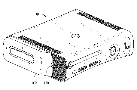
Turning to Figure l, an isometric view of a console
10 is provided. As depicted, console 10 includes a body 11 and
a first end 12. The first end 12 includes four support
extensions 13 configured to support the console 10 when the
console 10 is stood on its side. Another end of the console 10
can be similarly configured with support extensions. However,
to provide flexible orientation it is only beneficial to
include support extensions on one end in addition to including
support extensions on a bottom. Of course, extensions are not
required but eliminating extension makes it more difficult for
air to pass through the surface supporting the console 10.
Given the relatively slim profile of the console 10,
it is likely that console 10 can readily fit adjacent a
display, such as a TV or a monitor. The ability to stand the
console 10 on its side also provides additional flexibility for
positioning the console 10 in a desirable and attractive
manner.
- 4 -
CA 02528400 2005-11-29
51331-324
Turning to Figure 2, a view of an embodiment of a
second end 15 of console 10 is provided with an opening shown,
thus the cover panel 82 is not installed. Accordingly, an
upgrade module could be installed in the opening or recessed
surface. As depicted, a surface 14 is provided and surface 14
ends where a recessed surface 41 starts. Recessed surface 41
is defined by a perimeter wall 42 and a recessed floor 43. A
label 49 can be mounted on recessed floor 43 and a plurality of
holes 44 can be provided in recessed floor 43, the holes 44
defining air passageways so that air can enter the interior
portion of the console 10 through the recessed floor 43.
Recessed surface 41 also includes a latch retainer
45, a lip 46 and two latch arm retainers 47. The latch
retainer 45 and the lip 46 are configured to hold a cover panel
82 (not shown) in place so that the cover panel 82 does not
become inadvertently removed during normal usage of the console
10. The recessed floor 43 further includes a receptor hole 48
that is configured to provide a passageway through recessed
floor 43 so as to allow access to the cable receptor 69.
As noted above, the second end of console 10 includes
a surface 14 that is not recessed like the recessed floor 42.
Thus, the console 10 is configured so that when the cover panel
82 is installed, the outer surface of cover panel 82 is
substantially flush with surface 14 so that the second end 15
looks like a relatively continuous surface. The intersecting
line along which the cover panel 82 and the surface 14 join may
be visible.
Turning next to Figure 3, a rear isometric view of
the cover panel 82 is depicted. As noted above, cover panel 82
is configured to mate with the recessed surface 41 of the
console 10. In an alternative arrangement, not shown, the
- 5 -
CA 02528400 2005-11-29
51331-324
location of recessed surface 41 could be located on another
side of the console 10 provided other components of console 10
were appropriately arranged.
Cover panel 82 includes a button latch 83, a tongue
84, and a plurality of holes 85 that define air passageways
through the cover panel 82. To install cover panel 82 into
recessed surface 41, the tongue 84 is placed under the lip 46
and the button latch 83 of cover panel 82 is inserted into the
latch retainer 45. To uninstall the cover panel 82, the latch
84 is depressed in an inward direction and the cover panel 82
can be removed.
Turning to figure 4, an isometric view of a HDD
module 100 is provided. HDD module 100 includes a housing 101
that has a top surface 160. A vent 162 can be provided in top
surface 160 so as to allow air to enter housing 101. The shape
of the vent 162 is not important as long as air can be allowed
to enter through the display surface 112, thus the shape of
vent 162 could be more circular, could be square, or could be
any number of other shapes such as one or more lines. The HDD
module includes a latch 150 and latch arms 190, the function of
which will be discussed in greater detail below.
Figure 5 depicts the HDD module 100 of Figure 4 with
the bottom surface 170 visible. A tongue 176 is provided
opposite the latch 150 and the latch arms 190 and is configured
to cooperate with the latch arms 190 to hold the HDD module 100
in the installed or mounted position in a manner similar to
tongue 84. The bottom surface 170 includes a connector hole
171 through which a cable connector 122 extends from the
housing 101, the cable connector 122 being sealed to the
connector hole 171 by seal 180. A plurality of air holes 172
are also provided on the bottom surface 170, the plurality of
- 6 -
CA 02528400 2005-11-29
51331-324
air holes 172 configured to define passageways for allowing air
to pass through the bottom surface 170 and into the console 10
when the HDD module 100 is installed.
It should be noted that the air pressure of the
interior of the console 10 can be lowered by a fan system (not
shown) that directs air out of the console 10, thus air would
tend to enter the console 10 through other openings provided in
the console 10. Therefore, some of the passageways defined by
the holes 44 in recessed floor 43 are configured to correspond
to the passageways that are defined by holes 172 in the bottom
surface 170. In this manner, air can flow through the HDD
module 100 and help cool the HDD module 100 but, as the air
temperature of the air that passes through the HDD module 100
will typically be cooler than the heat sink mounted to the
processor inside the console 10, the air that enters the
console 10 through the HDD module 100 will still be useful in
transferring heat away from the heat sink.
Figure 6 depicts the installation process of the HDD
module 100. First the tongue 176, not visible, is inserted
under the lip 46. The HDD module 100 is then rotated around so
that the latch arms 190 engage latch arm retainers 47. As
depicted, the cable receptor 69 can be covered by a door 68
that pivots out of the way when the HDD module 100 is
installed. In an alternative embodiment, door 68 can be
replaced with a plug that can be removed prior to installing
the HDD module 100.
Figure 7 depicts the HDD module 100 in the installed
position. The latch 150 is visible and can be depressed and
when the latch 50 is depressed the HDD module 100 can be
removed. Thus, the HDD module 100 is removably mounted to the
console 10.
_ 7 _
CA 02528400 2005-11-29
51331-324
As depicted, the bottom surface 160 of HDD module 100
is in contact with the recessed floor 43. Thus, a portion of
the HDD module 100 is within the recessed surface 41 formed by
the wall 42 and the recessed floor 43. However, it is also
apparent that a portion of the HDD module 100 extends beyond
the wall 42. Thus, when installed, the HDD module 100 alters
the profile of the console 10. This allows individual to
quickly recognize that the console 10 has been upgraded. The
external shape of the HDD module 100 is not crucial and any one
of many alternative configurations may be used. It is
desirable, however, that a difference in the external shape of
console 10 be readily recognized once the HDD module 100 is
installed.
In such an embodiment, an individual could instantly
recognize that the console has been upgraded. It would also be
desirable to enhance the look of the console with the addition
of the upgrade. Such a configuration would make the upgrade
desirable from both a stylistic view point and a capabilities
view point, thus providing substantial value to a wider range
of individuals such that many individual will decide the value
of the upgrade is greater than the cost of the upgrade.
Turning now to Figure 8, an exploded view of an
embodiment of a HDD module 100 is depicted. The HDD module 100
includes HDD 202 that is supported by frame 210. HDD 202 can
be sized according to the requirements of the console and the
purpose of the HDD module 100. Thus, the HDD 202 could be
sized to provide 20, 40, 60, 80, 100 or more gigabytes of
storage. Naturally, other sizes are possible as HDD are now
available with 400 gigabytes of storage. Preferably the HDD is
configured to provide rapid access to the information stored on
the HDD 202, therefore a 7200 RPM based HDD may be preferable.
_ g _
CA 02528400 2005-11-29
51331-324
The frame 210, in addition to supporting the HDD 202,
also supports a cable assembly 120. A HDD cable connecter 121
connects the cable assembly 120 to the HDD 202 and the cable
connecter 122 extends through a passageway in the frame 210
that is defined by hole 212. Preferably the connector is
configured to allow rapid transfer of memory between the HDD
202 and is further configured to provide power to the HDD 202.
In an embodiment, the cable and the connectors are based on a
modified Serial ATA format.
To aid in supporting the HDD 202 and the cable
assembly 120 and the cable connector 122, a midframe 230 is
mounted to the frame 210 by a plurality of fasteners 235 so
that the HDD 202 and the cable assembly 220 are sandwiched
between the frame 210 and the midframe 230. Naturally, other
configurations of supporting the HDD 202 and the cable assembly
220 are possible.
A housing frame 140, a top surface 160 and a bottom
surface 170 are configured to support the HDD 202 and the cable
connector 122 by supporting the frame 210 and the midframe 230.
Top surface 160 can include one or more vents 162 that allow
air to pass through the housing top so as to provide cooling to
the HDD 202. While depicted as an edge in the shape of an
elongated hole, the vent 162 can be a variety of shapes and
configurations. Thus, the beneficial part about providing the
vent 162 is the ability to improve air flow through the HDD
module 100.
It is possible to eliminate the frame 210 or the mid
frame 230 and support the HDD 202 directly by the housing frame
140, the top surface 160, and the bottom surface 170 but some
of the vibration protection is lost when the frames are
eliminated. Further, the frame 210 and the midframe 230
- 9 -
CA 02528400 2005-11-29
51331-324
provide EMI grounding that typically is highly desirable when
packaging the HDD 202.
Top surface 160 and bottom surface 170 mount to
housing frame 140 and the combination of the housing frame 140,
the top surface 160 and the bottom surface 170 form a housing
101 for the HDD module 100. Thus, the outer surface of top
surface 160 is a display surface and the outer surface of
bottom surface 170 is a mounting surface. Bottom surface 170
includes a connector hole 171 that defines a passageway through
the bottom surface 170, the connector hole 171 configured to
correspond to the cable connector 122. To aid in sealing the
cable connector 122 to the bottom surface 170, a seal 180 is
located between the frame 210 and the bottom surface 170, the
seal 180 aligned with connector hole 171. As depicted, bottom
surface 170 also includes a plurality of air holes 172 that
define passageways in the housing bottom so that air can flow
through the bottom surface 170.
Pad 283 is also located between the frame 210 and the
bottom surface 170 and can provide vibration dampening. In an
embodiment, pad 283 is made of double sided sticky tape and
aids in the installation process.
To aid in holding the HDD module 100 in position, a
latch 150 is configured to cooperate with a biasing element 285
(e.g. a coil spring) and a latch arm 190. Label 298 can be
installed on bottom surface 170. Once the components are
properly positioned, a plurality of fasteners 299 are used to
hold the bottom surface 170, the housing frame 140, and the top
surface 160 together. The HDD module 100 is than ready to be
installed on the console.
Turning to Figures 9 and 10, an embodiment of the
components that allow the HDD module 100 to be installed is
- 10 -
CA 02528400 2005-11-29
51331-324
depicted. As previously discussed, a tongue 176 of the bottom
surface 170 is inserted in a corresponding lip 46 in the
recessed surface 41 of the console 10. Once so inserted, the
HDD module 100 can be rotated into position. To hold the HDD
module 100 in place, the latch arm 190 is mounted between the
top surface 160 and the bottom surface 170. Preferably at
least one support edge 163 is provided on top surface 160 to
help hold the latch arm 190 in position, however, as depicted a
plurality of support edges 163 are provided. The use of
multiple thin support edges 163 properly supports the latch arm
190 while helping to reduce friction so that the latch arm 190
can readily translate.
Latch arm 190 includes a latch ramp 191, latch
sliding surfaces 192 and latch biasing receptor 193. Referring
now to Figure 10, the latch arm 190 is shown installed on
bottom surface 170. The bottom surface 170 includes a biasing
support 177 and the biasing element 285 (shown as a coiled
spring) is positioned between the latch biasing receptor 193
and the biasing support 177. Thus, the biasing element 285
directs the latch arm 190 forward so that latch sliding
surfaces 192 extend from the housing 101.
Referring back to Figure 9, the latch 150 includes
arms 151 that engage channels 174 in the bottom surface 170.
The latch 150 further includes a translation surface 153
configure to interface with latch ramp 191. Thus, when the
arms 151 of latch 150 are installed in the channels 174, the
latch ramp 191 rests against the translation surface 153 of
latch 150. The force exerted on latch arm 190 by biasing
element 285 forces the latch to be in closed or first position.
When a force is exerted on the latch 150 that overcomes the
force provided by the biasing element 285, however, the latch
arm 190 is translated in a rearward direction.
- 11 -
CA 02528400 2005-11-29
51331-324
A force exerted on the latch sliding surfaces 192 can
also cause the latch arm 190 to translate in a rearward
direction. Given the angle of the latch sliding surface 192, a
force exerted orthogonal to the plane of translation will still
cause the latch arm 190 to translate. Thus, when the HDD
module 100 is inserted, pressing the latch sliding surfaces 192
against the latch arm retainers 47 will cause the latch arm 190
to translate until the HDD module 100 is fully inserted into
the recessed surface 41. Once inserted, however, the latch arm
190 will be directed forward by the force exerted on the latch
arm 190 by the biasing element 285 and the latch arm 190 will
extend under the latch arm retainers 47 to latch the HDD module
100 to the console 10.
As depicted, the top surface 160 can include a
connecting feature 165 the interfaces with mating connecting
feature 175 so that the two connecting features help to hold
the top surface 160 and the bottom surface 170 together.
As can be observed in Figure 10, the mounting side
194 of latch arm 190 is relatively flat. Thus, once mounted to
the console 10, the latch arm 190 will tend to hold the HDD
module 100 in position until the latch 150 is displaced. In
this manner, the HDD module can be readily installed on a
console 10 and just as readily be removed. Such a feature
allows for individuals to move a HDD module from one console to
another, thus information on a HDD module 100 can be translated
without the need to translate the entire console. Thus, an
individual could remove a HDD module containing high scores,
user profiles and saved games (as most games are driven by
either a CD or a DVD, the hard drive typically would not
include an actual game) and install the HDD module on a
friend's console so that both individuals could take advantage
of the saved data. In this manner, an individual could take
- 12 -
CA 02528400 2005-11-29
51331-324
travel with personalized data without the need to carry the
console itself.
Turning to Figure 11, an embodiment of the cable
assembly 120 is depicted. The cable connector 121 is
electrically connected to cable connector 122. As noted above,
the HDD module 100 is preferably not inserted in a straight
line but is rather rotated into position. Thus, the cable
connector 122 preferably should allow for insertion into the
cable receptor 69 without requiring perfect alignment. As
depicted, post 123 and post 124 have angled surfaces that aid
in allowing the cable connector 122 to be inserted into the
cable receptor 69. Thus, the cable connector 122 is configured
for angled insertion into the cable receptor 69 and cable
connector 122 can be rotatably mated to cable receptor 69.
Cable receptor 69 could be configured so to provide the
necessary clearance and tolerance. Alternatively, the cable
connector 122 and the cable receptor 69 could be configured so
as to require relatively straight insertion. In such a design,
preferably either two sets of latches would be provided or an
alignment guide would be provided along with at least one latch
so that aligning the cable connector 122 with the cable
receptor 69 would not be overly difficult.
Cable connector 122 includes a plurality of grounding
tabs 125 that flex and contact the frame 210 when the frame 210
and the cable assembly 120 are assembled together. In an
exemplary embodiment, the grounding tabs 125 help to provide
EMI grounding. To aid in ensuring the cable is properly
positioned, a ring 126 can be provided so that the space
between the frame 210 and the midframe 230 is occupied. This
aids in holding the cable connector 122 in place during
installation of the HDD module 100. To help protect the cable
- 13 -
CA 02528400 2005-11-29
51331-324
assembly 120, the seal 180 helps isolate the cable connector
120 from a side orientated shock event.
Thus, according to an embodiment, a HDD module 100
can be inserted into a recessed surface 41 of a console 10 with
a relatively simple rotational motion. The same HDD module 100
can also be removed in a relatively simple manner by depressing
a latch. Thus, an upgrade can be removably mounted to the
console.
One basic principle of economics is that an
individual will only pay for something that is perceived as
having at least as much value, and preferably more value, than
the cost. To provide the maximum value to the maximum number
of individual, a console can be offered with standard
capabilities. Additional features could then be offered as
upgrades for individuals who found the value of the features
exceeded the cost. According, a customizable console could
maximize the value enjoyed by the greatest number of people.
Naturally, the shape of the console or the upgrade can vary.
It is beneficial, however, to provide a visual difference
between the standard and an upgraded console.
The present invention has been described in terms of
preferred and exemplary embodiments thereof. Numerous other
embodiments, modifications and variations within the scope and
spirit of the appended claims will occur to persons of ordinary
skill in the art from a review of this disclosure.
- 14 -