Note: Descriptions are shown in the official language in which they were submitted.
T0463 SPE3W_TAN CA 02528689 2005-12-07
FUEL CELL STACK
BACKGROUND
The present invention relates to an anticorrosive structure of a fuel cell
stack,
and more particularly to an improvement technology providing for the increase
in
corrosion resistance and the reduction of cost of metal separators or terminal
plates.
Solid polymer fuel cell stacks have a stack structure constituted by stacking
the prescribed number of unit cells in which an anode and a cathode are
disposed
opposite each other on both surfaces of a solid polymer electrolyte membrane
and
the outer sides thereof are sandwiched by a pair of separators. When metal
separators such as stainless steel separators are used, the metal should be
corroded or dissolved in a long-term use, because the metal separators are
exposed to corrosive atmosphere at a high temperature. If the metal separators
are corroded, the eluted metal ions diffuse into the solid polymer electrolyte
membrane and trapped in the ion exchange sites, thereby decreasing the ion
conductivity of the solid polymer electrolyte membrane itself. Other
consequences
include the leak of reaction gases through holes which was formed in the metal
separators by corrosion and the leak of coolant caused by erosion of seal
lines. In
order to avoid those problems, Japanese Patent Laid-open Publication No 2000-
21418 suggested a method for surface treating (plating) the conductive
separator
with a metal layer, for example, a layer of gold or silver, that is inactive
in an
oxidizing atmosphere.
Furthermore, solid polymer fuel cell stacks have a stack structure constituted
by stacking the prescribed number of unit cells in which an anode and a
cathode
are disposed opposite each other on both surfaces of a solid polymer
electrolyte
1
CA 02528689 2005-12-07
T0463 SPE3W_TAN
membrane and the outer sides thereof are sandwiched by a pair of separators,
and
a pair of terminal plates for taking out the power are disposed on both ends
of the
stack. Because an oxidation current flows in the terminal plate on the plus
side, the
terminal plate might be corroded if humid gas or coolant comes into contact
therewith. Stack structures of various types have been studied with the object
of
increasing the corrosion resistance of terminal plates. For example, Japanese
Patent Laid-open Publication No. 2003-163026 suggested a stack structure in
which the terminal plate is prevented from coming into direct contact with
humid
gases or coolant by using a configuration in which a resin serving as an end
plate
material is fitted and inserted into a coolant channel of the terminal plate.
However, if all the metal separators constituting a fuel cell stack are
surface
treated with a noble metal such as gold or silver, the production cost rises.
Furthermore, in the stack structure described in Japanese Patent Laid-open
Publication No. 2003-163026, a configuration is employed in which coolant
channels pass through the terminal plates on both the plus side and the minus
side.
Therefore, both terminal plates have to be protected from corrosion and the
production cost increases.
SUMMARY
The present invention was created to resolve the above-described problems,
and it is an object of the present invention to provide a fuel cell stack
comprising an
inexpensive stack structure having high corrosion resistance.
It is another object of the present invention to provide a fuel cell stack
enabling both the increase in corrosion resistance of the metal separators and
the
reduction of cost.
2
T0463 SPE3W_TAN CA 02528689 2005-12-07
It is yet another object of the present invention to provide a fuel cell stack
enabling both the increase in corrosion resistance of the terminal plates and
the
reduction of cost.
In order to attain the above-described objects, the present invention provides
a fuel cell stack comprising a cell stack constituted by stacking a plurality
of unit
cells, the fuel cell stack having a stack structure in which the plus side of
the cell
stack has corrosion resistance higher than that of the minus side. Increasing
the
corrosion resistance of the cell stack disposed on the plus side where the
oxidation
current flows and corrosion advances easier than on the minus side where the
reduction current flows makes it possible to provide a fuel cell stack having
a stack
structure with high corrosion resistance at a cost lower than that required to
subject
both electrodes to the same corrosion protection.
Here, in the unit cell, both surfaces of an electrolyte membrane are
sandwiched between an anode and a cathode and the outer sides thereof are
sandwiched with a pair of metal separators, and in the stack structure, the
metal
separator positioned on the plus side of the cell stack is preferably
subjected to
surface treatment providing for relatively higher corrosion resistance than
the metal
separator positioned on the minus side of the cell stack. Such a structure
makes it
possible to realize cost reduction, while maintaining corrosion resistance
comparable with that in the case where all the metal separators are surface
treated
to the same degree of corrosion resistance.
In the fuel cell system according to the present invention, a plus electrode
terminal plate and a minus electrode terminal plate are disposed on respective
ends of the cell stack, and in the stack structure, the metal separator
positioned on
the side of the plus electrode terminal plate is preferably subjected to
surface
treatment providing for relatively higher corrosion resistance than the metal
3
T0463 SPE3W_TAN CA 02528689 2005-12-07
separator positioned on the side of the minus electrode terminal plate.
Preferably, the anticorrosive surface treatment is carried out on the portions
where coolant that cools the cell stack or moisture contained in a reaction
gas
supplied to the cell stack comes into contact with the metal separator.
Because
corrosion easily proceeds in the zones that are in contact with moisture,
conducting
the anticorrosive surface treatment predominantly on the portions that come
into
contact with the coolant or moisture makes it possible to provide a fuel cell
stack
having a stack structure with high corrosion resistance at a low cost.
Here, the portion where the coolant comes into contact with the metal
separator is, for example, a portion where a coolant manifold is formed, and
the
portion where the moisture contained in the reaction gas comes into contact
with
the metal separator is, for example, a portion where a gas channel is formed.
Preferably, the anticorrosive surface treatment is, for example, a plating
treatment using a noble metal or a thick-film plating treatment.
Preferably, the anticorrosive surface treatment is conducted to a higher
degree on the metal separator positioned on the plus side of the cell stack
than on
the metal separator positioned on the minus side of the cell stack.
Preferably, the anticorrosive surface treatment is conducted on a metal
separator where an oxidation current flows that is equal to or higher than the
prescribed threshold. Because corrosion easily advanced where the oxidation
current flows, conducting the anticorrosive treatment predominantly on those
locations makes it possible to provide a fuel cell stack having a stack
structure with
high corrosion resistance at a low cost.
In the fuel cell stack according to the present invention, the stack structure
may have a configuration comprising a fluid channel that passes inside the
cell
stack for supplying or releasing a reaction gas or coolant, and the fluid
channel may
4
T0463 SPE3W TAN CA 02528689 2005-12-07
pass only through the terminal plate on the minus side from among a pair of
terminal plates disposed at both ends of the cell stack and may be
communicated
with an inlet port or an outlet port. Because the oxidation current flows in
the
terminal plate on the plus side, using a configuration in which the coolant or
moisture of the reaction gas flowing in the fluid channel does not come into
contact
with the terminal plate on the plus side makes it possible to increase
corrosion
resistance of the terminal plate. Furthermore, because the terminal plate on
the
plus side where the oxidation current flow is protected from corrosion to a
higher
level than the terminal plate on the minus side where the reduction current
flows,
the cost is lower than that in the case of equal corrosion protection of the
two
electrodes.
Here, a shielding plate for blocking the permeation of moisture is preferably
disposed between the cell stack and the terminal plate of a plus electrode
from
among the pair of terminal plates. Inhibiting the contact of moisture with the
terminal plate on the plus side, where the oxidation current flows, to a level
higher
than that of the terminal plate on the minus side, where the reduction current
flows,
enables both the increase in corrosion resistance and the reduction of cost.
DESCRIPTION OF DRAWINGS
FIG. 1A and FIG. 1 B are an explanatory drawing of a fuel cell stack of mode
1 for carrying out the invention;
FIG. 2 is an explanatory drawing of a metal separator of mode 1 for carrying
out the invention and
FIG. 3A and FIG. 3B are an explanatory drawing of a fuel cell stack of mode
2 for carrying out the invention.
5
T0463 SPE3W TAN CA 02528689 2005-12-07
DETAILED DESCRIPTION
Mode 1 for Carrying out the Invention
In a fuel cell stack of the present mode for carrying out the invention, a
metal
separator positioned on the plus side of a cell stack is subjected to surface
treatment providing it with corrosion resistance higher than that of a metal
separator positioned on the minus side of the cell stack. An oxidation
electric
current flows in a coolant channel of several metal separators inserted at the
plus
side end of the cell stack and the oxidation current rapidly increases locally
in the
plus side end. Because electric corrosion of metal separator easily occurs
only at
the plus side end of the cell stack, measures aimed at corrosion protection of
the
metal separator have to be mainly focused on the plus side end. Subjecting a
metal separator positioned on the plus side of a cell stack to surface
treatment
providing it with corrosion resistance higher than that of a metal separator
positioned on the minus side of the cell stack makes it possible to realize
cost
reduction, while maintaining corrosion resistance comparable with that in the
case
where all the metal separators are surface treated to the same degree of
corrosion
resistance.
Embodiment 1
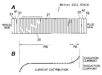
FIG. 1 is an explanatory drawing of a fuel cell stack 10 of Embodiment 1. As
shown in FIG.1 A, the fuel cell stack 10 has a cell stack 21 constituted by
stacking
in serial the prescribed number of unit cells 20 in which both surfaces of an
6
T0463 SPE3W TAN CA 02528689 2005-12-07
electrolyte membrane are sandwiched between an anode and a cathode and the
anode and cathode are sandwiched between a pair of metal separators. A pair of
terminal plates 31, 32 for taking out the power are arranged at both ends of
the cell
stack 21. The outer sides of the terminal plates 31, 32 are sandwiched by a
pair of
end plates 51, 52 via insulating plates 41, 42. An oxidation electric current
(see
FIG. 1 B) flows locally in the plus side end section in a coolant channel (not
shown
in the figure) passing through inside the cell stack 21. The oxidation current
increases rapidly in the plus side end of the cell stack 21. A metal separator
subjected to anticorrosive surface treatment is inserted in the zone PA of the
cell
stack 21 where the oxidation current flows that is equal to or higher than the
prescribed threshold, and a metal separator that is not subjected to
anticorrosive
surface treatment is inserted in the zone PB where the oxidation electric
current
flows that is less than the threshold. The threshold is preferably set to a
current
value suitable from the standpoint of both increasing the corrosion resistance
of
metal separator and reducing the cost. Because the oxidation current flows
locally
only in part of the cell stack 21, a metal separator subjected to
anticorrosive surface
treatment may be inserted at least in the zone where the oxidation current,
even if a
small one, flows.
FIG. 2 is a plan view of the metal separator 60. It is preferred that zones
that will be in contact with moisture be the portions subjected to the
anticorrosive
surface treatment. For example, the anticorrosive surface treatment may be
conducted on such portions as the coolant inlet manifold 61, a coolant outlet
manifold 62, and a cooling surface 63. Moisture that is in contact with the
metal
separator 60 is not only the coolant for cooling the unit cell 20, but also
includes a
generated water that is produced by reaction gases (fuel gas, oxidizing gas)
supplied to the unit cell 20 when they participate in the cell reaction, or
water of
7
T0463 SPE3W_TAN CA 02528689 2005-12-07
condensation that is produced, e.g., by condensation. Therefore, it is
preferred that
the anticorrosive surface treatment be also conducted on an inlet manifold, an
outlet manifold, and a gas channel for reaction gases. Furthermore, surface
treatment providing for high corrosion resistance may be conducted on the zone
of
the metal separator 60 that will be in contact with water and surface
treatment
providing for low corrosion resistance may be conducted on the zone that will
not
be in contact with water. Examples of the surface treatment providing for high
corrosion resistance include plating using noble metals such as gold and
silver and
thick-film plating. Thin-film plating is an example of surface treatment
providing for
low corrosion resistance.
According to the present embodiment, the metal separator 60 subjected to
anticorrosive surface treatment is inserted only into a zone PA where an
oxidation
current flows that is equal to or higher than the threshold. Therefore, cost
reduction
can be realized, while maintaining corrosion resistance comparable with that
attained when the anticorrosive surface treatment is conducted on all the
metal
separators 60 constituting the cell stack 21.
Embodiment 2
In the present embodiment, metal separators 60 subjected to surface
treatment providing for high corrosion resistance are inserted into zone PA
where
an oxidation current flows that is equal to or higher than the threshold, and
metal
separators 60 subjected to surface treatment providing for low corrosion
resistance
are inserted into zone PB where an oxidation current flows that is lower than
the
threshold. The degree of corrosion resistance provided by the surface
treatment
conducted on the metal separators 60 inserted in identical zone PA (or regions
PB)
8
CA 02528689 2008-10-14
may be the same, but the degree of corrosion resistance may also gradually
increase from the minus side to the plus side of the cell stack 21.
According to the present embodiment, the degree of corrosion resistance
provided by the surface treatment conducted on the metal separators 60 varies
according to the position (or amount of oxidation current) in the cell stack
21.
Therefore, cost reduction can be realized, while maintaining corrosion
resistance
comparable with that attained when the anticorrosive surface treatment is
conducted on all the metal separators 60 constituting the cell stack 21.
Mode 2 for Carrying out the Invention
FIGs. 3A and 3B are explanatory drawings of a fuel cell stack of this mode
for carrying out the invention. As shown in FIG. 3A, the fuel cell stack 11
has a cell
stack 21 constituted by stacking a plurality of unit cells 20 in which an
electrolyte
membrane is sandwiched between a pair of electrodes and the electrodes are
sandwiched between a pair of conductive separators. A fluid supply channel 71
for
supplying reaction gases (fuel gas, oxidation gas) or coolant to the unit
cells 20 and
a fluid release channel 72 for releasing the reaction gases that were supplied
to the
cell reaction of unit cells or the coolant that participated in heat exchange
with the
unit cells 20 are provided through inside the cell stack 21. A pair of
terminal plates
31, 32 for taking out the power are arranged at both ends of the cell stack
21. The
outer sides of the terminal plates 31, 32 are sandwiched by a pair of end
plates 51,
52 via insulating plates 41, 42. An inlet port 71a to the fluid supply channel
71 and
an outlet port 72a from the fluid release channel 72 are formed in the end
plate 51
on the minus side of the fuel cell stack 10.
The reaction gas supply channel and coolant supply channel, and the
9
CA 02528689 2008-10-14
reaction gas release channel and coolant release channel are respectively
different
fluid channels, but for the sake of convenience the former will be called
together a
fluid supply channel 71 and the latter will be called together a fluid release
channel
72. Furthermore, when it is not necessary to distinguish between the fluid
supply
channel 71 and fluid release channel 72, they will be simply called fluid
channels 71,
72.
A configuration may be used in which of a pair of terminal plates 31, 32, the
fluid channels 71, 72 pass through only the terminal plate 31 on the minus
side and
are communicated with the inlet port 71a and outlet port 72a and no inlet port
or
outlet port of the fluid channels 71, 72 are formed in the terminal plate 32
on the
plus side. With such a configuration, the coolant flowing through the fluid
channels
71, 72 or moisture present in the reaction gas that was generated, e.g., by
the cell
reaction is prevented from coming into contact with the terminal plate 32 of
the plus
electrode. In order to inhibit the contact of moisture with the terminal plate
32 even
more effectively, a shielding plate 80 that blocks the permeation of moisture
is
preferably disposed between the terminal plate 32 and cell stack 21. No
specific
limitation is placed on the shielding plate 80, provided that it ensures
electric
connection between the cell stack 21 and terminal plate 32 and blocks the
permeation of moisture. For example, a conductive plate is preferably used as
the
shielding plate.
As shown in FIG. 3B, a reduction current locally flows in the terminal plate
31 of the minus electrode and in the unit cell 20 in the vicinity thereof,
whereas an
oxidation current locally flows in the terminal plate 32 of the plus electrode
and in
the unit cell 20 in the vicinity thereof. Because corrosion can easily advance
if
moisture comes into contact with the terminal plate 32 of the plus electrode
where a
large oxidation current flow, when the terminal plates 31, 32 are protected
from
T0463 SPE3W_TAN CA 02528689 2005-12-07
corrosion, main attention should be paid to the plus side. Paying major
attention to
corrosion protection of the plus side, which is easier corroded, rather than
taking
identical anticorrosive measures with respect to both electrodes (plus side
and
minus side) of the fuel cell stack 10, with the above-described configuration
makes
it possible to increase corrosion resistance of the terminal plates and reduce
cost.
According to the present invention, cost reduction can be realized, while
maintaining corrosion resistance comparable with that attained when the
anticorrosive surface treatment is conducted on all the metal separators.
According to the present invention, employing a configuration in which the
coolant flowing in the fluid channels or moisture of the reaction gas are
prevented
from coming into contact with the terminal plate on the plus side enables both
the
improvement of corrosion resistance of the terminal plate and the reduction of
cost.
11