Note: Descriptions are shown in the official language in which they were submitted.
CA 02528735 2005-12-02
Description
A~aratus for the low-temperature separation of a gas
mixture, in particular air
The invention relates to an apparatus for producing a
product by low-temperature separation of a gas mixture,
in particular air, having a direct contact cooler for
IO cooling the feed mixture, having a purification
apparatus for purifying the cooled feed mixture, and
having a low-temperature part, which includes a main
heat exchanger for cooling the purified feed mixture to
approximately dewpoint temperature and a distillation
column for low-temperature separation of the feed
mixture.
Apparatuses for the low-temperature separation of air
or other gas mixtures are known, for example, from
Hausen/Linde, Tieftemperaturtechnik, [Cryogenic
Engineering], 2nd Edition, 1985.
In the present context, the term "low-temperature" is
in principle to be understood as meaning any
temperature which is below ambient temperature, but
preferably a temperature of 200 K or less, most
preferably 150 K or less, for example 100 K or less.
In a "direct contact cooler", the feed mixture is
brought into direct heat exchange with a coolant, for
example water, and thereby cooled. It is used in
particular to dissipate heat of compression which has
been produced in a feed gas compressor, generally
connected upstream.
A subsequent "purification device" is generally
designed as an adsorption apparatus and in particular
has at least two reversible vessels which are operated
cyclically. It is used to separate off undesired
CA 02528735 2005-12-02
- 2 -
components, for example those which can freeze in the
low-temperature part.
In the "low-temperature part", the feed mixture is
initially cooled to approximately dewpoint temperature
and then fractionated in a distillation column system.
The low-temperature part therefore includes one or more
heat exchangers and one or more distillation columns.
The product is extracted in gas or liquid form from the
low-temperature part. Of course, it is also possible to
produce a plurality of products in the same or
different state of aggregation and in the same or
different chemical .composition. To prevent losses
caused by ambient heat flowing in, the low-temperature
part is usually thermally insulated by being enclosed
by one or more coldboxes.
The "main heat exchanger" is used to warm the gaseous
products) in indirect heat exchange with at least one
feed mixture stream.
The three installation components mentioned are usually
arranged in such a way that the base area which they
take up is as small as possible. This is not
satisfactory in all cases.
Therefore, the invention is based on the object of
further optimizing the arrangement of the components of
a low-temperature separation unit in order to make the
unit particularly economical.
This object is achieved by virtue of the fact that the
direct contact cooler, the purification apparatus and
the low-temperature part are arranged on one line.
The arrangement "on one line" means that there must be
at least one horizontal straight line which intercepts
the base areas of all three installation components
mentioned. In the present context, the term "base area"
CA 02528735 2005-12-02
- 3 -
is to be understood as meaning the standing surface
area which is required for the corresponding
installation components including the directly
associated functional units, such as for example pumps
and fittings.
An arrangement of this type is of course - contrary to
previous practice - not optimum with regard to the
utilization of the base area of the installation as a
whole, since the base areas of the three components are
of different sizes. (In general, direct contact cooler
and purification device take up less space than the
low-temperature part.. However, in the context of the
invention it has emerged that this drawback is more
than compensated for by significant advantages.
The arrangement in one line minimizes in particular the
outlay involved in flow-connecting the components of
the installation to one another. The corresponding pipe
lengths and the size of the associated steel
structures, such as for example pipe bridges, are
minimized. This means - in particular in the case of
very large installations with a feed gas throughput of,
for example, 50 000 m3/h (s.t.p.) or more, in
particular 300 000 m3/h (s.t.p.) or more - a noticeable
reduction in investment costs.
Moreover, the linear arrangement has the advantage that
the components of the installation are in principle
accessible from both sides for installation and
maintenance work. This reduces the operating and repair
costs of the installation.
A feed gas compressor for compressing the feed mixture
is usually connected upstream of the direct contact
cooler. In the context of the invention, this may, for
example, be arranged laterally next to the group made
up of direct contact cooler, purification apparatus and
low-temperature part. However, it is particularly
CA 02528735 2005-12-02
- 4 -
expedient if the feed gas compressor, the direct
contact cooler, the purification apparatus and the
low-temperature part are arranged on one Line. This
further boosts the abovementioned advantages.
The linear arrangement of all four components of the
installation is advantageous in particular in the case
of multi-train units in which a plurality of the
apparatuses (trains) according to the invention are
arranged next to one another. In this case, different
connecting devices may be arranged at the ends of the
individual trains, for example a pipe bridge for
discharging the products on the side of the
low-temperature part and/or a gas or steam turbine for
driving the feed gas compressor with associated
accessories, such as for example an air condenser,
steam, gas and/or cooling water lines for machines or
the like, on the compressor side. Nevertheless, the
various components of the installation remain readily
accessible.
The drive shaft of the feed gas compressor in this case
in particular preferably runs substantially
perpendicular to the line on which the direct contact
cooler, the purification apparatus and the
low-temperature part are arranged.
Alternatively, the feed gas compressor may be arranged
laterally next to the remaining parts of the
installation. In this case, in particular the drive
shaft of the feed gas compressor runs substantially
parallel to the line on which the direct contact
cooler, the purification apparatus and the
low-temperature part are arranged.
Moreover, in particular in the case of mufti-train
installations, it is expedient if the base area of the
abovementioned installation components is relatively
elongate in form. More specifically, in this case the
CA 02528735 2005-12-02
- 5 -
ratio of the extent of the smallest rectangle which
encloses the base areas of the direct contact cooler,
the purification apparatus and the low-temperature part
and if appropriate the feed gas compressor, in the
direction of a connecting straight line between direct
contact cooler and low-temperature part to the extent
in the direction perpendicular to the first direction
is greater than 1, in particular greater than 1.5. By
way of example, this ratio is 2.0 or more, in
particular 3.0 or more.
A plurality of apparatuses of this type can then be
arranged longitudinally next to one another in order to
form the multi-train installation. The apparatus for
l5 connecting the individual installations to one another
(for example a pipe bridge for product lines) is
arranged along the narrow sides and can therefore be
made relatively short and inexpensive.
The feature described in Claim 5, namely the somewhat
elongate base area of the individual installation, can
in principle also be realized in apparatuses which do
not comply with the features of Claim 1.
The low-temperature part generally includes a heat
exchanger box, which contains at least one main heat
exchanger, a rectification box, which contains at least
one distillation column, and an expansion machine
arranged within a turbine casing. It is expedient if
the turbine casing is arranged at a transition section
of the low-temperature part which is located between
the heat exchanger box and the rectification box.
Alternatively, the turbine casing may be connected
directly to the heat exchanger box.
The feature described in Claim 6, namely arranging an
expansion machine at the transition section between the
heat exchanger box and the rectification box, can in
principle also be realized in apparatuses which do not
CA 02528735 2005-12-02
- 6 -
comply with the features of Claim 1.
Claims 7 to 12 give further advantageous configurations
of the apparatus according to the invention. Their
features, in an apparatus for producing a product by
low-temperature separation of a gas mixture, in
particular air, can also be used independently of the
features of Claims 1 to 6 or in combination with these
features.
The feed mixture line for introducing feed mixture into
the main heat exchanger and the product line for
extracting the product stream from the main heat
exchanger in this case run substantially parallel to a
main orientation axis and are arranged at opposite
sides of the main heat exchanger.
The "main orientation axis" represents an abstract
straight line which runs in the horizontal direction
and is generally not physically embodied by components
of the installation or any other actual device.
Two directions are "substantially parallel" if they
form an angle of less than 20°, preferably less than
10°, most preferably less than 5°, with one another.
The arrangement according to Claim 7 offers the
advantage that the devices for discharging the
products, for example one or more collection lines,
into which the product lines) opens) out, may be
arranged on one side of the main heat exchanger, and
the devices for pretreating the feed mixture may be
arranged on the opposite side of the main heat
exchanger. This allows very short pipeline lengths.
Arranging the feed mixture lines and product lines
opposite one another in particular minimizes the outlay
involved in flow-connecting the installation components
to one another . The corresponding pipe lengths and the
CA 02528735 2005-12-02
_ 7 _
size of the associated steel structures, such as for
example pipe bridges, are minimized. This means - in
particular in the case of very large installations with
a feed gas throughput of, for example, 50 000 m3/h
(s.t.p.) or more, in particular 300 000 m3/h (s.t.p.)
or more - a noticeable reduction in the investment
COStS.
The arrangement also has the advantage that the
installation components are fundamentally accessible
from both sides for assembly and repair work. This
reduces the ~operatin.g and repair costs of the
installation. '
Moreover, it is expedient if the apparatus includes a
collection line into which the product line opens out
at its end remote from the main heat exchanger and if
the collection line runs substantially perpendicular to
the main orientation axis.
A direction is "substantially perpendicular" to another
direction if the corresponding straight lines include
an angle of from 70°.to 110°, preferably 80° to
100°,
most preferably 85° to 95°.
One or more collection lines can connect the apparatus
and possible further identical or similar apparatuses
(trains) to form a multi-train installation and/or may
lead to a tank farm and/or to an emergency supply
apparatus.
The collection lines) may be arranged on a pipe bridge
or on the ground. In the latter case, the collection
lines are generally laid on what are known as sleepers.
It is preferable for collection lines) to be connected
to a product line . of one or more further
low-temperature separation apparatuses.
CA 02528735 2005-12-02
As an alternative or in addition, the collection
lines) may be connected to a storage tank for product.
It is expedient if, in the apparatus according to the
invention, the main heat exchanger is designed
exclusively as a recuperative heat exchanger, i.e. as a
non-reversible heat exchanger.
Claims 13 to Z6 give further advantageous
configurations of the apparatus according to the
invention. Their features, in an apparatus for
producing a product by low-temperature separation of a
gas mixture, in particular air, may also be used
independently of the features of Claims 1 to 12 or in
25 combination with these features.
If an evaporative cooler is used, it is expedient if
the ratio of the distance between evaporative cooler
and direct contact cooler to the distance between
evaporative cooler and main heat exchanger is at least
0.5, in particular at least 1Ø
The evaporative cooler 15 is therefore arranged
relatively close to the main heat exchanger. Although
this entails higher outlay for the coolant piping, the
line for the gas stream from the low-temperature part
can be made particularly short. In the context of the
invention, it has emerged that this arrangement overall
leads to relatively low investment costs. In
particular, the outlay on the pipelines and the
associated steelwork costs is reduced. This is
partially attributable to the very high cross section
(for example 1 to 2 m) of the gas line to the
evaporative cooler.
The dependent Patent Claims 14 to 16 give further
advantageous configurations of the apparatus according
to the invention.
CA 02528735 2005-12-02
_ g _
The invention and further details of the invention are
explained in more detail below on the basis of an
exemplary embodiment of an apparatus according to the
invention which is diagrammatically depicted in the
drawing; the apparatus is designed as a low-temperature
air separation unit.
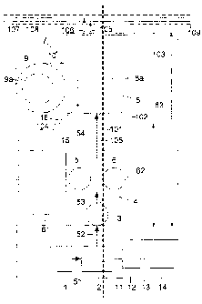
Atmospheric air as "feed mixture" is sucked in via an
inlet filter 1 and passed via feed pipelines 51, 52,
53, 54 to further components of the installation. First
of all, the filtered air 51 is compressed in a main air
compressor, which in the example constitutes the "feed
gas compressorN. The compressed air 52 flows into a
direct contact cooler 3, where it is cooled in direct
heat exchange with cooling water that flows in via a
cooling water pipe 61. The cooled air 53 is passed
onwards into a purification device 4 which includes a
pair of molecular sieve adsorbers 5, 6. The purified
air 54 flows onwards to the low-temperature part 7.
The low-temperature part may comprise a single coldbox,
in which all the cryogenic equipment is arranged, in
particular the heat exchangers) and the distillation
column(s), or alternatively a multiplicity of separate
coldboxes. In the example, there are two separate
coldboxes. A cylindrical rectification box 9 contains
the distillation columns 9a, in this case a double
column with a high-pressure column and a low-pressure
column and a main condenser arranged between them. The
remaining cold parts, in particular the main heat
exchanger 8a, are accommodated in a cuboidal heat
exchanger box 8. The two coldboxes 8, 9 insulate the
respective cold apparatus parts from ambient heat. A
transition section 10 also forms part of the
low-temperature part. It is likewise surrounded by a
coldbox; alternatively, the pipelines and fittings
located in the transition section 10 are thermally
insulated by means of a Correspondingly smaller
coldbox.
CA 02528735 2005-12-02
- 10 -
The main heat exchanger is designed as an exclusively
recuperative heat exchanger, i.e. not as a reversible
heat exchanger (Revex). It comprises, for example, one
block or a plurality of blocks which are flow-connected
to one another. The blocks) are preferably designed as
aluminium plate-type heat exchangers. Possible further
heat exchangers, such as for example one or more
supercooling countercurrent heat exchangers, may
likewise be accommodated in the heat exchanger box;
alternatively or in addition, one or more blocks of
supercooling countercurrent heat exchangers may be
arranged in the rectification box. The shape of the
rectification box may differ from the exemplary
embodiment; by way of example, it may be substantially
cuboidal.
The main air compressor 2 is driven via a first shaft
11 by a drive means 12 which is designed as an electric
motor or a gas or steam turbine. Moreover, in the
example there is a post-compressor 14 for part of the
purified air 54. The inlet of the post-compressor 14 is
connected to the pipeline 54 for the purified air via
booster air piping 62 which is only indicated in the
drawing. The air which has been compressed further in
the post-compressor 14 is passed via a further pipeline
(not shown in the drawing) into the low-temperature
part 7, in particular into the heat exchanger box 8. In
the example, the post-compressor 14 is driven via a
further shaft 13, likewise by the drive means 12.
Alternatively, the post-compressor could be driven
independently of the main air compressor, for example
by a separate gas or steam turbine or by a separate
electric motor.
The products of the low-temperature part 7 are
discharged via product lines 105, 106 which are
indicated in the drawing by way of example and in this
case open out into collection lines 107 and 108,
CA 02528735 2005-12-02
- 11 -
respectively. The collection lines I07, 108 are
arranged on a pipe bridge (109) and can connect the
apparatus and possible further identical or similar
apparatuses (trains) to form a multi-train installation
and/or lead to a tank farm and/or an emergency supply
apparatus.
An evaporative cooler 15 is used to cool water before
it is introduced into the direct contact cooler 3. In
this evaporative cooler, dry residual nitrogen from the
low-temperature part undergoes direct heat and mass
transfer with cooling water that is to be cooled. Cold
cooling water is passed to the direct contact cooler
via the cooling water piping 61. Warm cooling water is
returned directly or indirectly to the evaporative
cooler. The humid nitrogen from the evaporative cooler
escapes into the atmosphere.
The apparatus also has utility piping 63, the position
of which is diagrammatically indicated in the drawing.
The utility piping is used to transport steam, gas
and/or cooling water and to dispose of condensate,
cooling water, etc. It opens out into utility
collection lines (not shown), which may be arranged on
the pipe bridge 109. Utility and booster air piping 63,
62 may be arranged on the ground (on sleepers) or on
one or more pipe bridges.
In the exemplary embodiment, the base areas of the
direct contact cooler 3, the purification device 4 and
the low-temperature part 7 are circular or rectangular
or of a more complex shape. These base areas are
arranged on one line, for example on a main orientation
axis 101. In addition, this line 101 also runs through
the base area of the main air compressor 2. This
results in a particularly short feed gas piping 52, 53,
54. The product lines 105, 106 which are arranged
opposite the entry of the feed line 54 are also of a
particularly short length. They may even be so short
CA 02528735 2005-12-02
- 12 -
that there is no need for them to have a dedicated pipe
bridge.
The rectangle 102 which surrounds the base areas of
direct contact cooler 3, purification device 4 and
low-temperature part 7, is about a factor of 1.7 longer
in the extent which runs vertically in the drawing than
in the direction perpendicular thereto (horizontally in
the drawing). A factor of approximately 1.8 applies to
the rectangle 103 which also surrounds the base area of
the main air compressor and the equipment connected to
it. As a result, a short pipe bridge 109 and short
collection lines 10.7, 108 are sufficient for the
product discharge and the utility feed and discharge;
this is advantageous in particular in the case of
multi-train installations. (The drawing is also not
necessarily to scale in this respect, on account of its
diagrammatic nature.)
On account of their functional relationship, the direct
contact cooler 3 and evaporative cooler 15 are usually
arranged as a single unit or at least as directly
adjacent units. In the exemplary embodiment, however,
the evaporative cooler 15 is significantly closer to
the low-temperature part than to the direct contact
cooler. The distance 104 between the evaporative cooler
15 and the main heat exchanger Sa is approximately one
fifth of the distance between the direct contact cooler
3 and the low-temperature part 7. As a result, the
residual nitrogen line between the main heat exchanger
and the evaporative cooler 15, which is not illustrated
in the drawing, only has to cover a relatively short
distance and can be therefore realized at particularly
low cost; this saving is very important in view of the
very large cross section of the residual nitrogen line.
Although the cooling water piping is longer, its cross
section is very much smaller, which means that the
apparatus costs are increased only to an insignificant
extent.
CA 02528735 2005-12-02
- 13 -
Low-temperature air separation units usually have one
or more expansion machines which are used to generate
refrigeration by work-performing expansion of one or
more process streams and are usually designed as
turbines. The installation shown in the exemplary
embodiment preferably has a turbine for the
work-performing expansion of a part-stream of the feed
air or of a product or intermediate product stream from
the low-temperature separation. This turbine is
positioned in a turbine casing 16, which in the
exemplary embodiment is arranged at the transition
section 20 between heat exchanger box 8 and
rectification box 9.
CA 02528735 2005-12-02
- 13A -
Without further elaboration, it is believed that one
skilled in the art can, using the preceding description,
utilize the present invention to its fullest extent. The
preceding preferred specific embodiments are, therefore,
to be construed as merely illustrative, and not
limitative of the remainder of the disclosure in any way
whatsoever.
In the foregoing, all temperatures are set forth
uncorrected in degrees Celsius and, all parts and
percentages are by weight, unless otherwise indicated.
The entire disclosures of all applications, patents and
publications, cited herein and of corresponding European
application No. 04028682.5, filed December 3, 2004;
European application No. 04028683.3, filed December 3,
2004; and European application No. 04028681.7, filed
December 3, 2004 are incorporated by reference herein.
From the foregoing description, one skilled in the art
can easily ascertain the essential characteristics of
this invention and, without departing there from, can
make various changes and modifications of the invention
to adapt it to various usages and conditions.