Note: Descriptions are shown in the official language in which they were submitted.
CA 02528856 2005-12-09
WO 2005/002717 PCT/EP2004/005376
- 1 -
FLUID BED GRANULATION PROCESS AND APPARATUS
DESCRIPTION
Field of application
In its most general aspect, the present invention refers to
a fluid bed granulation process of an appropriate substance
like, for example, urea, ammonium nitrate, ammonium
chloride and similar substances susceptible to being
granulated.
In particular, this invention concerns a fluid bed
granulation process comprising control of the temperature
of said bed through injection therein of a flow of hot air.
The invention also refers to a granulation apparatus, used
to carry out the aforementioned process.
Prior art
It is known that in a fluid bed granulation process, the
obtainment of a predetermined substance takes place through
continuous growth (in volume and in mass), of granule seeds
of such a substance, continuously fed into said fluid bed,
at the same time with a flow of an appropriate growth
substance in liquid state.
Generally, the growth substance is of the same nature as
the substance to be granulated and is in liquid form,
suitable for wetting, adhering and solidifying on the seeds
and on the growing granules which, together, constitute
said fluid bed.
Said growth substance is fed to the fluid bed at a high
temperature so that the growth substance itself, once
CA 02528856 2005-12-09
WO 2005/002717 PCT/EP2004/005376
2
solidified on the seeds, can keep adherence characteristics
such as to allow adhesion to the granule of further growth
substance' while it is inside the fluid bed.
Moreover, inside the fluid bed it is necessary to maintain
the temperature within predetermined and, generally,
relatively high values in order to allow the evaporation of
the solvent present in the growth substance which is
generally fed in solution, for example aqueous in the case
of urea, into said fluid bed.
The temperature of the fluid bed must be chosen also taking
into account the fact that a possible cooling of the growth
substance, before its contact with the seeds and with the
growing granules, could determine a premature
solidification thereof, with consequent difficulties, if
not actually impossibility, in adhesion to the granules and
with formation of powders which require subsequent
recovering.
To satisfy the aforementioned requirement, in other words
to control and adjust the temperature of the fluid bed
within predetermined values, it has been proposed to feed,
into the granulation fluid bed itself, an additional flow
of appropriately hot air, which is preferably injected at
the same level as the flow of growth substance.
Moreover, during the start-up step, or in operation with
low loads, or else when the fluidification air, which is
used with the very high flow rates required for the
formation and maintenance of the fluid bed, is at a
particularly cold room temperature, it becomes necessary to
carry out a suitable preheating of such fluidification air
through suitable heat exchangers outside the fluid bed.
CA 02528856 2005-12-09
WO 2005/002717 PCT/EP2004/005376
3 -
Although advantageous from' some points of view, such a
suggestion suffers from a serious recognized drawback.
Indeed, due to the very high air flow rates circulating in
the fluid bed, a control of the temperature according to
the aforementioned suggestion necessarily involves very
high energy consumption for the preheating of the
fluidification air (when required) and of the additional
flow of air. This energy consumption has a negative impact
upon the operating costs of the process.
The presence of such apparatuses for preheating the air
also have a negative impact upon the embodying costs and
the structural complexity of the corresponding granulation
plant.
Summary of the invention
The technical problem underlying the present invention is
to devise and to make available a' fluid bed granulation
process of the type considered above, having functional
characteristics so as to overcome all the cited drawbacks
linked to the prior art and, in particular, such that the
total energy consumption necessary to keep the fluid bed at
a predetermined temperature which ensures the optimal
completion of the process is substantially reduced.
The-problem is solved according to the invention by a fluid
bed granulation process of an appropriate substance, with
control of the temperature of said bed, comprising a
cooling step of the finished hot granules thus obtained, in
a respective cooling fluid bed, characterized in that at
least a part of the fluidification air coming out from said
cooling fluid bed of the finished granules is fed into the
granulation fluid bed.
CA 02528856 2005-12-09
WO 2005/002717 PCT/EP2004/005376
4 -
Preferably, all of the fluidification air fed into the
granulation bed comes from the cooling bed.
Advantageously, substantially all of the fluidification air
coming out from the cooling bed is used as fluidification
air of said granulation bed.
Even more advantageously, the fluid bed granulation process
of the present invention is characterized in that it uses
one single flow of fluidification air to continuously form
and support, in order, said cooling and granulation fluid
beds, substantially arranged in series with respect to said
single flow and in fluid communication with each other.
Further characteristics and advantages of the invention
will become clearer from the detailed description of an
embodiment of a fluid bed granulation process according to
the invention, given hereafter with reference to the
attached drawings, for indicative and non-limiting
purposes.
Brief description of the figures
- figure 1 schematically shows an axonometric view of an
apparatus for carrying out the fluid bed granulation method
of the present invention;
- figure 2 schematically shows a cross section of the same
apparatus of figure 1.
Detailed description of a preferred embodiment
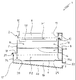
With reference to the figures, an apparatus for carrying
out a fluid bed granulation process according to the
present invention is globally indicated with 1.
CA 02528856 2005-12-09
WO 2005/002717 PCT/EP2004/005376
- 5 -
Such an apparatus comprises a self-supporting structure 2,
substantially in the shape of a parallelepiped container,
which defines a space A inside it, in which two fluid beds
F1 and F2 are intended to be realized, as can be seen more
clearly in the rest of the description.
Said container structure 2 (which hereafter shall simply be
called: container 2), has long side walls 5, 6, short front
7 (or top) and rear 8 walls; it is closed, at the top by a
conventional and therefore unrepresented cover, and it is
equipped at the bottom with a double base plate, 4, 4a,
upper and lower respectively.
In accordance with a characteristic of the present
invention, the top wall 7, of said container 2, has the
bottom side 7a, spaced from the base plate 4, of said
double base plate, with which it thus defines a passage (or
port) 20, which places the space A in communication with
the outside of said container 2. Moreover, in accordance
with another characteristic of the present invention, the
aforementioned base plates 4, 4a, extend from the rear wall
8, of the container 2, up:to past said top wall 7, for a
predetermined length portion. At their free front ends, to
a front panel 17 is fixed to the base plates 4, 4a,
preferably substantially parallel to the top wall 7, with
which it constitutes a sort of pocket 18, in the example of
the figures extending for the whole width of said wall 7
and in communication with the space A, through the
aforementioned passage 20.
The base plates 4, 4a of said double base plate, the rear
wall 8 of the container 2 and the front panel 17 define a
chamber 19 that is in fluid communication with the space A
right through said. base plate 4, provided perforated,
CA 02528856 2010-05-20
WO 200 /002717 PCT/EP20041005376
6 -
grated or in any case permeable to gas flows. Said chamber
19, extending below the space A, is of limited height and
is intended to 'constitute a chamber for uniform
distribution of a flow of fluidification air coming into
said space A, as will better turn out from the following of
the description.
Advantageously and in accordance with a further
characteristic. of the present invention, said distribution
chamber 19 has a tapered profile starting from the rear
wall 8 of the container 2, towards the front panel 17. For
such a purpose, the base plate 4a is provided tilted on the
opposite base plate 4, and converging on it towards the
aforementioned front panel 17.
Inside said container 2 a rectangular vertical panel 15 is
supported, parallel and in a predetermined spaced
relationship from the rear wall 8 of said container 2, with
which it defines an interspace 16.
Said panel 15 is fixed to the opposite long walls 5 and 6
and to the top wall 3 of said container 2, whereas it has
the horizontal bottom side 15a spaced from the base plate
4, so as to define with it a passage (or port) 25,
suitable for placing said interspace 16 in communication
with the space A inside the container itself. The
interspace 16 is in communication with the space A, also
close to the upper wall of said container 2, through an
opening 11.
Inside the container 2 and at a predetermined distance from
its base plate 4, a rectangular shelf 14 is positioned,
perimetrically fixed to the long sides 5, 6, to the front
wall 7, of said container 2 and to the aforementioned panel
CA 02528856 2005-12-09
WO 2005/002717 PCT/EP2004/005376
7 -
15. Said shelf 14, defines in said space A, a granulation
zone B inside the space A and is intended to support the
granulation bed F1 of a predetermined substance; for such a
purpose the shelf 14 is perforated, grated or in any case
made permeable to a flow of fluidification air, necessary
for the formation and maintenance of said bed Fl.
In Figure 1, a distributor device (per se known) of seeds
of granules of the substance to be granulated, positioned
in the container 2, at its top, is schematized with 10,
whereas distributor-supplier devices of. granule growth
liquid substance (also known and therefore not represented
in detail) are schematized with 12 and 13.
In Figure 2, an opening is schematized with 22, associated
with the rear wall*8, for the entry of air inside the
chamber 19. Such an opening 22 is in fluid communication
with per se known, and therefore not represented, means to
blow the air into said chamber 19.
With reference to the apparatus of figures 1 and 2, an
embodiment of the granulation process of the present
invention shall now be described.
By feeding a continuous flow of seeds of granules of a
predetermined substance and at the same time a continuous
flow of growth substance into the granulation zone B, a
granulation fluid. bed F1 is formed on the shelf 14. This
granulation bed is obtained, supported and maintained
through a continuous flow of fluidification air, fed into
the chamber 19 and from here, through the base plate 4,
into the space A, below said shelf 14. Corresponding to the
proceeding of the granulation (growth of granules) there is
an increase in the height of the fluid bed F1, until its
CA 02528856 2005-12-09
WO 2005/002717 PCT/EP2004/005376
8 -
free surface reaches the (precalculated) level of the
opening 11. At this point, through said opening 11, which
substantially acts as a weir, begins a 'continuous pouring
(or "discharge") from the bed F1 to the interspace 16, of
granules of substance which are very hot (their temperature
depends upon the temperature of the growth substance) and
above all which are finished, in other words of
predetermined grain size.
From the start of such pouring onwards the height of the
granulation bed F1 remains substantially constant.
The finished granules, continuously passed in the
interspace 16, "fall" in a substantially guided manner, or
in a cascade, on a fluid bed F2 comprising finished
granules 15 arranged' for the. starting step adjacent to the
perforated base plate 4, where they are subjected to the
aforementioned flow of fluidification air used for the bed
Fl. On such a base plate 4 a second fluid bed F2 is thus
defined, consisting exclusively of finished granules, which
extends in said space A, on said base plate 4, in the.
interspace 16 and in the pocket 18, which communicate with
said space.- .
On the free surface of the fluid bed F2 at the interspace
16 and the pocket 18 there is a lower pressure with respect
to what can be measured on the free surface of the fluid
bed F2 at the chamber A, between the walls 7 and 15; for
this reason, and since the three quoted zones are
functionally comparable to communicating vessels, the
height of the fluid bed F2 in the interspace 16 and in the
pocket 18 is greater with respect to that between the walls
7 and 15, on said base plate 4.
CA 02528856 2005-12-09
WO 2005/002717 PCT/EP2004/005376
9 -
It should be noted that the cooling fluid bed F2 is in
fluid communication with the overlying granulation bed F1
exclusively through-the shelf 14, for supporting said bed.
It should also be noted that the aforementioned interspace
16 carries out a duct function, so-called downcomer, for
the transfer of the granules from bed F1 to bed F2.
In the fluid bed F2, the hot finished granules exchange
heat with the flow of fluidification air, fed at room
temperature. While the finished granules cool down, this
air is heated by them. And this same heated air, coming out
from the fluid bed F2, is used as fluidification air of the
granulation bed F1, to which it is fed.
For such a reason, the zone of space A between said base
plate 4 and the overlying shelf 14, is known as the granule
cooling zone and, at the same time, it can be considered
the preheating zone of the fluidification air of the
granulation bed Fl.
Feeding preheated fluidification air to the granulation bed
means, on the one hand, providing the amount of air
necessary for the formation and maintenance of said fluid
bed and, on the other hand, giving to this same bed the
amount of heat necessary to decrease or even prevent
premature solidification of the growth substance and, at
the same time, to allow the evaporation of the solvent
possibly present in the growth substance fed, in solution,
into the growth fluid bed.
Using the air coming out from the granule-cooling fluid bed
as preheated fluidification air for the granulation bed
also means reducing the total air consumption to complete
the granulation process.
CA 02528856 2005-12-09
WO 2005/002717 PCT/EP2004/005376
- 10 -
The height of the fluid bed F2 (granule cooling bed and
fluidification air preheating bed) is such that its free
surface in the pocket 18 reaches the upper edge of the
front panel 17, ensuring the discharge, to the outside of
the container 2, of finished and cooled granules.
.Since the fluid bed, as is well known, has behavior totally
comparable to that of a liquid, the levels of the granules
in the pocket 18, in the interspace 16 and in the space A
are stabilized at the respective piezometric heights.
It should therefore be noted that the height of said front
panel 17, by determining the height of the fluid bed F2,
also determines the average permanency time of the finished
and hot granules in the cooling zone and, consequently,
determines both the' temperature of the finished granules
discharged from the 'container 2 and, above all, the
preheating temperature of the fluidification air.
From the start of the aforementioned "discharge" of
finished granules, the process of the present invention and
the relative apparatus are in operation.
At this point a basic characteristic of the process of the
present invention should be noted: the beds F1 and F2,
respectively for granulation and cooling of the finished
granules /preheating of fluidification air, are formed and
supported by a same flow of fluidification air, with
respect to which said beds F1 and F2 are arranged
substantially in series.
A second characteristic of the aforementioned process is
that the finished and hot granules are poured, substantially
in cascade from said granulation bed to the cooling bed.
CA 02528856 2005-12-09
WO 2005/002717 PCT/EP2004/005376
- 11 -
The main advantage achieved by the present invention
consists, as stated, of the large saving in energy
consumption with respect to what has been required up to
now to carry out fluid bed granulation processes of the
prior art, wherein a temperature control is provided
through introduction of an additional hot air flow or by
pre-heating, by means of heat exchangers, of the
fluidification air itself during predetermined situations
of the operating cycle of the granulation process. Taking
into account the considerable amounts of fluidification air
and additional hot air involved in the aforementioned
processes, the aforementioned energy saving translates into
an equally substantial reduction in the operating costs of
the process.
-15 This advantage is made possible thanks to the use of a
single flow of air for the fluidification of the cooling
bed of the finished granules and, in the order, of the
granulation bed, which involves an effective preheating of
the air subsequently fed to the latter operation.
According to a preferred 'embodiment, the front panel 17
comprises a. mobile bulkhead 21,. adjustable in height (able
to'slide vertically).
By varying the height of such a front panel 17, the height
of the second fluid bed F2 is consequently varied. This
means that, if for example the height of such a front panel
17 is increased, the height of the second fluid bed F2
increases and, consequently, the average permanency time of
the granules inside such a bed also increases.
This entails an improved heat exchange between the
aforementioned granules and the fluidification air, which
CA 02528856 2005-12-09
WO 2005/002717 PCT/EP2004/005376
- 12 -
can increase its entry temperature into the granulation bed
Fl.
The invention thus. conceived is susceptible to further
variants and modifications all of which fall within the
inventive concept and, as such, fall within the scope of
protection of the invention itself, as defined by the
following claims.
For example, the pocket 18 and the interspace 16 can be
realized with a width lower than the width of the
corresponding short front wall 7, of the panel 15
respectively.