Language selection

Search

Patent 2529144 Summary

Third-party information liability

Some of the information on this Web page has been provided by external sources. The Government of Canada is not responsible for the accuracy, reliability or currency of the information supplied by external sources. Users wishing to rely upon this information should consult directly with the source of the information. Content provided by external sources is not subject to official languages, privacy and accessibility requirements.

Claims and Abstract availability

Any discrepancies in the text and image of the Claims and Abstract are due to differing posting times. Text of the Claims and Abstract are posted:

  • At the time the application is open to public inspection;
  • At the time of issue of the patent (grant).
(12) Patent: (11) CA 2529144
(54) English Title: INSULATOR ARRANGEMENT
(54) French Title: MONTAGE D'ISOLATEUR
Status: Granted and Issued
Bibliographic Data
(51) International Patent Classification (IPC):
  • H01B 17/00 (2006.01)
  • H02G 7/04 (2006.01)
(72) Inventors :
  • ARCAND, SEBASTIEN (Canada)
(73) Owners :
  • SAINT-AUGUSTIN CANADA ELECTRIC INC.
(71) Applicants :
  • SAINT-AUGUSTIN CANADA ELECTRIC INC. (Canada)
(74) Agent: FASKEN MARTINEAU DUMOULIN LLP
(74) Associate agent:
(45) Issued: 2014-06-03
(22) Filed Date: 2005-12-09
(41) Open to Public Inspection: 2007-06-09
Examination requested: 2010-11-25
Availability of licence: N/A
Dedicated to the Public: N/A
(25) Language of filing: English

Patent Cooperation Treaty (PCT): No

(30) Application Priority Data: None

Abstracts

English Abstract

An insulator arrangement for supporting a conductor with an enclosure has an insulator fixedly connected at one end with the conductor. The insulator has another end portion mounted to a first shock absorber. The first shock absorber is further mounted with an access cover to permit displacement of the conductor and the insulator relative to the access cover. The insulator arrangement has second shock absorbers mounting the access cover to the enclosure permitting relative displacement between the access cover, which supports the insulator and conductor, and the enclosure.


French Abstract

Montage d'isolateur pour soutenir un conducteur avec enceinte et doté d'un isolateur relié de manière fixe à une extrémité du conducteur. L'isolateur est doté d'une autre extrémité installée sur un premier amortisseur de chocs. Le premier amortisseur de chocs est aussi monté avec un panneau d'accès pour permettre le déplacement du conducteur et de l'isolateur par rapport au panneau d'accès. Le montage d'isolateur a des amortisseurs de chocs secondaires pour l'installation du panneau d'accès sur l'enceinte permettant le déplacement relatif entre le panneau d'accès qui soutient l'isolateur et le conducteur, et l'enceinte.

Claims

Note: Claims are shown in the official language in which they were submitted.

What is claimed is:
1. An insulator arrangement for supporting a conductor with a
support member, the insulator arrangement comprising:
a first shock absorber; and
an insulator having a connector extending from one end portion
thereof for fixed connection with the conductor, the insulator having another
end portion mounted to the first shock absorber,
wherein the support member comprises an enclosure surrounding
the conductor, the enclosure having an access opening closed by an access
cover, the first shock absorber being mounted with the access cover to
provide displacement of the conductor and the insulator relative to the access
cover, and
wherein the insulator arrangement further comprises second shock
absorbers mounting the access cover to the enclosure and permitting relative
displacement between the access cover and the enclosure.
2. The insulator arrangement of claim 1 wherein the conductor is
cylindrical.
3. The insulator arrangement of claim 2 wherein each of the first
and second shock absorbers is one selected from the group consisting of a
resilient material and springs.
4. The insulator arrangement of claim 2 wherein the first shock
absorber is mounted at one side thereof to the insulator and at the other side
thereof to a spacer, and the spacer being affixed to the access cover.
5. The insulator arrangement of claim 1 wherein the first shock
absorber is mounted at one side thereof to the insulator and at the other side
thereof to a spacer, and the spacer being mounted to the access cover.
- 6 -

6. The insulator arrangement of claim 1 wherein the conductor
has an opening in which a retaining nut is located, and the connector
comprises a threaded stud secured with the nut.
7. The insulator arrangement of claim 6 wherein the opening in
the conductor comprises a slotted aperture along which the nut is adapted for
movement.
8. The insulator arrangement of claim 1 wherein the first shock
absorber has a first flat surface abutting the insulator and has a second
opposing flat surface abutting a spacer, the spacer being affixed to the
access
cover.
9. The insulator arrangement of claim 1 wherein the enclosure
further has a pair of opposing in-turned flanges at the access opening and the
second shock absorbers abut respective in-turned flanges, the access cover
abutting the second shock absorbers, bolts passing through the in-turned
flanges to mount the second shock absorbers to the enclosure and the access
cover.
10. An insulator arrangement for supporting a conductor,
comprising:
a support member comprising an enclosure surrounding the
conductor, the enclosure having an access opening;
an access cover for closing the access opening;
a first shock absorber supported by the access cover;
an insulator supported by the first shock absorber; and
second shock absorbers mounting the access cover to the enclosure
and permitting relative displacement between the access cover and the
enclosure,
wherein the conductor is supported by the insulator so that the
conductor is displaceable relative to the access cover.
- 7 -

11. The insulator arrangement of claim 10 wherein the conductor
is cylindrical.
12. The insulator arrangement of claim 11, further comprising a
spacer affixed to the access cover, the first shock absorber being mounted at
one side thereof to the insulator and at the other side thereof to the spacer.
13. The insulator arrangement of claim 12 wherein each of the
first shock absorber and the second shock absorbers comprises a resilient
material or a spring.
14. The insulator arrangement of claim 10, further comprising a
spacer affixed to the access cover, the first shock absorber being mounted at
one side thereof to the insulator and at the other side thereof to the spacer.
15. The insulator arrangement of claim 10 wherein the enclosure
further has a pair of opposing in-turned flanges at the access opening and the
second shock absorbers abut respective in-turned flanges, the access cover
abutting the second shock absorbers, bolts passing through the in-turned
flanges to mount the second shock absorbers to the enclosure and the access
cover.
- 8 -

Description

Note: Descriptions are shown in the official language in which they were submitted.


CA 02529144 2005-12-09
178753
- 1 -
INSULATOR ARRANGEMENT
Field of the Invention
The present invention relates to an insulator arrangement suitable for
use in isolated phase bus duct for supporting a conductor relative to a bus
duct enclosure.
Background of the Invention
Insulators currently used for supporting a conductor within an
enclosure, such as, for example, isolated phase bus duct, are supported by
an aluminum plate that is in turn bolted to wings welded to the inside of the
enclosure. The conductor is mounted to the insulator by a bolt that passes
through the conductor and the central axis of the conductor. In the event of a
short-circuit condition, a force is applied to the conductor of each phase of
the
bus ducts that tries to move the conductor to a zero force line. Because the
insulators are typically made from ceramic compositions, they are less able to
withstand the shearing action associated with the movement to the zero force
line than the compressive load to which the insulators are normally subjected.
These forces are greater than those that can be compensated for by any
inherent flexibility in the aluminum plate to which the insulator is mounted.
As
a result, mechanical force formulas have been developed to determine the
maximum span or distance between insulators along each bus duct run. For
high short-circuit requirements, the span between insulators is relatively
small

CA 02529144 2005-12-09
178753
so as to maintain the conductor in place and prevent the conductor from
moving to the zero force position and potentially damaging the insulators.
This results in a rather expensive bus duct configuration using many
insulators.
U.S. patent 2,396,131 issued to Scott, Jr. discloses a bus bar support
where insulators are provided with a universal ball and socket type joint to
compensate for movement of the conductor relative to the enclosure due to
thermal expansion and contraction of the conductor. However, this patent
discloses four such insulators for each connection point with the enclosure.
Hence many insulators are required giving rise to an expensive bus duct
configuration. Further, the insulator is reinforced at the universal joint
with a
steel bearing sleeve threaded into the insulator that nests in the insulator a
spring washer to provide the socket portion of the universal joint. This
configuration is costly to manufacture.
Accordingly, there is a need for an insulator arrangement that
addresses forces associated with short-circuit conditions and the stress
placed on the insulator during such short-circuit conditions.
Brief Description of the Invention
The present invention relates to an insulator arrangement for
supporting a conductor with a support member. The insulator arrangement
comprises an insulator having a connector extending from one end portion
thereof for fixed connection with the conductor. The insulator has another
end portion mounted to a first shock absorber. The first shock absorber is
further mounted with the support member to permit displacement of the
conductor and the insulator relative to the support member.
The first shock absorber permits the insulator to move when the
conductor moves towards the zero force position in the event of short-circuit
conditions thereby reducing the stress requirements of the insulator. As a
result, fewer insulators are required to mount the conductor relative to the
support member.
- 2 -

CA 02529144 2010-11-25
178753
IP =
In one embodiment the conductor is cylindrical and the support
member comprises an enclosure surrounding the cylindrical conductor, such
as for example, an isolated phase bus duct. The support member further
comprises an access opening closed by an access cover. The first shock
absorber is mounted with the access cover to provide displacement of the
conductor and the insulator relative to the access cover. The insulator
arrangement further comprises second shock absorbers mounting the access
cover to the enclosure and permitting relative displacement between the
access cover and the enclosure.
By utilizing first and second shock absorbers, the stress placed on the
insulators is further reduced over the use of only the first shock absorber.
Brief Description of the Drawings
For a better understanding of the nature of the present invention
reference may be had by way of example to the accompanying diagrammatic
drawings in which:
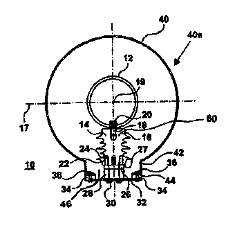
Figure 1 is a side view of an embodiment of the insulator arrangement
for the present invention;
Figure 2 is a view of a portion of the conductor having a circular
aperture;
Figure 3 is a view of a portion of the conductor having a slotted
aperture; and
Figure 4 is a view of another bus duct embodiment utilizing two
insulator arrangements
Detailed Description of the Invention
The present invention relates to an insulator arrangement suitable for
use in isolated phase bus duct for supporting a conductor relative to a bus
duct enclosure.
Referring to Figure 1, there is shown an insulator
arrangement 10 for supporting a cylindrical conductor 12 relative to a
bus duct support member 40a including an enclosure 40 that surrounds
the conductor 12. The conductor 12 is mounted in a manner
which allows it to move towards a zero force position either to the
-3...

CA 02529144 2005-12-09
178753
left or right along line 17 or along the axis 19 of the conductor 12. The
conductor in this arrangement is also capable of limited vertical movement.
The mounting provided by the insulator arrangement comprises an insulator
14 having one end 60 journalled with a threaded stud 18 that is threaded into
a nut 20 secured on an inside wall surface of conductor 12. The threaded
stud 18 passes through either an opening 100 in conductor 12, as shown in
Figure 2, or slotted opening 102 as shown in Figure 3. The opening 100
provides for a fixed insulator arrangement whereas the opening 102 provides
for a slip insulator arrangement relative to the conductor 12.
The other end 22 of the insulator 14 is secured by bolt 24 to a shock
absorber 26 and a spacer 28. The spacer 28 is in turn affixed by bolts 30 and
access cover 32 such that cover 32 supports the conductor 12 and insulator
14 with the enclosure 40. The shock absorber 26 is a first or interior shock
absorber that may comprise a flexible material such as silicone or
alternatively an assembly of a set of springs mounted between plates. The
shock absorber 26 permits for relative movement of both the conductor 12
and insulator 14 relative to the access cover 32 and hence the enclosure 40.
The spacer 28 is utilized to gauge the distance between the access cover 32
and the conductor 12. As shown in this embodiment the shock absorber 26
has a relatively flat surface 27 that abuts against insulator 14 and does not
penetrate the insulator 14. The shock absorber 26 also abuts against the
spacer 28.
The enclosure 40 surrounds the conductor 12 and has a cylindrical
wall 42 that define an access opening 46. The access opening 46 is closed
by access cover 32. The cylindrical wall 42 has in-turned flanges 44. A
second shock absorber arrangement in the form of two shock absorbers 34
are mounted between the access cover 32 and the in-turned flanges 44 of the
enclosure 40 in abutting relation therewith. The access cover 32, shock
absorbers 34 are mounted relative to the in-turned flanges 44 of the
enclosure 40 by means of bolts and nuts 36. The second or exterior shock
absorbers 34 comprise the same material or construction as that for the first
- 4 -

CA 02529144 2013-08-08
.178753
shock absorber 26. The second shock absorbers 34 permit for the relative
movement of the insulator 14 and conductor 12 relative to the enclosure 40
due to the relative movement permitted between the access cover 32 and the
enclosure 40.
The first shock absorber 26 permits the insulator 14 to move when the
conductor 12 moves towards the zero force position in the event of short-
circuit conditions thereby reducing the stress requirements of the insulator
14.
The second shock absorbers 34 permit relative movement between the
access cover 32 and the enclosure 40 and hence the second shock absorbers
34 further reduce the stress placed on the insulator 14.
Referring to FIG. 4, there is shown an embodiment for a larger sized
conductor 12 in a bus duct enclosure 40. In this embodiment two insulator
arrangements 10 are shown offset from vertical axis 140 by 45 degrees where
each insulator 14 is offset from each other by 90 degrees. Two insulators 14
are utilized due to the size of the increased conductor 12 and associated
currents that pass there along. All other features of the insulator
arrangements
are similar to those described for Figures 1 to 3.
While there have been described herein what are considered to be
preferred and exemplary embodiments of the present invention, other
modifications of these embodiments falling within the invention described
herein shall be apparent to those skilled in the art.
- 5 -

Representative Drawing
A single figure which represents the drawing illustrating the invention.
Administrative Status

2024-08-01:As part of the Next Generation Patents (NGP) transition, the Canadian Patents Database (CPD) now contains a more detailed Event History, which replicates the Event Log of our new back-office solution.

Please note that "Inactive:" events refers to events no longer in use in our new back-office solution.

For a clearer understanding of the status of the application/patent presented on this page, the site Disclaimer , as well as the definitions for Patent , Event History , Maintenance Fee  and Payment History  should be consulted.

Event History

Description Date
Revocation of Agent Requirements Determined Compliant 2022-05-06
Appointment of Agent Requirements Determined Compliant 2022-05-06
Revocation of Agent Request 2022-05-06
Appointment of Agent Request 2022-05-06
Inactive: Correspondence - Transfer 2022-03-29
Inactive: Recording certificate (Transfer) 2021-12-20
Change of Address or Method of Correspondence Request Received 2021-12-03
Inactive: Single transfer 2021-12-03
Common Representative Appointed 2019-10-30
Inactive: Late MF processed 2016-02-01
Letter Sent 2015-12-09
Grant by Issuance 2014-06-03
Inactive: Cover page published 2014-06-02
Pre-grant 2014-03-13
Inactive: Final fee received 2014-03-13
Notice of Allowance is Issued 2013-09-23
Letter Sent 2013-09-23
Inactive: Approved for allowance (AFA) 2013-09-19
Amendment Received - Voluntary Amendment 2013-08-08
Inactive: S.30(2) Rules - Examiner requisition 2013-02-19
Letter Sent 2010-12-09
Amendment Received - Voluntary Amendment 2010-11-25
Request for Examination Requirements Determined Compliant 2010-11-25
All Requirements for Examination Determined Compliant 2010-11-25
Request for Examination Received 2010-11-25
Application Published (Open to Public Inspection) 2007-06-09
Inactive: Cover page published 2007-06-08
Inactive: IPC assigned 2006-02-21
Inactive: First IPC assigned 2006-02-21
Inactive: IPC removed 2006-02-21
Inactive: IPC assigned 2006-02-21
Letter Sent 2006-01-20
Filing Requirements Determined Compliant 2006-01-20
Inactive: Filing certificate - No RFE (English) 2006-01-20
Application Received - Regular National 2006-01-20

Abandonment History

There is no abandonment history.

Maintenance Fee

The last payment was received on 2013-11-19

Note : If the full payment has not been received on or before the date indicated, a further fee may be required which may be one of the following

  • the reinstatement fee;
  • the late payment fee; or
  • additional fee to reverse deemed expiry.

Please refer to the CIPO Patent Fees web page to see all current fee amounts.

Owners on Record

Note: Records showing the ownership history in alphabetical order.

Current Owners on Record
SAINT-AUGUSTIN CANADA ELECTRIC INC.
Past Owners on Record
SEBASTIEN ARCAND
Past Owners that do not appear in the "Owners on Record" listing will appear in other documentation within the application.
Documents

To view selected files, please enter reCAPTCHA code :


To view images, click a link in the Document Description column. To download the documents, select one or more checkboxes in the first column and then click the "Download Selected in PDF format (Zip Archive)" or the "Download Selected as Single PDF" button.

List of published and non-published patent-specific documents on the CPD .

If you have any difficulty accessing content, you can call the Client Service Centre at 1-866-997-1936 or send them an e-mail at CIPO Client Service Centre.


Document
Description 
Date
(yyyy-mm-dd) 
Number of pages   Size of Image (KB) 
Claims 2005-12-09 2 67
Description 2005-12-09 5 215
Abstract 2005-12-09 1 17
Drawings 2005-12-09 2 36
Representative drawing 2007-05-15 1 10
Cover Page 2007-06-05 1 36
Drawings 2010-11-25 2 35
Description 2010-11-25 5 217
Description 2013-08-08 5 216
Claims 2013-08-08 3 98
Representative drawing 2014-05-07 1 9
Cover Page 2014-05-07 2 38
Courtesy - Certificate of registration (related document(s)) 2006-01-20 1 104
Filing Certificate (English) 2006-01-20 1 157
Reminder of maintenance fee due 2007-08-13 1 112
Reminder - Request for Examination 2010-08-10 1 120
Acknowledgement of Request for Examination 2010-12-09 1 176
Commissioner's Notice - Application Found Allowable 2013-09-23 1 163
Maintenance Fee Notice 2016-01-20 1 170
Late Payment Acknowledgement 2016-02-01 1 163
Courtesy - Certificate of Recordal (Transfer) 2021-12-20 1 403
Correspondence 2014-03-13 1 35
Change to the Method of Correspondence 2021-12-03 4 164