Note: Descriptions are shown in the official language in which they were submitted.
CA 02529184 2005-12-06
HYDROSTATIC WORKPIECE HOLDER
WITH A REMOVABLE CARTRIDGE ASSEMBLY
Field of the Invention
[0001] The present invention relates to machine tools and, more specifically,
to a
hydrostatic workpiece holder.
Background of the Invention
[0002] Hydrostatic workpiece holders utilize hydrostatic pressure to expand a
metal
sleeve, which exerts a holding pressure on a workpiece. U.S. Patent No.
6,015,154 discloses
a hydrostatic holding device comprising a fluid chamber defined, at least in
part, by a bladder
or bladder. The bladder separates the fluid in the chamber from the sleeve and
prevents the
fluid in the chamber from escaping. While the device is effective and reliable
as a workpiece
holder, improvements are necessary to reduce leakage from the fluid chamber
and further to
increase the performance and durability of the device.
Summary of the Invention
[0003] The present invention provides a hydrostatic workpiece holding
apparatus
comprising a body, a cartridge assembly carried by the body and a sleeve. The
cartridge
assembly comprises a bladder, a retainer supporting the bladder, a fluid
chamber that houses
a fluid, at least one sealing member and at least one annular seal between the
bladder and the
sealing member(s). Each annular seal corresponds with one sealing member,
where the
sealing member engages the bladder by force exerted on the annular seals) and
the bladder
from adjusting the sealing member. A seal is formed between the sealing
members) and the
bladder that prevents the fluid from escaping the fluid chamber. When the
fluid is
1
CA 02529184 2005-12-06
pressurized, a radial force is exerted against the bladder to force the sleeve
into firm and
frictional engagement with a workpiece. The workpiece is then ready for
machining or other
similar workpiece treatment processes.
[0004] In a first embodiment of the present invention, the workpiece holder is
a
hydrostatic chuck comprising a body, a sleeve and a first design of a
cartridge assembly. The
cartridge assembly comprises a bladder, a retainer supporting the bladder, a
fluid chamber for
housing a fluid, at least one sealing member and at least one annular seal
between the bladder
and the sealing member(s). The sealing members) comprises a transversely
extending leg
portion that contacts the annular seals) and a body portion that has a
threaded end for joining
the sealing members together. When the sealing members are joined together and
tightened,
axial force is exerted on the bladder, whereby the sealing members) engages
the annular
seals) causing the annular seals) to flatten. Seals are, thus, created between
the sealing
members) and the bladder to prevent fluid from escaping the fluid chamber. The
cartridge
assembly of the first embodiment of the present invention is configured to
exert a radially
inward force against the sleeve of the hydrostatic chuck for firm, frictional
engagement of the
sleeve with a workpiece.
[0005] In a second embodiment of the present invention, the workpiece holder
is a
hydrostatic chuck comprising a second design of a cartridge assembly. The
cartridge
assembly comprises a bladder, a retainer supporting the bladder, a fluid
chamber for housing
a fluid, at least one sealing member, at least one annular seal between the
bladder and the
sealing member(s), at least one end plate, at least one fastener and at least
one set screw. In
this design of the cartridge assembly, the sealing members) is an annular
plate, adjustably
incorporated within the cartridge assembly between the annular seals) and the
end plates)
by the set screw(s). When the set screws) is tightened, axial force is exerted
on the sealing
members) and, thus, exerted on the annular seal(s). Then, the sealing members)
engages the
2
CA 02529184 2005-12-06
annular seals) causing the annular seals) to flatten. Seals are, thus, created
between the
sealing members) and the bladder to prevent fluid from escaping the fluid
chamber. Like
that of the first embodiment, the cartridge assembly of the second embodiment
is also
configured to exert a radially inward force against the sleeve of the
hydrostatic chuck for
firm, frictional engagement of the sleeve with a workpiece.
[0006] In a third embodiment of the present invention, the workpiece holding
apparatus is a hydrostatic arbor comprising a body, a sleeve and a cartridge
assembly that is
substantially similar to the first design of the cartridge assembly of the
first embodiment. In
the arbor design of the third embodiment, the cartridge assembly is configured
to exert a
radially outward force against the sleeve of the arbor for firm, frictional
engagement of the
sleeve with a workpiece.
[0007] In a fourth embodiment of the present invention, the workpiece holding
apparatus is a hydrostatic arbor comprising a cartridge assembly that is
substantially similar
to the second design of the cartridge assembly of the second embodiment.
Again, as in the
third embodiment, the second design of the cartridge assembly for the fourth
embodiment is
configured to exert a radially outward force against the sleeve of the arbor
for firm, frictional
engagement of the sleeve with a workpiece.
(0008] Objects, features and advantages of this invention include providing a
reliable
and economical workpiece holder that further reduces the extent of leakage of
pressurized
fluid from the fluid chamber through the sleeve of the holder, thereby
permitting repeated and
long-lasting use of the workpiece holder for continuous machining of various
tubular
workpieces.
3
CA 02529184 2005-12-06
Brief Descriution of the Drawings
[0009] These and other objects, features and advantages of this invention will
be
apparent from the following detailed description of the preferred embodiments
and best
mode, appended claims and accompanying drawings in which:
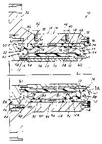
[0010] FIG. 1 is a cross-sectional view of a hydrostatic chuck including a
cartridge
assembly according to a first exemplary embodiment of the present invention;
[0011] FIG. 1A is fragmentary section of the cartridge assembly of FIG. 1
showing
construction of a bladder prior to engagement by a sealing member;
[0012] FIG. 2 is a fragmentary section of the cartridge assembly of FIG. 1
showing
an alternative configuration of an annular seal between the bladder and the
sealing member;
[0013] FIG. 3 is a cross-sectional view of a hydrostatic chuck including a
cartridge
assembly according to a second exemplary embodiment of the present invention;
(0014] FIG. 4 is a cross-sectional view of a hydrostatic arbor including a
cartridge
assembly according to a third exemplary embodiment of the present invention;
and
[0015] FIG. 5 is a cross-sectional view of a hydrostatic arbor including a
cartridge
assembly according to a fourth exemplary embodiment of the present invention.
Detailed Description of the Preferred Embodiments
I. Hydrostatic Chuck Design
First Embodiment
[0016] Referring in more detail to the drawings, FIG. 1 illustrates a
hydrostatic
workpiece holder, and more specifically, a hydrostatic chuck 10 constructed to
firmly hold
and accurately locate a tubular workpiece 12 received therein, such as a cast
iron cylinder
sleeve for an engine. The chuck 10 includes a body 14, a tubular metal sleeve
16 and a first
design of a removable cartridge assembly 18 that is carried by the body 14
between the body
4
CA 02529184 2005-12-06
14 and the sleeve 16. The cartridge assembly 18 is a self contained unit that
may be
assembled to the holder 10 as a separate sub-assembly. The cartridge assembly
18 comprises
a retainer 20, two annular sealing members 22, 24 adjustably threaded
together, a polymeric
member, cylinder, bladder, or ring 28, various shown o-rings, and a fluid
chamber 30. The
fluid chamber 30 is defined, at least in part, by the bladder 28 and the
retainer 20 and receives
a fluid therein which can be pressurized. The pressurized fluid is retained
within the fluid
chamber 30 by a fluid-tight sealing arrangement formed between the sealing
members 22, 24
and the bladder 28. Such seals are created by tightening the threadedly joined
sealing
members 22, 24 so that the sealing members 22, 24 engage annular seals 26, 27
positioned at
axial ends of the bladder 28. When the fluid within the fluid chamber 30 is
pressurized, a
radial force is exerted on the metal sleeve 16, which is urged radially inward
into engagement
with the workpiece 12.
[0017] A representative workpiece 12 is a cast iron sleeve, such as a cylinder
liner for
an internal combustion engine. Typically, a plurality of cast metal workpieces
of the same
design have relatively rough surfaces and significant variations in inside and
outside diameter
and hence, a large displacement of the metal sleeve 16 is needed to firmly
hold and
accurately locate on center, one at a time, each of a plurality of workpieces
12 on the chuck
as they are machined.
[0018] As shown in FIG. 1, the chuck body 14 of the chuck 10 includes a
radially
extending flange 32 constructed to be attached to a machine spindle for co-
rotation therewith.
The body 14 has a generally cylindrical sidewall 34 with a through bore 36 and
a pair of fluid
passages 38, 40 through which fluid is supplied to the fluid chamber 30.
Preferably, as
shown in phantom in FIG. 1, a threaded screw 42 received in each fluid passage
38, 40
provides a piston which can be advanced or retracted by rotation of the screw
to apply direct
pressure on the fluid in the fluid chamber 30. Alternatively, a pair of
pressurized fluid supply
5
CA 02529184 2005-12-06
tubes or pistons (not shown) may communicate with each fluid passage 38, 40 to
supply fluid
under pressure to the fluid chamber 30. A counterbore 44 formed in the body 14
receives a
stop ring 46, which is attached to the body 14 by a plurality of spaced apart
cap screws
received through holes 48 in a radially extending flange 50 of the stop ring
46. The stop ring
46 has an annular wall 52 extending into the bore 36 and constructed to
provide a stop
surface 54 which abuts the workpiece 12 to locate the workpiece 12 within the
chuck 10.
Alternatively, the workpiece 12 can be located by air registration or other
suitable means.
[0019] The workpiece 12 is held in the chuck body 14 by the metal sleeve 16.
The
metal sleeve 16 is an expandable sleeve, which is preferably a split-sleeve or
collet. The
expandable sleeve 16 includes longitudinally extending slits (not shown)
spaced about the
circumference of the sleeve 16 to facilitate radial displacement of the sleeve
16. In any case,
the metal sleeve 16 is preferably flexible enough to conform to and center an
out-of round
workpiece 12 so that workpiece 12 can be machined into a true round condition.
The metal
sleeve 16 further includes a body portion 56 with equally circumferentially
spaced apart tabs
58, 60 extending from opposed ends of the body 56 to allow the sleeve 16 to be
located and
retained within the chuck body 14. The tabs 58, 60 each comprise castellations
that are
slidably received in complementary mating recesses or castellations formed in
stop ring 46
and an annular nose cap 110 respectively. The design of the nose cap 110 will
later be
described in more detail. Spacer rings 62, 64 are disposed adjacent to the
stop ring 46 and the
nose cap 110 and are used to accurately locate and center the metal sleeve 16.
[0020] The bladder 28 of the cartridge assembly 18 is generally U-shaped in
longitudinal cross section and is made of a rubber material. The rubber
material is preferably
a substantially 70 durometer material on the Shore A scale, such as a
polyurethane, silicone,
buty-n, butyl-n, or other suitable material known to one skilled in the art.
For purposes of the
present invention, the bladder 28 is circumferentially continuous and can be a
hollow
6
CA 02529184 2005-12-06
cylindrical member, ring, or other similar configuration. The bladder 28 has
inwardly
extending flanges 66, 68 to which outwardly extending shoulders 70, 72 of the
retainer 20 are
received. The space or gap left between the bladder 28 and the retainer 20
defines the fluid
chamber 30. As shown in FIG. l, the annular seals 26, 27 are protuberances
that are
integrally formed on the axial ends of the bladder 28. The protuberances are
preferably
flexible annular bulges of a relatively resilient bladder material that are
compressed into
sealing engagement with the annular sealing members 22, 24 by pressurized
fluid in the
chamber 30 and expand when engaged by a hard surface, thereby forming a fluid-
tight seal.
The compression of the annular seals 26, 27 will be discussed later in
conjunction with FIG.
1 A. Alternatively, as shown in FIG. 2, the annular seals 26, 27 may be
provided as o-rings
71 that are disposed within annular grooves 73 formed in the sealing member
24. The o-ring
71 is compressed into sealing engagement with a flat surface of the bladder 28
by pressurized
fluid in the chamber 30 and expand when engaged by a harder surface, thereby
forming a
fluid tight seal between the bladder 28 and the sealing member 24. An annular
groove is also
formed in the sealing member 22 to receive an o-ring, which is not shown in
FIG. 2.
[0021] With reference again to FIG. 1, the retainer 20 is a generally circular
annular
body, or other similar construction, with two radial passages 74, 76 that
communicate with
the radial passages 38, 40 of the chuck body 14 to thereby allow the
pressurized fluid to pass
through the retainer 20 and into the fluid chamber 30. Fluid is prevented from
escaping the
fluid chamber 30 through the radial passages 74, 76 of the retainer 20 by a
pair of spaced
apart grooves 78, 80 and 82, 84 formed in the retainer 20 surrounding each
radial passage 74,
76. The grooves 78, 80, 82, 84 are constructed to receive a seal, such as an o-
ring. To
receive the annular axial flanges 66, 68 of the retainer has complementary
shoulders in its
opposed axial ends.
7
CA 02529184 2005-12-06
[0022] The threaded sealing members 22, 24 of the cartridge assembly 18 of the
first
embodiment of the present invention are constructed to engage the annular
seals 26, 27, each
forming a fluid-tight seal to prevent fluid from leaking from the fluid
chamber 30 through the
metal sleeve 16. Each sealing member 22, 24 is "L"-shaped and comprises a
transversely
situated leg section 86, 88 and a longitudinally situated body section 90, 92
respectively. The
leg sections 86, 88 are constructed of a relatively hard material such as
steel or aluminum that
engages the protuberances 26, 27 of the bladder 28 as shown in FIG. 1. The
body sections
90, 92 comprise overlapping complementary threaded end portions 94, 96 that
allow the
sealing members 22, 24 to be axially joined together. Depending upon the
desired tightness
of the seals formed between the sealing members 22, 24 and the bladder 28, the
axial spacing
between the legs 86, 88 of the joined sealing members 22, 24 can be adjusted
by changing the
extent to which the ends 94, 96 are threaded together. The body sections 90,
92 of the sealing
members 22, 24 further comprise radial passages 98, 99 that communicate with
the radial
passages 38, 40 of the chuck body and the radial passages 74, 76 of the
retainer 20 to allow
the pressurized fluid to pass through to the fluid chamber 30. Located on
either side of the
radial passages 98, 99 are grooves 100, 102, 104, 106 that are constructed to
receive an
elastomeric seal, such as an o-ring. The o-ring prevents fluid from escaping
from the fluid
chamber through the radial passages 98, 99. Alternatively, fluid ports may be
provided in the
flange 32 to allow pressurized fluid to pass through to the fluid chamber 30.
[0023] The seals formed between the sealing members 22, 24 and the bladder 28
will
now be described in more detailed with reference to FIGS. 1 and 1 A. FIG. 1 A
depicts a
portion of the cartridge assembly 18 of FIG. 1 (circle 1 A) prior to
tightening the threaded
ends 92, 94 of the sealing members 22, 24. Here the annular seal 27, which is
a
protuberance as shown in FIGS. 1 and 1 A, is shown fully formed in its relaxed
"bulged"
state. The leg section 88 of the sealing member 24 is positioned substantially
away from the
8
CA 02529184 2005-12-06
protuberance 27, thereby exposing a gap 108 between them. The gap 108 is an
easy access
route for the fluid to escape from the fluid chamber 30 to the metal sleeve 16
and, thus, must
be sealed. Referring now to circle 1A in FIG. l, when the sealing members 22,
24 are further
threaded together, the leg 88 engages the protuberance 27 and exerts an axial
force on the
protuberance 27, which forces the protuberance 27 to be compressed and
flattened against the
hard surface of the leg section 88, thereby closing the gap 108 (of FIG. 1 A).
When the
protuberance 27 is axially compressed by the leg section 88, the flange 66 of
the bladder 28
will also be radially compressed thereby further sealing any spacing (not
shown) between the
retainer 20 and the sealing member 24. The more force exerted on the
protuberance 27, the
tighter the seal between the sealing member 24 and the bladder 28 and between
the flange 66
and the retainer 20 and member 24. The same holds true for achieving a fluid-
tight seal
between the sealing member 22 and the bladder 28 and between the flange 68 and
the retainer
20 and member 22.
[0024] To assemble the chuck 10, the spacer ring 62 is received within the
bore 36 of
the body 14 abutting the flange 50 of the stop ring 46. The seals formed
between the sealing
members 22, 24 and the bladder 28 are preferably pre-set and then the
cartridge assembly 18
is inserted into the bore 36 in abutting relationship to the spacer ring 62.
Then the spacer
ring 64 is placed in abutting relationship to the cartridge assembly 28. The
annular nose cap
110 is attached to the chuck body 14 by cap screws received through holes 112
in the nose
cap 110 and threaded into blind bores 114 in the chuck body 14. The nose cap
110 overlaps
and retains the spacer ring 64 in the chuck body 14. The nose cap 110 also
retains the metal
sleeve 16 within the chuck 10.
(0025] In use, the workpiece 12 is received within the metal sleeve 16 with
one end
abutting the stop surface 54 of the stop ring 46 (or located by air
registration). To firmly hold
and accurately locate the workpiece 12 within the chuck 10, a substantially
incompressible
9
CA 02529184 2005-12-06
fluid is preferably pressurized by manually advancing the screw 42 so that the
fluid flows to
the fluid passages 38, 40 of the chuck body 14, through the radial passages
98, 99 of the
sealing members 22, 24 and through the radial passages 74, 76 of the retainer
20 to provide
pressurized fluid in the fluid chamber 30. The pressurized fluid is preferably
a viscous liquid
such as oil, water, or the like, but may be any material including a grease.
The pressurized
fluid produces a radial force urging the bladder 28 into engagement with the
metal sleeve 16.
The force acting on the metal sleeve 16 displaces or contracts the metal
sleeve 16 and urges
the sleeve 16 radially inward into firm and frictional engagement with the
workpiece 12 to
firmly hold and accurately locate the workpiece 12 so that its inner surface
may then be
machined.
Second Embodiment
(0026] FIG. 3 provides a hydrostatic chuck 200 comprising a chuck body 214
having
a tubular metal sleeve 216 and a second design of a cartridge assembly 218.
The designs of
the chuck body 214 and the metal sleeve 216 are the same as that described for
the first
embodiment except that the chuck body 214 comprises a single fluid passage 206
controlled
by a threaded screw 208 to supply fluid under pressure from an external source
to the fluid
chamber 230. In the second design of the cartridge assembly as shown in FIG.
3, more than
one fluid passage 206 can be incorporated to supply pressurized fluid to the
fluid chamber
230.
(0027) The removable cartridge assembly 218 comprises a retainer 220, two
sealing
plate members 222, 224, a bladder 228, a fluid chamber 230, end plates 246,
248, fasteners
262, 264 and set screws 202, 204. Like that of the cartridge assembly 18 of
the first
embodiment, the cartridge assembly 218 is a self contained unit that may be
assembled to the
holder 200 as a separate sub-assembly. The fluid chamber 230 is defined, at
least in part, by
CA 02529184 2005-12-06
the bladder 228 and the retainer 220 and receives a pressurized fluid. The
pressurized fluid is
retained within the fluid chamber 230 by a fluid-tight sealing arrangement
formed between
the sealing plates 222, 224 and the bladder 228 by adjusting the sealing
plates axial spacing
between the sealing plates 222, 224 by advancing a plurality of equally
circumferentially
spaced apart set screws 202, 204 so that the sealing plates 222, 224 engage
annular seals 226,
227 shown as protuberances formed on axial ends of the bladders 228. When the
fluid
chamber 230 is filled with the pressurized fluid, a force is exerted on the
metal sleeve 216,
which expands into engagement with a workpiece 212.
[0028] As shown in FIG. 3, the bladder 228 is generally U-shaped in cross-
section
and comprises inwardly extending flanges 232, 234 to which outwardly extending
shoulders
236, 238 of the retainer 220 are received. The space between the bladder 228
and the retainer
220 defines the fluid chamber 230. The annular seals 226, 227 shown as
protuberances in
FIG. 3 are integrally formed on axial ends of the bladder 228. The
protuberances 226, 227
are flexible bulges of bladder material that are resiliently compressed when
engaged by the
sealing plates 222, 224, thereby forming a fluid-tight seal therebetween.
Alternatively, the
annular seals 226, 227 may be provided as o-rings disposed within annular
grooves formed in
the sealing members 222, 224.
[0029] The retainer 220 comprises a radial passage 240 that communicates with
the
radial passage 206 of the chuck body 214. The radial passage 240 allows the
pressurized
fluid to pass through the retainer 220 and into the fluid chamber 230. Fluid
is prevented from
escaping the fluid chamber 230 through the radial passage 240 of the retainer
220 by a pair of
seals such as o-rings received in spaced apart grooves 242, 244 formed in the
retainer 220
surrounding the radial passage 240.
[0030] The sealing plates 222, 224 of the cartridge assembly 118 are
constructed to
engage the protuberances 226, 227 of the bladder 228, each forming a fluid-
tight seal to
11
CA 02529184 2005-12-06
prevent fluid from leaking from the fluid chamber 230 through the metal sleeve
216. The
sealing plates 222, 224 are generally flat rings or washers incorporated in
the cartridge
assembly 218 between the bladder 228 and end plates 246, 248. The sealing
plates 222, 224
have surfaces made of a hard material such as steel that engage the
protuberances 226, 227 of
the bladder 228 by tightening the set screws 202, 204. An axial force is then
exerted on the
bladder 218 as the protuberances 226, 227 flatten. The end plates 246, 248
abutting the
sealing plates 222, 224 are connected to the retainer 220 by cap screws 262,
264 in
counterbores 266, 268. Since the axial forces exerted on the bladder 228
derive from two
separate sources (i.e., set screws 202, 204), the compression of the ring 228
and hence
tightness of the seals between the sealing plates 222, 224 and the bladder 228
can be adjusted
at the time of manufacture of the chuck 200 or in the field where the chuck
200 is being used
m seance.
[0031) To assemble the chuck 200, a spacer ring 210 is received within a bore
250 of
the body 214 abutting a flange 252 of a stop ring 254. An o-ring is provided
in an annular
groove 255 formed into the stop ring 254. The o-ring is preferably hollow so
that it can be
easily compressed. The o-ring prevents contamination from entering the
workholder and
disrupting the loading of the workpiece thereto. The set screws 202 are preset
prior to
inserting the cartridge assembly 218 into the bore 250. The set screws 204 can
be preset or
can be adjusted after insertion of the cartridge assembly 218 in the bore 250.
The cartridge
assembly 218 is then received within the bore 250 between the spacer ring 210
and a second
spacer ring 211 having access holes 272 formed therein. The access holes 272
of the spacer
ring 211 align with the set screws 202. An o-ring, preferably a hollow o-ring,
is provided in
an annular groove 273 formed into the end plate 248 of the cartridge assembly
218 to, again,
prevent contamination from entering the workholder and disrupting the loading
of the
workpiece thereto. Next, the metal sleeve 216 is disposed within the spacer
rings 210, 211.
12
CA 02529184 2005-12-06
An annular nose cap 256 is then attached to the body 214 by bolts or screws
received through
holes 258 in the nose cap 256 and threaded into blind bores 260 in the body
214. The nose
cap 256 has access holes 270 that are aligned with the access hole 272 formed
into the spacer
ring 211. Thus, the set screws 204 can be accessed through the aligned holes
270 and 272
after the cartridge assembly 218 has been inserted into the chuck body 214.
This allows the
operator to make adjustments to the tightness of the seals without having to
disassemble the
chuck 200. The nose cap 256 overlaps and retains the spacer ring 211 in the
body 214. The
nose cap 256 also retains the metal sleeve 216 within the chuck 200.
II. Hydrostatic Arbor Design
Third Embodiment
[0032] FIG. 4 illustrates a hydrostatic arbor 300 constructed to firmly hold
and
accurately locate a tubular workpiece 312 received thereon. The arbor 300
comprises a body
314, a tubular metal sleeve 316 and a removable cartridge assembly 318 carried
by the body
314. The cartridge assembly 318 has the same general design as that of the
cartridge
assembly 18 disclosed in the first embodiment above. The removable cartridge
assembly 318
comprises a retainer 320, two sealing members 322, 324, a bladder 328 and a
fluid chamber
330. The metal sleeve 316 is acted on by a pressurized fluid received in the
fluid chamber
330 to expand or move the metal sleeve 316 radially outward into firm
frictional engagement
with the tubular workpiece 312.
[0033] The arbor body 314 has a cylindrical shank 332 and a radially extending
mounting flange 334 at one end. The body 314 is constructed to be mounted on a
spindle of a
machine tool (not shown) for co-rotation with the spindle and may be mounted
on the spindle
by suitable cap screws received through circumferentially spaced bores 336
through the
flange 334. The body 314 has a blind bore or fluid passage 338 extending into
the shank 332,
13
CA 02529184 2005-12-06
a first counterbore 340 and a second counterbore 342. The fluid passage 338 is
constructed to
be filled with the fluid and communicates with the fluid chamber 330 by branch
passages 344
extending through the body 314 generally transversely to the fluid passage
338.
[0034] An automatic pressurized fluid supply assembly (not shown) has one end
of a
supply tube constructed to be received through the machine spindle and into
the counterbore
340 in the arbor body 314 with a bushing received in the spindle. The supply
tube rotates
with the arbor 300 in use. Alternatively, a set screw 346 (as shown in phantom
in FIG. 4)
may be threadably received in the fluid passage 338 and may be manually
displaceable to
either directly pressurize the fluid in the fluid passage 338 and fluid
chamber 318. In either
construction, pressurized fluid is provided to the fluid chamber 330 as
desired.
[0035] An annular stop ring 350 is connected to the body 314 by a plurality of
circumferentially spaced bolts or cap screws received through complimentary
bores 352
through a radially extending flange 354 of the stop ring 350. To locate the
workpiece 312
relative to the arbor body 314, the stop ring 350 has an annular flat face 356
which the
workpiece 312 abuts when received on the arbor 300. To locate the stop ring
350 relative to
the body 314, a dowel 358 is received in each of a plurality of
circumferentially spaced blind
bores 360 in both the stop ring 350 and the body 314. To retain the metal
sleeve 316 adjacent
the stop ring 350, the sleeve 316 preferably has axially extending tabs 361
comprising
castellations that are received in complementary castellations in the stop
ring 350 to drive the
sleeve 316 for rotation as the arbor 300 rotates. Thus, the sleeve 316 is
permitted to move
radially without being restrained by the stop ring 350.
(0036] The cartridge assembly 318 of FIG. 4 is substantially similar to the
cartridge
assembly 18 of FIG. 1 except that the cartridge assembly 318 is designed for
radially outward
expansion of the sleeve 316, whereas the cartridge assembly 18 is designed for
radially
inward for contraction of the sleeve 16. Briefly, the cartridge assembly 318
comprises a
14
CA 02529184 2005-12-06
retainer 320, two threaded sealing members 322, 324, a bladder 328 and a fluid
chamber 330.
The bladder comprises inwardly extending flanges 382, 384 to which outwardly
extending
shoulders 386, 388 of the retainer 320 are received. The spacing left between
the bladder 328
and the retainer 320 defines the fluid chamber 330. The threaded sealing
members 322, 324
are "L"-shaped, where each member comprises a body section 323, 325 and a leg
section
327, 329, respectively. The body sections 323, 325 comprise complementary
threaded ends
331, 333 that allow the sealing members 322, 324 to be axially adjustably
joined together.
The leg sections 327, 329 of the sealing members 322, 324 engage annular seals
390, 392
which are shown as protuberances formed at axial ends of the bladder 328. As
the threaded
sealing members 322, 324 are tightened, an axial force is exerted on the
bladder 328, thereby
causing the annular seals 390, 392 to flatten. Fluid-tight seals are, thus,
created between the
sealing member 322 and the bladder 328 and between the sealing member 324 and
the
bladder 328.
[0037] To assemble the arbor 300, the stop ring 350 is connected to the radial
flange
334 of the arbor body 314 and an annular spacer ring 364 is disposed on the
shaft 332 of the
arbor body 314. Next, the cartridge assembly 318 is disposed on the shaft 332
adjacent the
spacer ring 364. A second spacer ring 366 is then received on the shaft 332
and a nose cap
374 is then bolted to the shaft 332 with two or more screws received in holes
376 through the
nose cap 374 and threaded into blind bores 378 in the shaft 332.
(0038] In use, the workpiece 312 is disposed over the metal sleeve 3 16 until
it
engages the face 356 of the stop ring 350. To firmly hold the workpiece 312 on
the arbor 300,
fluid under pressure is provided from an external source, such as through a
supply tube, the
passages 338, 340 in the arbor body 314 and to the fluid in the fluid chamber
330. The
pressurized fluid radially outwardly expands the bladder 3 28 which firmly
engages and
radially outwardly expands or flexes the metal sleeve 316 to urge the metal
sleeve 316 into
CA 02529184 2005-12-06
firm frictional engagement with the workpiece 312 to hold and accurately
locate the
workpiece 312 for machining. To remove the workpiece 312 after it has been
machined, the
pressure of the fluid supplied to the arbor is decreased by relieving the
pressure of the fluid in
the fluid chamber 330, which relaxes the metal sleeve 316.
Fourth Embodiment
[0039] FIG. 5 illustrates a hydrostatic arbor 400 comprising a body 414 having
a
tubular metal sleeve 416 and a cartridge assembly 418 carried by the body 414.
The cartridge
assembly 418 has the same general design as that of the cartridge assembly 218
disclosed in
the second embodiment of the present invention. The cartridge assembly 418
comprises a
retainer 420, two sealing plates 422, 424, a bladder 428, a fluid chamber 430,
end plates 446,
448, fasteners 464, 466 and set screws 402, 404. The metal sleeve 416 is acted
on by a
pressurized fluid received in the fluid chamber 430 to expand the metal sleeve
416 into
engagement with a tubular workpiece 412.
[0040] The fluid chamber of the cartridge assembly 418 is defined, at least in
part, by
the bladder 428 and the retainer 420 and receives a pressurized fluid. The
pressurized fluid is
retained within the fluid chamber 430 by a fluid-tight sealing arrangement
formed between
the sealing plates 422, 424 and the bladder 428 by adjusting the sealing
plates 422, 424 by the
set screws 402, 404. When the set screws 402, 404 are tightened, the sealing
plates 422, 424
engage annular seals 426, 427, which are shown as protuberances formed on
axial ends of the
bladder 428.
[0041] The arbor 400 in FIG. S is assembled as follows. A stop ring 450 is
connected
to a radial flange 434 of the arbor body 414 and an annular spacer ring 410 is
disposed on a
shank 432 of the arbor body 314. Next, the cartridge assembly 418 is disposed
on the shank
432 adjacent the spacer ring 410. A second spacer ring 411 is then received on
the shaft 432
16
CA 02529184 2005-12-06
and has access holes 470 aligned with the set screws 404 of the cartridge
assembly 418. A
nose cap 456 is then bolted to the shaft 432 with two or more screws received
in holes 458
through the nose cap 456 and threaded into blind bores 460 in the shaft 432.
The nose cap
456 also has access holes 472 aligned with the access holes 470 of the spacer
ring 411. Thus,
the set screws 404 can be accessed through the aligned holes 470, 472 after
the cartridge
assembly 418 has been inserted into the arbor body 414. This allows the
operator to make
adjustments to the tightness of the seals without having to disassemble the
arbor 400.
[0042] The hydrostatic holders 10, 200, 300, 400 according to the present
invention
enable a relatively large displacement of a metal sleeve 16, 216, 316, 416,
respectively, to
urge the metal sleeve 16, 216, 316, 416 into firm frictional engagement with
the workpiece
12, 212, 312, 412. The diameter of the metal sleeve may change about 0.10 to
0.35 of an
inch to firmly hold the workpiece as an example only. In the holders 10, 200,
the workpiece
12, 212 is received in a hydrostatic chuck and its metal sleeve 16, 216 is
radially outwardly
displaced to firmly engage the inner surface of the workpiece 12, 212 so that
its outer surface
may be machined. In the holder 300, 400, the metal sleeve 316, 416 is radially
inwardly
displaced to firmly engage the outer surface of the workpiece 12 so that its
inner surface may
be machined. The relatively large displacement of the metal sleeve 16, 216,
316, 416 is
necessary to firmly hold cast workpieces such as cylinder liners for internal
combustion
engines which as cast have a relatively rough surface finish and substantial
variation in their
inside and outside diameters.
[0043] Also, in accordance with the present invention, fluid leakage from the
fluid
chamber through the sleeve is reduced by providing suitable fluid-tight
sealing arrangements
between the bladder and the sealing plates of the cartridge assembly in all
workpiece holders
described herein. Both of the cartridge assembly designs of the present
invention can be
assembled prior to inserting it within the workpiece holder body and require
very few parts to
17
CA 02529184 2005-12-06
assemble, thereby making the manufacturing and assembly of the workpiece
holder
economical and efficient. As such, repeated and continuous use of the
workpiece holders is
available for continuous machining of various tubular workpieces.
[0044] While the forms of the invention herein disclosed constitute presently
preferred embodiments, many others are possible. It is not intended herein to
mention all the
possible equivalent forms or ramifications of the invention. It is understood
that terms used
herein are merely descriptive, rather than limiting, and that various changes
may be made
without departing from the spirit and scope of the invention as defined by the
following
claims.
18