Note: Descriptions are shown in the official language in which they were submitted.
CA 02529185 2005-12-06
-1-
TOUCH SCREEN CONTROL FOR LATERAL ROTATION
OF A HOSPITAL BED MATTRESS
BACKGROUND OF THE INVENTION
The present disclosure relates to a system and method for controlling patient
support surfaces. More particularly, the present disclosure relates to a
system and method for
setting and displaying control parameters for a rotational therapy patient
support surface.
Rotational therapy typically includes lateral rotation of a patient support
surface
for patients needing pulmonary therapy or decubitus prevention or treatment.
The rotatable
support surface typically includes a mattress for a hospital bed that is
laterally rotated by an air
support system. Therapeutic air support systems typically include air bladders
that are coupled
to a pneumatic control system. The pneumatic control system selectively
supplies air pressure
and/or a vacuum to the bladders so that the patient is laterally rotated to a
desired rotational
position.
Therapeutic air support systems are typically used with a hospital bed having
a
bed frame. The pneumatic control system includes an air handling unit that is
mounted to the
base of the bed and a control device mounted, for example, to the bed end
rail. The patient
support surface, for example a mattress including air bladders, is typically
supported by the bed
deck and is used in the place of a standard patient mattress.
SUMMARY OF THE INVENTION
The present invention comprises one, or more of the features recited in the
appended claims and/or the following features which, alone or in any
combination, may
comprise patentable subject matter. A system and method for controlling a
patient support
surface may include a touch screen control for lateral rotation of the patient
support surface, for
example a mattress having air bladders used for rotational therapy. The touch
screen may
include graphical user interface display elements for controlling and
displaying the rotational
status of the support structure. The display elements may include a patient
icon that can be
rotated to set a desired rotation angle or amount. The patient icon is rotated
by touching the icon
with a finger and moving the finger on the screen to rotate the icon to the
desired support surface
rotation setting. The display elements also may include graphical and/or
numerical indicators of
CA 02529185 2005-12-06
-2-
time that may be used to select and indicate a desired dwell time for the
support surface in left,
right, and central rotational positions.
According to this disclosure, a patient support apparatus may include a
patient
support surface capable of being rotated to a first position, a control system
for controlling the
rotation of the support surface, a touch screen coupled to the control system,
a first display
element displayed on the touch screen, the display element corresponding to
the rotational
position of the patient support surface and capable of being rotated by at
least one of touching
and dragging to an orientation associated with the first position, and a
second display element
capable of being rotated by at least one of touching and dragging to a second
position. The
control system may include a pneumatic control and the patient support surface
may include at
least one bladder pneumatically coupled to the pneumatic control. The first
display element may
include a graphical depiction of an axial view of a patient from at least one
of a foot end and a
head end, and the first display element and the first position may be
associated with right hand
rotation relative to the patient and the second display element and the second
position may be
associated with left hand rotation relative to the patient. The patient
support apparatus may also
include a third display element capable of being rotated by at least one of
touching and dragging
to a central position, the central position located between the first and
second positions, and a
fourth display element including at least one of a graphical and a numerical
indicator of a dwell
time associated with at least one of right, left, and central positions. The
fourth display element
may include an indicating element for setting the dwell time by at least one
of touching and
dragging the indicating element to the dwell time.
Also according to this disclosure, a system for controlling a patient support
surface, for example a hospital bed mattress may include a touch screen, a
controller coupled to
the touch screen, and software enabling the controller to display a first
display element on the
touch screen, to monitor touch of the first display element, to rotate the
first display element in
response to touch, and to command rotation of the support surface based on the
rotation of the
first display element. The first display element may include a graphical
depiction of an axial
view of a person from at least one of a foot end and a head end. In the second
illustrative
embodiment the software may further enable the controller to display second
and third display
elements, to monitor touch of the second and third display elements, to rotate
the second and
third display elements in response to touch, and to command rotation of the
support surface
CA 02529185 2005-12-06
-3-
based on the rotation of the second and third display elements. The first
display element may be
associated with rotation of the support surface in a first direction, the
second display element
may be associated with rotation of the support surface in a second direction,
and the third display
element may be associated with rotation of the support surface to a central
position between the
first direction and the second direction. The software may further enable the
controller to display
a fourth display element including at least one of a graphical indicator and a
numerical indicator
of a parameter associated with at least one of right, left, and central
rotational positions of the
support surface. The parameter may include dwell time and the software may
further enable the
controller to display and monitor touch of the touch screen and to set the
parameter based on
touch of the at least one of a graphical indicator and a numerical indicator.
A method of controlling rotational parameters of a patient support surface in
accordance with this disclosure may include any one or more of displaying
graphical elements on
a touch sensitive display screen, monitoring touch of the graphical elements,
moving the
graphical elements in response to touch, and setting a rotational parameter
based on the
movement of the graphical element. The graphical elements may include an
element illustrative
of patient rotational position and the rotational parameters may include at
least one of a left
rotational position, right rotational position, central rotational position,
left dwell time, right
dwell time, and central dwell time. The graphical element may illustrate at
least one of rotational
position and rotational position dwell time. The method may further include
controlling a
pneumatic control system based on the rotational parameter, and the pneumatic
control system
may be capable of inflating and deflating at least one pneumatic bladder
associated with the
patient support surface.
Additional features, which alone or in combination with any other feature(s),
including those listed above, may comprise patentable subject matter and will
become apparent
to those skilled in the art upon consideration of the following detailed
description of an
illustrative embodiment exemplifying the best mode of carrying out the
invention as presently
perceived.
BRIEF DESCRIPTION OF THE DRAWINGS
The detailed description particularly refers to the accompanying figs. in
which:
CA 02529185 2005-12-06
-4-
Fig. 1 is a perspective view of a hospital bed system including the touch
screen
control system for lateral rotation of the bed support surface according to
the present disclosure;
Fig. 2 is a plan view of a touch screen layout according to the present
disclosure;
Fig. 3 is a partial plan view of the touch screen of Fig. 2 illustrating
selection of a
rotational angle or amount for the support surface;
Fig. 4 is a partial plan view of the touch screen of Fig. 2 illustrating
selection of a
dwell time for a rotational position of the support surface;
Fig. 5 is a partial plan view of an alternative touch screen layout according
to the
present disclosure;
Fig. 6 is a block schematic diagram of the touch screen control system and
pneumatic system of Fig. 1; and
Fig. 7 is a flowchart illustrating software associated with the touch screen
control
system of Fig. 6.
DETAILED DESCRIPTION OF THE DRAWINGS
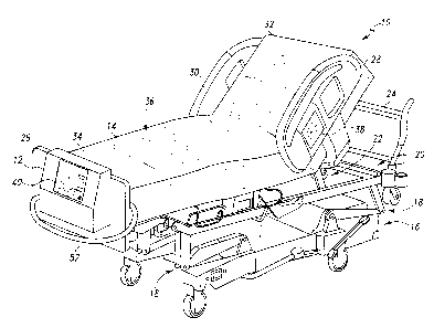
Fig. 1 illustrates a hospital bed 10 having a therapeutic support surface, for
example a mattress 14 having air bladders 48, 50 (Fig. 6), and a touch screen
control system 12
for controlling lateral rotation of the mattress 14. The hospital bed 10
includes a base frame 16,
an intermediate frame 20 coupled to the base frame 16 by linkages 18, and an
articulating deck
frame 22 that is coupled to the intermediate frame 20 and that supports the
mattress 14. The bed
10 also includes a head end 24, a foot end 26, a left side rail 28, and a
right side rail 30. The
deck frame 22 includes separate sections that articulate relative to the base
frame 16 and relative
to each other, for example, a mattress center section 36 that is height
adjustable, and a mattress
head section 32 and a mattress foot section 34 that are adjustable in
elevation relative to the
mattress center section 36. A patient control panel 38 is used to control
articulation of the deck
frame 22.
The present disclosure is directed to a system and method for setting and
monitoring lateral rotational therapy of mattress 14. The air bladders 48, 50
of the mattress 14
are used to provide positioning and/or therapy, for example, rotational
therapy, percussion
therapy, vibration therapy, and positioning to assist turning of the patient.
Referring to Fig. 6, the
touch screen control system 12 includes a touch screen 40, an electrical
control system 42, and a
CA 02529185 2005-12-06
-5-
pneumatic control system 46. The electrical control system 42 includes a
controller 44 and is
electrically coupled to the touch screen 40 and the pneumatic control system
46.
The electrical control system 42 provides control and monitoring of the
pneumatic
control system 46. The touch screen 40 provides a graphical user interface for
setting and
monitoring the electrical control system 42 and the pneumatic control system
46, which in turn
actuate pneumatic aspects of the mattress 14. The pneumatic control system 46
operates a
bladder system 47 associated with the mattress 14. The bladder system 47 may
include, for
example a right rotation bladder 48 and a left rotation bladder 50, or an
alternative arrangement
of one or more bladders to provide desired patient position and therapy. The
pneumatic control
system 46 is coupled to the right rotation bladder 48 and the left rotation
bladder 50 by
pneumatic lines 52. Additionally, pressure sensors (not shown) or alternative
type sensors such
as capacitive, inductive, or optical sensors, may also provide feedback
control of the bladders 48
and 50 to the pneumatic control system 46 or the electrical control system 42.
The pneumatic control system 46 generally provides pressure or vacuum to, or
sealing of the pneumatic lines 52 in order to selectively inflate, deflate, or
maintain the inflation
of the bladders 48 and 50. For example, to rotate a patient on the mattress 14
toward the right,
the pneumatic control system 46 deflates the right rotation bladder 48 located
under the patient's
right side and inflates the left rotation bladder 50 located under the
patient's left side.
Alternatively, only one of or a portion of the bladders of the bladder system
47 may be actuated
by inflation or deflation to laterally rotate a patient on mattress 14 to
different rotational
positions. Additionally, the bladder system 47 may comprise bladders that are
associated with
the mattress 14 in an arrangement different from that shown in Fig. 6, as is
known in the art. For
example, the bladder system 47 may include vertically stacked bladders, one of
which is
normally inflated and another that is inflated or deflated to provide
rotation. Additionally, the
pneumatic control system 46 may also provide other pneumatic control, for
example, to provide
percussion, vibration, or other desired patient therapy or positioning. The
pneumatic control
system 46 and the bladder system 47 of mattress 14 may alternatively include a
non-pneumatic
mechanical or electrometrical control and motion system, or a pneumatic system
utilizing
movement elements other than bladders.
Referring to Fig. 2, the touch screen 40 is shown having an exemplary display
arrangement; however, alternative display and control arrangements may be
utilized. The
CA 02529185 2005-12-06
-6-
exemplary display arrangement of the touch screen 40 includes a menu display
area 60, a status
display area 62, and other graphical user interface elements, for example, a
start button 64, a stop
button 66, and an alarm silence button 68. The touch screen 40 is of the type
that provides visual
display elements as well as a touch sensitive surface so that particular
display elements may be
selected or otherwise manipulated by touching the display surface with a
finger or other object
and/or dragging the finger or other object across the surface. The electrical
control system 42
provides signals to touch screen 40 for displaying the various display
elements, and receives
signals from the touch screen 40 relating to touch selected functions.
The menu display area 60 may include menu tabs 70 for selecting between
various menu display pages, for example, home, rotation, percussion,
vibration, maximum
inflate, turn assist, and opti-rest. Each menu page such as the home page that
is shown in the
menu display area 60 may include informational display elements as well as
display elements
that may be selected or otherwise manipulated by touch in order to set or
monitor aspects of the
various functions associated with the menu display pages.
The exemplary status display area 62 shown in Fig. 2 relates to rotational
therapy
and is used for monitoring and controlling the pneumatic control system 46 and
the bladder
system 47. Specifically, the exemplary status area 62 relates to lateral
rotation, percussion, and
vibration of mattress 14 and the bladder system 47 for pulmonary therapy or
decubitus
preventional treatment. The exemplary status area 62 is sub-divided into a
rotation display area
72, percussion display area 74, and vibration display area 76. The exemplary
display areas 72,
74 and 76 include graphical elements for setting and/or monitoring the
rotational position and the
dwell time for a right rotational position, central rotational position, and
left rotational position,
and the frequency, intensity, and duration of percussion and vibration therapy
in each of the three
positions. A graphical element is defined as including at least one of a
graphic, letter, and
number elements.
The right rotational position is defined as a lateral rotational position in
which the
patient is rotated toward the right hand side of the patient. The left
rotational position is defined
as a lateral rotational position in which the patient is rotated toward the
left hand side of the
patient. The central rotational position is defined as a lateral rotational
position in which the
patient is positioned between the right and left rotational positions. The
central rotational
position may or may not be the position in which the patient is laterally
parallel with the base
CA 02529185 2005-12-06
frame 16 of hospital bed 10. The rotational position may be set and displayed
as, for example, a
percentage of the full range of lateral rotation or the lateral rotational
angle relative to the patient
(or mattress 14) being laterally parallel to the base frame 16. A rotational
dwell time is also
associated with each of the rotational positions. The dwell time is the length
of time the
electrical control system 42 signals the pneumatic control system 46 to
maintain the bladder
system 47 in one of the patient rotational positions before signaling the
pneumatic control system
46 to actuate the bladder system 47 to provide another of the patient
rotational positions. The
rotational dwell time may be set and displayed, for example, in units of time
such as seconds or
minutes.
The exemplary rotational display area 72 includes a patient display element
78,
numerical indication 80, and dwell time display elements 82, 84, and 86 for
the right, central and
left rotational positions respectively. The patient display element 78 may be,
for example, a
graphical representation of a patient viewed axially from the foot end 26 of
the hospital bed 10
because the touch screen control system 12 may be located at the foot end 26.
The patient
display element 78 may also include labeling of the patients right side and
left side to indicate
the direction of rotation of the patient for the various rotational positions.
The patient display element 78 provides visual indication of the amount of
selected rotation and the direction of rotation. This aspect of control system
12 is helpful
visually confirming the actual rotational displacement that will result from a
specific numerical
setting. For example, various bed systems use degrees, percent of maximum
rotation, or a
different basis for setting the rotational displacement. Thus, a numerical
setting of for example,
45 may anticipate a rotation of 45 degrees, but may actually be setting 45
percent of the
maximum rotation, for example, 18 degrees for a bed with a maximum rotation of
40 degrees.
The patient display element 78 also provides a visual indication of the
direction of rotation. For
example, the exemplary patient display element 78 shown in Fig. 2 graphically
represents a
patient viewed from the approximate vantage point of a person using the
control system 12.
Thus the rotation of the patient display element 78 approximately matches the
real-world view of
the patient direction of rotation and the amount of rotation.
Fig. 3 illustrates using the rotation display area 72 of the exemplary display
arrangement of the touch screen 40 to set the rotational position of the right
rotational position of
the patient on the mattress 14. In order to select which of the rotational
positions, right, central,
CA 02529185 2005-12-06
_g_
or left is to be set, one of the position labels 88 located above the
numerical indication 80 is
pressed. To set the rotational position, the patient display element 78 is
touched with a finger 79
and the finger is moved across the surface of the touch screen 40. The
electrical control system
42 and touch screen 40 are programmed to rotate the patient display element 78
accordingly to
the touch and movement of touch on the patient display element 78 portion of
the touch screen
40.
For example, Fig. 3 illustrates touching with the finger 79 the side of the
patient
display element 78 labeled as the right hand patient side and dragging the
finger 79 downward.
Electrical control system 42 rotates the patient display element 78 toward the
right hand patient
side in response to the dragging of the finger. Simultaneously, the electrical
control system 42
displays the numerical indication 80 (Fig. 4) of the right rotational position
setting, which is also
proportional to the rotation of patient display element 78.
The central rotational positions and left rotational position can similarly be
set by
touching the appropriate position label 88 and touching and dragging the
patient display element
78 to provide the desired amount of rotation as indicated by the numerical
indication 80.
Referring to Fig. 4, a dwell time 83, 85, and 87 may also be associated with
and
selected for each of the rotational positions. Fig. 4 illustrates touching the
right dwell time
display element 82 with a finger 79 to set the desired dwell time 83. The
exemplary dwell time
display element 82, 84, and 86 include a circular dial having an arrow
pointing to the desired
setting 83, 85, and 87 and labeled along the circumference of the dial in
seconds and minutes.
For example, Fig. 4 illustrates touching the arrow portion of the right dwell
time display element
82 and dragging the finger 79 across the surface of the touch screen 40 to set
the right dwell time
83 to 20 minutes. The dwell time 85 and 87 for the central and left positions
can be similarly set
using the central dwell time display element 84 and the left dwell time
display element 86.
Alternative graphical elements and arrangements may also be utilized in place
of the exemplary
dwell time display elements 82, 84, and 86.
Fig. 5 illustrates a portion of an exemplary alternative rotational display
area 90
that may be substituted for the display area 72. The alternative display area
90 includes a central
patient display element 92 for setting and displaying the central rotational
position, a right
display element 94 for setting and displaying the right rotational position, a
left display element
96 for setting and displaying the left rotational patient position, and
selectable graphical buttons
CA 02529185 2005-12-06
-9-
98 and 100 for selecting between symmetric and asymmetric rotation.
Alternatively, the display
element 92 may represent the current rotational position of the patient on the
mattress 14, and the
right display element 94 and the left display element 96 may represent the
rotational position
settings for right and left patient rotation respectfully.
Fig. 7 is a flow-chart illustrating the software algorithm 200 associated with
the
controller 44 of the electrical control system 42 for enabling the above-
described aspects of the
touch screen control system 12 illustrated in Figs. 2-4. The algorithm 200
begins at step 202. In
step 204, the controller 44 commands display of the graphical elements
associated with rotational
settings on the touch screen 40, for example the patient display element 78,
the numerical
rotational indicators 80, and the dwell time display elements 82, 84, and 86.
In step 206, the
controller 44 determines whether one of the display elements 78, 80, 82, 84,
and 86 is being
touched. If the controller 44 determines a display element is being touched,
the algorithm 200
continues at step 208, else the algorithm 200 continues at step 212.
In step 208, the controller 44 adjusts the display element being touched in
response to the touching of the touch screen 40. For example, if the
controller 44 determines the
patient display element 78 is being touched, the element 78 is rotated in
accordance with touch
of and the movement of touch across the touch screen 40. In addition, the
controller 44 changes
the numerical indication 80 according to the movement of the patient display
element 78.
Similarly, if the controller 44 determines one of the dwell time display
elements 82, 84, or 86 is
being touched, the appropriate display element will be changed and displayed
according to the
touch of touch screen 40.
In step 210, the controller 44 stores the rotational parameter associated with
the
display element being touched. More specifically, the left, central, or right
rotational position is
set and stored, for example in memory (not shown) associated with the
electrical control system
42, based on the touching of the patient display element 78 detected by the
controller 44, and the
right, central, and left rotational dwell time 83, 85, and 87 is set and
stored if the controller 44
determines that the dwell time display element 82, 84 or 86 is being touched.
In step 212, the controller 44 determines whether rotational therapy is
selected,
for example by determining that the start button 64 has been touched on the
menu display area
60 of the touch screen 40. If the controller 44 determines that rotational
therapy is selected, the
algorithm 200 continues at step 214, else the algorithm 200 returns to step
204. In step 214, the
CA 02529185 2005-12-06
-10-
controller 44 enables the electrical control system 42 to control the
pneumatic control system 46.
For example, the pneumatic control system 46 is commanded to inflate or
deflate the right
rotational bladder 48 and the left rotational bladder 50 of the bladder system
47 in order to
provide the rotation, percussion, and vibration of the mattress 14 according
to the selected made
and the stored rotational and other parameters. For example, if rotational
therapy is selected, the
controller 44 signals the pneumatic control system 46 to sequence the bladder
system 47 through
the right, central, and left rotational positions, maintaining each position
for the respective dwell
time 83, 85 and 87. In step 216, the algorithm 200 is complete. In addition to
the algorithm 200,
the controller 44 may include other software to enable other aspects of the
exemplary display
arrangement shown in Fig. 2 and the other functionality of the electrical
control system 42 and
the pneumatic control system 46 according to the present invention.
Although certain illustrative embodiments have been described in detail above,
variations and modifications exist within the scope and spirit of this
disclosure as described and
as defined in the following claims.