Note: Descriptions are shown in the official language in which they were submitted.
CA 02529259 2005-12-06
PIPE JOINT STRUCTURES AND METHODS OF MANUFACTURING SUCH
STRUCTURES
BACKGROUND OF THE INVENTION
1. Field of the Invention
[0001] The present invention relates to pipe joint structures and methods of
manufacturing
such structures, and more specifically, to pipe joint structures suitable for
forming connections
between an heat exchange medium introduction pipe or an heat exchange medium
discharge pipe,
or both, and a heat exchanger core used in a vehicle, and methods for
manufacturing such
structures.
2. Description of Related Art
[0002] A known, pipe joint structure used for forming connections between an
heat exchange
medium introduction or an heat exchange medium discharge pipe, or both, and a
heat exchanger
core is depicted in Fig. 12. Such structures are described in Japanese Patent
Application No. JP-
A-2004-36944. In Fig. 12, a pipe joint 100 has a flange 101 and pipes 102 and
103. Through
holes 104 and IOS, into which pipes 102 and 103 are inserted, are formed
through in flange 101.
Flange recessed portions 106 and 107 are formed at circumferential portions of
through holes
104 and 105 at positions on the pipe insertion side of flange 101. Flange
recessed portions 106
and 107 are formed with a polygonal shape, as depicted in Fig. 13, or a
serrated shape. On the
other hand, collars 108 and 109, each projecting in a radial direction of its
pipe, are provided at
the ends of pipes 102 and 103.
[0003] In such a pipe joint structure, an outer diameter b of collar 108 of
pipe 102 is slightly
greater than an inner diameter a of flange recessed portion 106, and an outer
diameter d of collar
109 of pipe 103 is slightly greater than an inner diameter c of flange
recessed portion 107. Pipes
102 and 103 are connected to flange 101 by press-fitting collars 108 and 109
into flange recessed
portions 106 and 107, respectively.
[0004] In the above-described press-fitting method of collar portions of pipes
are fitted into
flange recessed portions, however, deformation or breakage may occur in the
collars, and the
connection strength may be reduced. Further, when a collar is formed with an
annular shape and
a flange recessed portion is formed with a polygonal shape, as depicted in
Fig. 13, gaps 110 are
formed between the collar and the inner surface of the flange recessed
portion, and the
connection area therebetween decreases, and the connection strength may be
reduced. Further,
when a flange recessed portion is formed with a polygonal shape or a serrated
shape, because it
CA 02529259 2005-12-06
is difficult or impossible to shape it by cutting, forging or casting is
required, and this may
increase of the cost for manufacturing the flange. Moreover, there is a risk
that condensation
may collect in gaps I 10, and a so-called refrigeration puncture may occur.
SUMMARY OF THE INVENTION
[0005] Accordingly, a need has arisen for pipe joint structures and methods of
manufacturing
such structures, which may connect a pipe and a flange securely and with
certainty and which
may reduce the cost of manufacture.
[0006] To achieve the foregoing and other objects, a pipe joint structure
according to the
present invention comprises at least one pipe with a collar projecting
radially from the at least
one pipe, and a flange having a pipe insertion hole formed through an end of
the pipe and a
flange recessed portion provided at a circumferential portion of the pipe
insertion hole and
adapted to receive the collar, wherein an inner diameter of the flange
recessed portion is greater
than an outer diameter of the collar, and the collar of the pipe is
plastically deformable in a radial
direction to bring the collar into surface contact with an inner surface of
the flange recessed
portion.
[0007] In this pipe joint structure, because the inner diameter of the flange
recessed portion is
greater than the outer diameter of the collar of the pipe, the collar may be
inserted into the flange
recessed portion with a predetermined amount of play (~, range or freedom of
motion). In this
condition, the collar of the pipe is plastically deformable in its radial
direction, and the deformed
collar may be brought into contact with the inner surface of the flange
recessed portion.
Therefore, while preventing an undesirable deformation or breakage of a collar
as in a known,
pipe joint structure in which the collar is press-fitted into a flange
recessed portion, the pipe may
be connected to the flange readily and securely. Further, no gap is formed
between the collar
and the flange recessed portion as in the known structure shown in Fig. 13,
and the risk of a
refrigeration puncture may be reduced, minimized, or eliminated.
[0008] In pipe joint structures according to the present invention, it is
preferred that the collar
is formed with an annular shape. Further, the collar may be formed as a
protruded portion which
is formed by protruding a portion of the pipe in its radial direction.
[0009] Further, it is preferred that a thickness of the collar in an axial
direction of the pipe
before the above-described plastic deformation is greater than a depth of the
flange recessed
portion. In such structures, when the collar is plastically deformed, the
surface of the collar and
the surface of the flange at the pipe insertion side may become flush with
each other.
-2-
CA 02529259 2005-12-06
[0010] Further, it is preferred that the flange recessed portion has a
circular arc extending
more than a semicircle. When the Mange recessed portion is of a circular arc
extending more
than a semicircle, and, further, the collar has an annular shape, because the
collar and the inner
surface of the flange recessed portion may be brought into surface contact
with each other
without the presence of a gap, a high strength connection therebetween may be
achieved.
Further, because arc-type flange recessed portion may be formed readily by
machining, such as
by cutting; such a structure may contribute to a reduction of the cost for
manufacture.
[0011] In the present invention, a plurality of pipe insertion holes may be
formed through the
flange, a plurality of flange recessed portions may be formed in the flange,
and a plurality of
pipes are inserted into the pipe insertion holes, respectively. For example,
one pipe may be
provided as a heat exchange medium introduction pipe into a heat exchanger,
and another pipe
may be provided as a heat exchange medium discharge pipe from the heat
exchanger.
[0012] Further, it is preferred that the flange recessed portion has a tapered
shape, the
diameter of which gradually decreases toward a pipe insertion side. In such a
structure, the pipe
and the flange may be connected more securely, and dislodging the plastically
deformed collar
from the flange recessed portion and the like may be prevented with more
certainly.
[0013] In a method for manufacturing a pipe joint structure according to the
present invention,
an end of a pipe with a collar projecting radially may be inserted into a pipe
insertion hole of a
flange, and the collar of the pipe is adapted to be received into a flange
recessed portion provided
at a circumferential portion of the pipe insertion hole. This method comprises
the steps of
inserting the collar of the pipe into the flange recessed portion, and
deforming the inserted collar
plastically in a radial direction to bring the collar into surface contact
with an inner surface of the
flange recessed portion.
[0014] In such a method, the inner diameter of the flange recessed portion may
be greater
than the outer diameter of the collar of the pipe, and the collar may be
inserted into the flange
recessed portion at a condition with a predetermined amount of play. In this
condition, the collar
of the pipe may be plastically deformed in its radial direction, and the
deformed collar may be
brought into contact with the inner surface of the flange recessed portion.
Therefore, while
preventing an undesirable deformation or breakage of a collar as in known,
pipe joint structures
in which the collar is press-fitted into a flange recessed portion, the pipe
may be connected to the
flange readily and securely. Further, because a gap is not formed between the
collar and the
-3-
CA 02529259 2005-12-06
flange recessed portion as in a known structure depicted in Fig. 13, a risk of
a refrigeration
puncture may be reduced, minimized, or eliminated.
[0015] Thus, in pipe joint structures and methods of manufacturing such
structure according
to the present invention, an undesirable deformation or breakage of a collar
of a pipe may be
reduced, minimized, or eliminated, and the pipe may be connected to the flange
readily and
securely.
[0016] Other objects, features, and advantages of the present invention will
be apparent to
persons of ordinary skill in the art from the following detailed description
of preferred
embodiments of the present invention and the accompanying drawings.
BRIEF DESCRIPTION OF THE DRAWINGS
[0017] For a more complete understanding of the present invention, the needs
satisfied
thereby, and the objects, features, and advantages thereof, reference now is
made to the
following description taken in connection with the accompanying drawings.
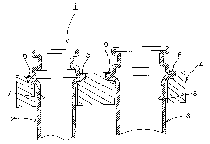
[0018] Fig. 1 is a cross-sectional view of a pipe joint structure according to
an embodiment of
the present invention.
[0019] Fig. 2 is a plan view of a flange in the pipe joint structure depicted
in Fig. 1.
[0020] Fig. 3 is a cross-sectional view of the flange depicted in Fig. 2, as
viewed along III-III
line of Fig. 2.
[0021 ] Fig. 4 is an enlarged, cross-sectional view of the structure depicted
in Fig. 1, showing
an insertion state of a pipe into a flange recessed portion before deforming a
collar plastically.
[0022] Figs. 5A and SB are cross-sectional views of the structure depicted in
Fig. 1, showing
a method of manufacturing the structure.
[0023] Fig. 6 is a partial cross-sectional view of the structure depicted in
Fig. 1, showing a
contact condition between a collar and a flange recessed portion when the
collar is plastically
deformed.
[0024] Fig. 7 is a plan view of a flange according to another embodiment of
the claimed
invention.
[0025] Fig. 8 is a plan view of a flange according to a further embodiment of
the claimed
invention.
[0026] Fig. 9 is a plan view of a flange according to still a further
embodiment of the claimed
invention.
-4-
CA 02529259 2005-12-06
[0027] Figs. 10A and lOB are cross-sectional views of a pipe joint structure
according to get
another embodiment of the present invention, showing a process for
manufacturing the structure.
[0028] Fig. 11 is an enlarged, partial, cross-sectional view of a flange in
the structure
according to the embodiment depicted in Figs. 10A and 10B.
[0029] Fig. 12 is an exploded, cross-sectional view of a known, pipe joint
structure.
[0030] Fig. 13 is a cross-sectional view of a known, pipe joint structure,
showing a contact
condition between a collar and a flange recessed portion.
DETAILED DESCRIPTION OF PREFERRED EMBODIMENTS
[0031] Fig. 1 depicts a pipe joint structure 1 according to an embodiment of
the present
invention. In Fig. 1, pipe joint structure 1 comprises pipes 2 and 3 and a
flange 4. In this
embodiment, pipe 2 is provided as an heat exchange medium introduction pipe
into a heat
exchanger, and pipe 3 is provided as an heat exchange medium discharge pipe
from the heat
exchanger. Annular collars 5 and 6 are disposed on pipes 2 and 3,
respectively. In this
embodiment, collars 5 and 6 are formed as protruded portions of pipes 2 and 3,
each formed by
protruding a portion of pipe 2 or 3 in its radially outer direction. These
protruded portions may
be formed readily by pressing and the like.
[0032] As depicted in Figs. 2 and 3, pipe insertion holes 7 and 8 are formed
through flange 4
for receiving the ends of pipes 2 and 3. Circular flange recessed portions 9
and 10 are formed
around pipe insertion holes 7 and 8 on a surface 16 of flange 4, formed at the
pipe insertion side
for receiving collars 5 and 6. Inner diameters p and q of flange recessed
portions 9 and 10,
respectively, are greater than outer diameters r and s of collars 5 and 6,
respectively.
[0033] As depicted in Fig. 4, depth m of flange recessed portion 9 and 10 is
less than
thickness n of collars 5 and 6 in the axial direction of pipe 2 or 3 before
collars 5 and 6 are
deformed. The relationship between the above-described m and n is preferably
n?m, and more
preferably, the ratio between m and n is within a range of 0.5 c m/n ~ 1.
[0034] A method of manufacturing pipe joint structure 1 of the above-described
embodiment
now is explained.
[0035] First, the end portions of pipes 2 and 3 are inserted into pipe
insertion holes 7 and 8 of
flange 4, and collars 5 and 6 of pipes 2 and 3 are fitted into corresponding
flange recessed
portions 9 and 10. Because inner diameters p and q of flange recessed portions
9 and 10 are
greater than outer diameters r and s of collars 5 and 6 (i.e., p>r and q>s),
collars 5 and 6 are
inserted into flange recessed portions 9 and 10 with predetermined amounts of
play, as depicted
-5-
CA 02529259 2005-12-06
in Fig. 4. Then, as depicted in Fig. 5A, collars 5 and 6 may be pressed, for
example, by a punch
I I, from upper side, and collars 5 and 6 may be deformed plastically in their
radial directions,
respectively. Because punch 11 may comprise holes 12 and 13 formed therein,
connection
portions 14 and 15 (~, connection portions to be connected to an expansion
valve) of
respective pipes 2 and 3 are not deformed, and only collars 5 and 6 are
plastically deformed in
their radial directions by the outer circumferential portions of the holes 12
and 13. In this
embodiment, as depicted in Fig. 5B, collars 5 and 6 are plastically deformed
to be flush with
surface 16 of flange 4 on at the pipe insertion side.
[0036] Collars 5 and 6 are deformed plastically to be brought into contact
with inner surfaces
17 and 18 of flange recessed portions 9 and 10 without generating a gap over
the entire
circumference. Although each of flange recessed portions 9 and 10 may be
formed with a
circular shape, and the entire circumference of each of collars 5 and 6 is
brought into surface
contact with each of inner surfaces 17 and 18 in this embodiment, if greater
than half i.e., >
50%) of the circumference of annular collar 5 or 6 is brought into surface
contact with inner
surfaces 17 or 18, a connection of sufficient strength between a pipe and a
flange may be
achieved. Therefore, flange recessed portions 9 and 10 may be formed with a
circular arc,
extending more than a semicircle, as depicted in Figs. 7 to 9, respectively.
Further, because
these circular or circular arc, flange recessed portions may be processed
readily by machining,
such as cutting, the cost for manufacturing a flange may be significantly
reduced as compared
with a known manufacturing methods in which forging or casting has been
required.
[0037] Further, in this embodiment, because inner diameters p and q of flange
recessed
portions 9 and 10 are greater than outer diameters r and s of collars 5 and 6,
respectively, collars
and 6 are inserted into flange recessed portions 9 and 10 with predetermined
amounts of play.
When collars 5 and 6 are plastically deformed in the radial directions of
pipes 2 and 3, plastically
deformed collars 5 and 6 are brought into surface contact with inner surfaces
17 and 18 of flange
recessed portions 9 and 10, respectively. Therefore, while preventing an
undesirable
deformation or breakage of collars as in a known structures in which collars
are press-fitted into
flange recessed portions, pipes 2 and 3 may be connected to flange 4 readily
and securely.
Further, because there may be no gap between collars 5 and 6 and flange
recessed portions 9 and
10, a refrigeration puncture may be prevented.
[0038] Figs. 10A and lOB depict a pipe joint structure and a method of
manufacturing such
structures, according to another embodiment of the present invention. Each of
flange recessed
-6-
CA 02529259 2005-12-06
portions 20 and 21 of flange 19 are formed with a tapered shape, the diameter
of which gradually
decreases toward a surface 22 of flange 19 on the pipe insertion side, as
depicted in Fig. 11. In
addition, in this embodiment, as depicted in Fig. 10A, collars 5 and 6 may be
pressed, for
example, by a punch 23, from upper side, and, as depicted in Fig. IOB, collars
5 and 6 may be
plastically deformed into flange recessed portions 20 and 21, and collars 5
and 6 and flange 19
may be connected securely to each other. In this embodiment, because each of
flange recessed
portions 20 and 21 is formed with a tapered shape, the diameter of which
gradually decreases
toward surface 22 on the pipe insertion side, dislodging collars 5 and 6 from
flange recessed
portions 20 may be prevented with more certainty. Therefore, the connection
between the pipes
and the flange may be strengthened.
(0039] The pipe joint structures and the methods of manufacturing such
structures, according
to the present invention, may be broadly applied to many joint structures
comprising a pipe and a
flange, and in particular, they are suitable for connections between an heat
exchange medium
introduction pipes or on heat exchange medium discharge pipe, or both, and
heat exchanger core
used in a vehicle.
[0040] While the invention has been described in connection with preferred
embodiments, it
will be understood by those skilled in the art that variations and
modifications of the preferred
embodiments described above may be made without departing from the scope of
the invention.
Other embodiments will be apparent to those skilled in the art from a
consideration of the
specification or from a practice of the invention disclosed herein. It is
intended that the
specification and the described examples are considered exemplary only, with
the true scope of
the invention indicated by the following claims.