Note: Descriptions are shown in the official language in which they were submitted.
CA 02529372 2009-03-02
AFFIXING AN ANCHOR IN A DRILLED HOLE
This invention relates to a method of and apparatus for affixing an
anchor in a drilled hole.
It is well known that such drilled holes can be formed in concrete or
other materials but the field with which the present invention is concerned is
primarily concrete anchors.
The use of a setting or curing resin or other plastic material to bond an
anchor into a drilled hole is known from a number of prior art documents. In
particular US patent 6,484,471 of the present inventors issued November 26,
2002
discloses a method in which an anchor is inserted into a drilled hole with the
anchor
having a central core within which is a chemical which reacts with oxygen in
an
exothermic reaction to generate heat within the anchor to affect an adhesive
material
on the exterior of the anchor.
It is known that the anchor itself may be formed of a threaded rod or
may be more complex in shape including a threaded section and a bottom insert
section. In most cases however the bottom insert section will have external
projections for engaging into the adhesive or resin material on the exterior
surface.
Thus the arrangement disclosed herein can utilize any of the above features
including those disclosed in the above patent.
US Patent 6,484,471 describes the method of placing the adhesive on
the anchor, thus eliminating the problems involved with mixing adhesives,
usually
consisting of two or more compounds, and after mixing, applying these
adhesives
into holes provided for the anchors. The arrangement shown herein, while
useful
CA 02529372 2009-03-02
2
under certain conditions, is expensive to manufacture and difficult to store
and
handle.
An induction heating head or probe is disclosed for example in US
patent 4,355,222 (Geithman) assigned to Boeing and issued October 19tn 1982.
This patent discloses a technique by which a cylindrical ferrite core is
excited with 35
kHz energy for a period of about 10 seconds thereby heating the fastener to
approximately 600 degrees F.
SUMMARY OF THE INVENTION
It is one object of the present invention to provide an improved method
and apparatus for affixing an adhesive anchor in a hole for adhesive
attachment of
the anchor in the hole.
According to one aspect of the invention there is provided method for
affixing an anchor to a substrate rock or concrete layer comprising:
drilling a hole in the substrate layer such that at least a part of the hole
extending from a bottom end of the hole has a hole wall of constant diameter
along
its length;
providing an anchor in the form of a solid metal rod having a cylindrical
first end portion shaped and arranged to fit in the hole wall and a second end
portion
integral with the first portion arranged to project outwardly from the hole
beyond the
substrate layer;
supplying the anchor with a surrounding layer on said first end portion
of a hot melt adhesive of a character that it softens when heated and sets
when it
cools;
CA 02529372 2009-03-02
3
said surrounding layer forming a cylindrical sleeve surrounding said
first end portion;
said first end portion including projecting elements thereon extending
outwardly therefrom and engaging into the surrounding adhesive layer;
inserting said one first end portion with the adhesive layer thereon as
supplied into the hole to a required depth of insertion of the first end
portion in the
hole, at which depth the cylindrical sleeve of said surrounding adhesive has
an outer
cylindrical surface immediately adjacent the hole wall and at which depth the
second
portion of the anchor rod is exposed outside the substrate layer out of the
hole;
and, while the second portion remains exposed outside the substrate
layer out of the hole, attaching the anchor rod into the hole by causing
heating of the
surrounding adhesive layer in the hole between the hole wall and the first end
portion so as to soften the surrounding adhesive layer and by allowing the
adhesive
layer to cool so as to set in the hole so that the cylindrical outer surface
of the
surrounding adhesive layer is adhesively attached to the hole wall.
Preferably the projections on said first end portion are formed by a
male thread thereon.
Preferably the projections extend to a position closely adjacent the
hole wall so that there are substantially no shear forces in the surrounding
adhesive
layer after the adhesive layer is set.
Preferably the rod remains at the required depth of insertion and does
not move longitudinally during heating and cooling of the adhesive.
CA 02529372 2009-03-02
4
Preferably the surrounding adhesive layer extends along the full length
of the first portion.
Preferably the adhesive is caused to be heated by applying inductive
heating by an inductive heating device in a heating cycle to the exposed
second
portion of the anchor.
According to a second aspect of the invention there is provided an
anchor for affixing in a hole drilled in a substrate of a rock or concrete
layer where
the hole is drilled in the substrate layer such that at least a part of the
hole extending
from a bottom end of the hole has a hole wall of constant diameter along its
length,
the anchor comprising:
a solid metal rod having a cylindrical first end portion shaped and
arranged to fit in the hole wall and a second end portion integral with the
first portion
arranged to project outwardly from the hole beyond the substrate layer;
a surrounding layer on said first end portion of a hot melt adhesive of a
character that it softens when heated and sets when it cools;
said surrounding layer defining a cylindrical sleeve of set hot melt
adhesive surrounding said first end portion;
said first end portion including projecting elements thereon extending
outwardly therefrom and engaging into the surrounding adhesive layer;
the cylindrical sleeve of said surrounding adhesive having an outer
cylindrical surface dimensioned transversely so as, when inserted to the hole
wall, to
lie immediately adjacent the hole wall such that in use the anchor rod is
attached
into the hole by causing heating of the surrounding adhesive layer in the hole
CA 02529372 2009-03-02
between the hole wall and the first end portion so as to soften the
surrounding
adhesive layer and by allowing the adhesive layer to cool so as to set in the
hole so
that the cylindrical outer surface of the surrounding adhesive layer is
adhesively
attached to the hole wall.
5 DESCRIPTION OF THE DRAWINGS
One embodiment of the invention will now be described in conjunction
with the accompanying drawings in which:
Figure 1 is a cross sectional view showing an anchor inserted into a
drilled hole prior to activation of the adhesive.
Figure 2 is a similar cross sectional view showing the anchor inserted
and in the process of being heated by an induction heating head.
Figure 3 is a cross sectional view showing the finished installed
anchor.
Figure 4 is an isometric view of the anchor and induction heating
assembly with the housing omitted for convenience of illustration.
Figure 5 is schematic illustration of induction heating assembly of
Figure 4.
In the drawings like characters of reference indicate corresponding
parts in the different figures.
DETAILED DESCRIPTION
In Figure 1 is shown an anchor body 10 in the form of a rod with
external projections 11 in an upper portion 12 and projections 13 in a lower
insert
CA 02529372 2009-03-02
6
portion 14 arranged to be inserted into a drilled hole 15 in a body of
concrete 16 or
the material.
The projections 11 and 13 are formed in the embodiment shown as a
continuous threaded section on the exterior of a rod. However other
projections can
be provided in many different arrangements as is well known to one skilled in
the art.
The anchor 10 carries on its exterior surface a band 18 of an adhesive
which has the character that it softens when heated and sets when it cools,
such as
a hot melt adhesive. Thus the band 18 is generally cylindrical where an inner
surface 19 in contact with and engagement with the exterior surface of the rod
so
that it follows the shape of the surface with the projections 13. The band 18
has an
exterior surface 20 which is generally cylindrical so as to approximately
match the
cylindrical surface of the drilled hole 15. The adhesive is thus formed with a
thickness which is the difference between the exterior diameter of the anchor
10 and
the interior diameter of the hole 15. This thickness is sufficient to allow
the
projections 13 to be received within the hole leaving a clearance between the
exterior of the projection and the interior of the hole. The difference in
diameter is
maintained relatively small so as to avoid providing shear forces through the
structure of the hot melt adhesive when force is applied to the anchor.
Hot melt adhesive is readily available from many manufacturers and
has the property that it is solid and non-tacky at ambient temperatures but
can be
melted at elevated temperatures well above ambient temperatures so that it
flows
and thus can enter pores and intestacies to provide an effect bond as the
material
cools and resets. Many different such thermoplastic materials are readily
available
CA 02529372 2009-03-02
7
providing a required strength and temperature of melting as will be determined
by a
person skilled in the art.
The anchor as supplied is inserted into the drilled hole 15 and an
induction heating head is applied over the upper section 11 of the anchor
which is
exposed above the hole. This arrangement can be used to heat the exterior
portion
11 above the hole so that the heat is conducted through the body of the anchor
to
the hot melt adhesive 18 to effect melting of the adhesive and spreading of
the
adhesive into the interior between the anchor and the drilled hole so as to
provide
bonding of the exterior surface of the adhesive into the interstices and pores
of the
drilled hole to adhesively attach the anchor into the drilled hole.
After activation of the adhesive 18, the anchor is completed by a
bracket 9 which is held in place by a washer 8 clamped by a nut 7 on the
threaded
portion 11.
One example is now described of a device and method which may be
used to produce a product at a considerably lower cost thereby making it
economically feasible for use by a larger number of individuals and companies.
By
retaining the concept of placing the adhesive on the anchor body as shown in
US
Patent 6,484,471 but replacing the internal heat source with an external
source a
much simpler and economical anchor can be produced.
The outside source of heat is generated by a known technology
generally referred to as induction heating. The process of induction heating
relies on
induced currents (eddy currents) within material to produce heat within that
material.
The basic components of an induction heating system are an alternating current
CA 02529372 2009-03-02
8
(AC) power supply, an induction coil and the article in which heat is to be
generated.
The power supply sends an alternating current through a coil, preferably
placed in
close proximity to the article to be heated. Under these circumstances, eddy
currents are induced within the article to be heated, generating controllable
amounts
of heat without physical contact between the coil and the article.
Alternating current at frequencies of 5 to 30 kHz are commonly used
and there is a direct relationship between the frequency of the alternating
current
and the depth of heat penetration and the time taken to heat an article of a
given
size. The induced current flow within an article is most intense on the
surface so the
outside of an object will heat more rapidly than the inner portion.
It is desirable to cause the metallic portion of the anchor to reach such
a temperature that the attached heat sensitive adhesive is brought to a
temperature
where, in the case of a two part adhesive coating, the activating agent and
the main
adhesive component are caused to melt or liquefy, later to cool and harden.
The method may use a single component adhesive is used, such as a
'hot melt' adhesive, where enough heat must be generated to bring the adhesive
to
a liquid or molten state. The use of induction heating provides the rapid
heating and
precise control of temperatures required to accomplish this.
There are three primary variables involved in attaining the required
amount of heat, the first being the size of the anchor installed. There is,
for the most
part, a direct relationship between the length and diameter of the various
anchors to
be used with this system.
CA 02529372 2009-03-02
9
Two other variables, ambient temperature and humidity within the
immediate area of the anchor to be activated are important in order to
determine the
precise amount of time the unit needs to operate to provide the required
temperature. Using known technology, two sensors are provided to make
measurable signals available to the microprocessor.
The control system of the heating device is arranged to control the
heating cycle in dependence upon these measured characteristics to ensure an
accurate application of heat to the exposed portion of the anchor and thus to
the
adhesive.
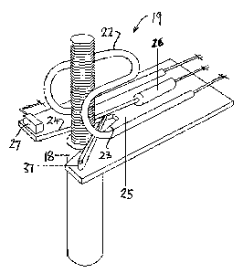
The heating device 19 includes a manually portable housing 20 which
can be lifted by the operator by a handle 20A and moved form anchor to anchor
located in a concrete substrate layer. The housing includes a circuit having a
manually operable switch 21 for actuation of heat to a coil 22.
The coil is located at a receptacle 23 in the form of a pair of surfaces
which define a V-shape by sides 24. This acts to locate the anchor when in the
V-
shaped receptacle so that it is properly placed within the heating coil above
the
receptacle 23.
At the receptacle is located a detecting or measuring arm 25 so that as
the anchor enters the receptacle it engages the arm 25 and depresses the arm.
The
arm is mounted on a sensor 26 so that it can move in dependence upon its
engagement with the anchor surface of the exposed portion of the anchor above
the
hole. The receptacle carries a micro-switch 27 which provides an indication of
when
the anchor is properly located in the receptacle.
CA 02529372 2009-03-02
The circuit receives power from a source 28 controlled by a power
supply module 29. The power to the coil is controlled in a heating cycle of
required
length for the conditions by a microprocessor controller 30. Input to the
microprocessor 30 is provided from the measuring arm sensor 26 and the gate
5 micro-switch 27 responsive to the presence of the anchor in the receptacle
and by
environment sensors including temperature sensor 31 and humidity sensor 32.
The sizing plate or receptacle 23, mentioned in the technical
description, with its V-shaped opening (sizing notch) defined by sides 24 and
the
position sensor (size (diameter) sensor) 33 provides a measurable signal,
related to
10 the diameter of the exposed portion of the anchor, to the microprocessor 30
in the
following manner. With the anchor positioned in its hole in the substrate and
before
the adhesive is activated, the unit carrying the sizing plate is positioned
before the
anchor and moved toward the anchor, the exposed portion of the anchor enters
the
V-shaped notch in the sizing plate. At some point, dependant on the diameter
of the
anchor, the sizing plate can not be moved further in a forward direction
because the
anchor has come to rest against both angle edges of the V-shaped notch. During
this operation, the sizing sensor arm 25 is forced rearward by contact with
the
exposed portion of the anchor and a measurable signal is made available to the
microprocessor indicating the diameter of the exposed portion of the anchor.
The sizing sensor 26 may be of known technology such as a
resistance measuring device which is calibrated in relation to the length and
angle of
the sizing slot edges so as to provide and accurate and repeatable signal
directly
related to anchor diameter.
CA 02529372 2009-03-02
11
When the operating switch 21 is activated information from these three
sensors 31, 32 and 33 is correlated within the programmable microprocessor
controller 30 to provide a time related signal to the power supply 29 which
then
operates for the required time period to supply induction heating energy to
the coil
22.
Due to the critical nature of the temperature levels required, it is
desirable to remove as much control as possible from the operator of the
device.
This is accomplished by providing the activating switch 21 of the momentary
contact
type which only begins the process, after which control is maintained by the
microprocessor. Two warning lights 35 and 36 are provided on the heating unit.
The first 35, green in color, is controlled by the microprocessor 30, and is
illuminated
when the unit is turned on or connected to line power, indicating to the
operator that
the unit is ready to use. A second warning light 36, red in color, also
controlled by
the microprocessor, illuminates when the momentary contact operating switch is
pressed and remains illuminated until the heating cycle is complete, after
which it is
turned off and the green warning light is illuminated informing the operator
that the
unit is ready to be applied to another anchor.
In order to prevent an anchor from being heated twice, an arm or gate
37 is positioned on the sizing plate or receptacle 23 in such a position that
it extends
across the opening leading to the V-shaped opening in the sizing plate 23. The
pivoted end of this gate 37 is spring loaded in order to return to its normal,
at rest,
position across the V-shaped opening. The opposite end of the spring loaded
arm
rests against the normally closed microswitch 27, which is also mounted on the
CA 02529372 2009-03-02
12
sizing plate, holding the switch 27 in its open position. When the unit is
positioned
before the anchor and moved in a forward direction, the movement of the
exposed
portion of the anchor into the V-shaped slot in the sizing plate 23 causes the
gate 37
to move away from the microswitch 27, allowing it to close. This information,
in the
form of a measurable signal informs the microprocessor that the unit is
positioned
over an anchor to be activated allowing the unit to operate through one cycle,
however, if the operating switch 21 is activated more than once without moving
the
unit away from the anchor to allow the gate to open the microswitch 27, the
microprocessor is programmed to block further operation.
When an inactivated anchor is to be processed the unit is positioned
before the anchor and then moved forward till the anchor enters the angled
sizing
notch in the receptacle or sizing plate. The unit is then moved forward until
the
anchor will not enter the notch further. At this time, the pivoted gate 37,
which
normally rests across the opening to the receptacle 23, is also displaced
rearwardly
by the movement of the exposed portion of the anchor. This causes the switch
27 to
move to its normally closed condition. Closing the switch 27 signals the
microprocessor to allow sensor readings from the ambient temperature sensor
31,
the humidity sensor 32 and the size sensor 33 to be correlated by the
microprocessor to calculate optimum time for operation of the heating coil. At
this
time, the green warning light is illuminated to inform the operator that the
unit is
ready to be activated.
When the operator presses the momentary contact operating switch 21
a signal is sent to the microprocessor 30. On receipt of this signal, the
CA 02529372 2009-03-02
13
microprocessor 30 turns off the green warning light and turns on the red
warning
light informing the operator that the heating process is under way. At the
same time,
the microprocessor sends a control signal to the power supply 29 which, in
turn,
supplies an alternating current of the preferred frequency to the heating coil
for the
precise amount of time required to heat the anchor and activate the adhesive.
At the
end of the heating cycle, the microprocessor 30 turns off the red warning
light. The
action of the green warning light is dependant upon the unit being removed
from the
activated anchor allowing the sizing plate gate switch to open.
Since various modifications can be made in my invention as herein
above described, and many apparently widely different embodiments of same made
within the spirit and scope of the claims without departing from such spirit
and
scope, it is intended that all matter contained in the accompanying
specification shall
be interpreted as illustrative only and not in a limiting sense.