Note: Descriptions are shown in the official language in which they were submitted.
CA 02530403 2005-12-21
WO 2005/004030 PCT/US2004/020070
METHOD FOR TEACHING MUSIC
BACKGROUND OF THE INVENTION
[0001] 1. Field of the Invention
[0002] The present invention relates to a method for teaching music to a
student or a group of students. More particularly, the present invention
relates to a
teaching method in which an instructor's manual operation of a musical
instrument
controls the illumination of guide lamps and a musical score display on each
student's
musical instrument. The instructor can visually indicate notes to the students
or even
guide the students through a musical performance.
[0003] 2. Description of the Related Art
[0004] Learning music can be demanding for a beginning student. He must
not only learn the language of music (treble clef, C note, etc.), but how the
language
relates to the instrument that he has chosen. For example, if the student has
chosen to
learn music on a keyboard instrument, he must learn the relationship between
the
notes to be played and the keys on the lceyboard. To achieve this level of
understanding can be very daunting and time-consuming. Furthermore, if the
student
wishes to apply his understanding to play a musical performance, he must at a
minimum learn which notes to play, when to play the notes and how long to hold
the
notes.
[0005] One conventional teaching method utilizes a musical instrument
having a performance guidance function to instruct the player. In this method,
the
student selects stored data of a musical performance to be played on the
instrument.
If the instrument is a lceyboard instrument, the performance guidance function
of the
instrument indicates which keys are to be operated, thereby guiding the
student
through the performance.
[0006] The keys to be operated can be indicated by a row of light emitting
diodes (LEDs) or guide lamps arranged adjacent to the keys of the lceyboard.
Each
guide lamp corresponds to a given lcey. As the musical performance to be
played
progresses, the guide lamps corresponding to the notes to be played are
sequentially
illuminated. The sequential illumination of the guide lamps informs the
student
which notes to play, when to play the notes and how long to hold the notes.
Some
CA 02530403 2005-12-21
WO 2005/004030 PCT/US2004/020070
instruments, such as disclosed in U.S. Patent No. 6,337,433, further indicate
which
finger of which hand should be used to operate a designated lcey.
[0007] The lceys to be operated can also be indicated tluough a liquid crystal
display (LCD) placed adjacent to the keys. The display can display a score of
the
musical performance or, alternatively, a drawing of the keyboard as disclosed
in U.S.
Patent No. 5,886,273. The drawing highlights the keys to be depressed during
the
musical performance. A scrolling function allows the student to know when to
depress and release the keys as the performance proceeds.
[0008] Although performance guidance functions such as guide lamps and a
score display can teach a student to play a musical performance, the teaching
method
is limited to individual instruction by following guide lamps which are
illmninated
under control of stored performance data. The student teaches himself or
herself to
play the musical performance by following the automated guide lamps or the
score
display. The teaching method does not involve teaching by a human instructor,
but
instead replaces the instructor.
[0009] A conventional method that allows for teaching a group of students is
disclosed at www.thevisualizer.com. The method involves the use of a large
display
device with a connection to a MIDI keyboard instrument. The display device
displays
a portion of a keyboard and a score and can be placed in front of a class of
students by
the teacher. When the teacher plays a note, the display device indicates the
played
note by highlighting in some manner the lcey corresponding to the note and
indicating
the note on the score display. The students must look at the display device
and then
look down at their respective lceyboards to depress the lcey indicated by the
display
device. Although such a display is useful to provide an indicator of keys to
be
depressed, it is difficult to look up at the display and then look down at the
lceyboard
to play a note, repeat the process for the next note and so on.
[0010] Thus, the conventional method utilizing instruments with a
performance guidance function is based on automated self instruction and
precludes
teaching by a human instructor, while the conventional method for group
teaching is
cumbersome.
BRIEF SUMMARY OF THE INVENTION
CA 02530403 2005-12-21
WO 2005/004030 PCT/US2004/020070
[0011] It is an object of the present invention to provide a method for
teaching
music by a human instructor to a student or a group of students by means of a
display
device associated with each student's instrument.
[0012] A first embodiment of the teaching method is directed to group
instruction of one or more students. In this embodiment, the instructor's
manual
operation of a musical instrument controls in real-time the illumination of
guide lamps
on each student's musical instrument. Specifically, as the instructor plays a
note,
MIDI data comprising light or lamp control data, as opposed to note playing
data, is
transmitted to the students' musical instruments. The lamp control data drives
the
guide lamps on each student's instrument to visually indicate the played note,
but
without generating a tone at the student's instrument. This allows the
students to
visually coimect the note to be played with the instructor's verbal
instruction and then
play the visually indicated note without having to look up at the instructor
or a distant
display.
[0013] An aspect of the first embodiment allows musical score information to
be displayed in real-time on each student's musical instrument. Specifically,
the
instructor's manual operation of his musical instrument not only controls in
real-time
the illumination of guide lamps corresponding to the played note, but also
provides a
score display of the played note on each student's musical instrument. The
students
can visually comlect the played note with the musical notation on the score
display.
Because the score display is on each student's musical instrument, the student
does
not have to divert attention from the instrument to look at a display device
in the front
of the classroom.
[0014] Yet another aspect of the first embodiment allows an instructor to lead
a student or a group of students based on performance data stored on an
external or
internal storage device associated with the instructor's musical instrument,
by using
the guide lamps of each student's musical instrument and by controlling the
progression of the stored performance data. A storage medium with stored MIDI
data
is inserted in the instructor's musical instrument. The stored MIDI data
drives guide
lamps corresponding to notes of the performance data to blink on the
instructor's
musical instrument as well as the students' musical instruments. The blincing
guide
lamp notifies each student of the notes to be played.
CA 02530403 2005-12-21
WO 2005/004030 PCT/US2004/020070
[0015] When the instructor plays the note indicated by the guide lamp on lus
musical instrument, the note is sounded by the instructor's instrument and the
guide
lamp corresponding to the note on each student's musical instrument is changed
from
the blinking light to a solid light. The students cause notes to be sounded at
their
keyboards by depressing a ltey in the normal fashion, so as to follow and join
the
performance of the instructor. If the stored MIDI data includes automatic
accompaniment data for the played note, accompaniment music is also played.
The
stored MIDI data then drives a guide lamp corresponding to the next note to
blinlt on
all of the musical instruments. In this mamer, stored MIDI data can be used to
illuminate the guide lamps of each student's musical instrument and possibly
provide
accompaniment, but the progression of the guide lamp illumination is
controlled by
the instructor in real-time. This allows the instructor to guide a student or
group of
students note-by-note. Even a large group of students can play a song in
unison.
[0016] It should be noted that this aspect of the first embodiment
particularly
opens up new group music malting possibilities other than simply learning a
musical
performance or song. Because the instructor is also instructed with the guide
lamps,
the instructor does not have to be a skilled player. He can simply be a
facilitator that
leads a group of players in music malting.
[0017] A second embodiment of the present invention is directed to remote
instruction via a communication networlt such as the Internet. In this
embodiment, a
instructor or a performer plays notes on a MIDI musical instrument connected
to a
communication networlt. Students are also connected to the networlt through
their
respective musical instruments. As the instructor plays notes, MIDI data
comprising
lamp control data, as opposed to note playing data, is transmitted to the
students'
musical instruments over the communication networlt. The lamp control data
drives
the guide lamps on each student's instrument to visually indicate the played
notes
while not causing generation of tones. The students can then play the visually
indicated note and generate a tone.
[0018] The second embodiment can further be utilized with stored MIDI data
and/or a score display as discussed above with respect to the first
embodiment.
[0019] Yet a~iother embodiment of the present invention is directed to an
interface for a panel of an electronic musical instrument and a method of
instruction
CA 02530403 2005-12-21
WO 2005/004030 PCT/US2004/020070
using the interface. The panel of an electronic musical instrument has many
panel
members wluch can be very intimidating and difficult to understand for a
beginning
player. Certain types of players, such as yotulger players or seniors, may
even have
further difficulties with the panel. The panel may have difficult to
understand terms
or use small-size fonts.
[0020] An embodiment of the present invention is directed to placing a
removable interface on the panel. The interface renames certain of the panel
members
and hides other panel members. Color coding is used to cluster a group of keys
have
similar functions. The color coding may also be used on the LCD panel to tie a
cluster of panel members to a specific section of the LCD panel. In this
manner, the
interface can be used to instruct a group of students or players. The
interface can also
be used in conjunction with the first and second embodiments discussed above.
[0021] These and other features and advantages of embodiments of the present
invention will be apparent to those skilled in the art from the following
detailed
description of the embodiments of the invention, when read with the drawings
and
any appended claims.
BRIEF DESCRIPTION OF THE SEVERAL VIEWS OF THE DRAWINGS
[0022] FIG. 1 is a plan view of a musical instrument to be utilized in the
embodiments of the present invention.
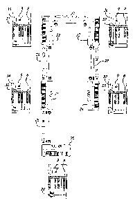
[0023] FIG. 2 is a schematic drawing of a network of musical instruments of
FIG. 1 with a partial detailed view of the panel and keyboard for each musical
instrument in the network.
[0024] FIG. 3 is a schematic drawing of another network of musical
instruments.
[0025] FIG. 4 is a plan view of a panel interface to be placed on top of a
panel
of a musical instrument in accordance with an embodiment of the present
invention.
DETAILED DESCRIPTION OF THE INVENTION
[0026] In the following description of preferred embodiments, reference is
made to accompanying drawings which form a part hereof and in which is shown
by
way of illustration specific embodiments in which the invention may be
practiced. It
CA 02530403 2005-12-21
WO 2005/004030 PCT/US2004/020070
is to be understood that other embodiments may be utilized and structural
changes
may be made without departing from the scope of the preferred embodiments of
the
present invention.
[0027] It should be also understood that in the following description the
instructor need not necessarily be a skilled musical teacher or performer. The
present
invention is well-suited to either a skilled or an unslcilled player as the
instructor,
because the instructor can be guided through the guide lamps and score display
as
well. Such an instructor can simply act as a facilitator for group playing.
[0028] FIG. 1 illustrates an electronic musical instrument 1 to be utilized in
the embodiments of the present invention. The electronic musical instrument 1
includes a keyboard 2 with a plurality of operating elements or lceys 3.
Although an
electronic keyboard instrument is illustrated in FIG. 1, the present invention
is
applicable with any other kind of electronic musical instrmnent, such as an
electronic
stringed instrument, as well as non-electronic musical instruments with MIDI
input
and output.
[0029] The lceys 3 of the electronic musical instrument 1 designate the pitch
of
each tone to be generated. When a given key is depressed, a depressed lcey
detection
circuit (not shown in FIG. 1) outputs lcey-on event data upon detection of the
depressed lcey, a lcey code indicative of the pitch of the depressed key and
lcey-off
event data upon release of the lcey. On the basis of performance data, a tone
source
circuit (not shown) generates a plurality of tone signals. The tone signals
are audibly
reproduced through a digital-to-analog converter and a sound system including'
speakers 4, 5. In this manner, a musical performance can be executed by a
player
through manual operation of the keys 3 of the keyboard 2.
[0030] The electronic musical instrument further includes a plurality of panel
switches 6 for inputting various lcinds of information. The panel switches 6
may
include tone color setting switches, numeric lceypads for setting values,
increment/decrement switches, automatic performance stant/end switch, overall
system setting switches and a performance guide function ON/OFF switch.
[0031] The electronic musical instrument 1 also includes a storage device 7
for external storage media. The storage device 7 may be external to the
electronic
musical instrument 1 or internal as illustrated. The storage device 7 may be
any one
CA 02530403 2005-12-21
WO 2005/004030 PCT/US2004/020070
of a number of conventional storage devices, such as a floppy disk device (as
shown),
a compact-dislc read-only memory (CD-ROM) device, a magneto-optical (MO) dish
drive, a digital versatile disk (DVD) drive or a flash memory card drive for
removable
flash memory cards or sticks. Storage media in the storage device 7 can store
various
performance data corresponding to a predetermined musical performance.
[0032] The electronic musical instrument 1 has two display devices for
guiding a musical performance. The first display device is a plurality of
guide lamps
8. Each guide lamp 8 is adjacent to a corresponding lcey 3 of the keyboard 2
and
includes an LED. Although a one-to-one correspondence between guide lamps and
keys is illustrated in FIG. l, the number of guide lamps may be varied. Once
the
performance guide function ON/OFF switch in the plurality of panel switches 6
is
turned ON, the LEDs are controlled to emit light. A display circuit (not
shown)
functions to light the appropriate LED. An illuminated guide lamp informs the
player
to depress the lcey corresponding to the lamp. A player releases the depressed
lcey
when the guide lamp stops emitting light. In this mamier, the guide lamps 8
guide a
player through a performance of musical notes comprising a musical
performance.
[0033] The second display device for guiding a musical performance is an
LCD panel 9 placed adjacent to the keys 3 of the keyboard 2. The LCD panel 9
can
display any number of graphical symbols for guiding performance. For example,
the
LCD can display a score of a musical performance as the music performance
proceeds. It can also display an image of part or all of the keyboard 2. The
keys of
the displayed lceyboard can be highlighted on the screen to guide the player
through
the performance. The LCD 9 can also display an image of both hands brought to
the
vicinity of the keys to be depressed with the fingers for depressing the keys
highlighted. As with the guide lamps 8, a display circuit functions to display
the
images on the LCD 9.
[0034] The electronic musical instrument 1 includes a communication
interface 10. The communication interface 10 can be connected to a
communication
network such as a LAN (local area network), the Internet or a telephone
networlc. The
communication network in turn is connected to a server computer, another
electronic
musical instrument or the like. Data from the server computer or the
electronic
CA 02530403 2005-12-21
WO 2005/004030 PCT/US2004/020070
musical instrument can be downloaded through the cormnunication network to the
electronic musical instrument 1 via the communication interface 10.
[0035] The electronic musical instrument 1 fiu-ther includes a MIDI
interface 11 which transmits and receives MIDI (Musical Instrument Digital
Interface) messages to and from other MIDI devices. The MIDI interface
includes
three MIDI terminals 11 a (MIDI IN), 11 b (MIDI OUT) and 11 c (MIDI THRU).
MIDI IN terminal 1 la receives MIDI messages from an external MIDI device such
as
a sequencer or another MIDI musical instrument. The MIDI OUT terminal 1 lb
sends
out MIDI messages generated by the electronic musical instrument 1. The MIDI
THRU terminal 11 c relays the MIDI messages received at the MIDI IN terminal
11 a
unchanged.
[0036] The electronic musical instrument 1 through the MIDI IN terminal 11 a
can receive a performance data set comprising a plurality of traclcs. Each
track
includes event data and timing data. The timing data indicates the timing to
read out
the event data. The event data includes key-on event data, lcey-off event
data, system-
exclusive data and the like. The lcey-on event data instructs to the
electronic musical
instrument 1 to begin sounding a note. The key-off event data instructs the
electronic
musical instrument to terminate sounding a note with or without a decay.
[0037] The system exclusive (SysEx) event data or message is used when
information other than performance information is transferred in the MIDI
format,
such as data unique to each manufacturer. For the electronic musical
instrument 1 to
receive a SysEx message, a SysEx receive switch from the panel switches 6 must
be
turned ON. When the SysEx receive switch is turned ON, the electronic musical
instrument 1 can receive SysEx messages generated by an external source.
[0038] A SysEx message can be used to control the ilhunination of the guide
lamps 8 of the electronic musical instrument 1. Yamaha's Clavinova line of
pianos
has the following SysEx messages for controlling the illumination of guide
lamps: (1)
Key LED Mode OFF and notes sound, (2) Key LED Mode ON and no notes sound or
(3) Key LED Mode ON and notes sound. If the message is Key LED Mode OFF and
notes sound, the LEDs of the guide lamps 8 will not emit light, but the lcey-
on event
data from the external source will instruct the electronic musical instrument
1 to
generate a tone corresponding to the lcey-on event data. If the message is Key
LED
CA 02530403 2005-12-21
WO 2005/004030 PCT/US2004/020070
Mode On and no notes sound, the LEDs will emit light.. The lcey-on event data
from
the external device triggers the corresponding LED to emit light, but it will
not
instruct the electronic musical instrument 1 to generate a tone. If the
message is Key
LED Mode On and notes sound, the LEDs of the guide lamps 8 will emit light
a.nd the
electronic musical instrument 1 will be instructed to generate tones by the
external
device.
[0039] These SysEx messages have been previously used in conjunction with
external sequencers to demonstrate the performance guidance function of an
electronic lceyboard instrument, for example in a retail store. The sequencer
is
connected to the electronic keyboard instrument in order to supply MIDI data
for
automatic performance by the instrument. The sequencer generates the Key LED
Mode ON messages to illustrate the sequential lighting of the guide lamps
during the
automatic performance so that customers can visualize the lceys which
correspond to
the performance.
[0040] To implement the embodiments of the present invention, the electronic
musical instrument of FIG. 1 is placed in a networlc with other electronic
musical
instruments. FIG. 2 illustrates one configuration of the network with
electronic
musical instruments 20, 21, 22, 23 and 24. Although electronic musical
instruments
20, 21, 22, 23 and 24 are identical, the network can comprise different types
of
musical instruments. Furthermore, the number of electronic musical instruments
can
vary from the five instruments illustrated in FIG. 2.
[0041] The configuration of the networlc in FIG. 2 is a MIDI daisy chain. A
MIDI daisy chain is a series of one-way connections. Specifically, the MIDI
OUT
terminal of electronic musical instrument 20 is connected to the MIDI IN
terminal of
electronic musical instrument 21 through MIDI cable 25. The MIDI THRU terminal
of electronic musical instrument 21 is in turn comlected to the MIDI IN
terminal of
the electronic musical instrument 22 through MIDI cable 26. Electronic musical
instruments 23 and 24 are connected to electronic musical instruments 22 and
23
respectively in the same manner through MIDI cables 27 and 28 as illustrated
in FIG.
2.
[0042] In the illustrated MIDI daisy chain network, the electronic musical
instrument 20 controls all the other electronic musical instruments 21, 22, 23
and 24.
CA 02530403 2005-12-21
WO 2005/004030 PCT/US2004/020070
For example, a key pressed on electronic musical instrument 20 will cause all
of the
other electronic musical instruments 21, 22, 23 and 24 to sound the tone
corresponding to the depressed lcey. The flow of MIDI data from electronic
musical
instrument 20 to the other electronic musical instruments 21, 22, 23 and 24 is
indicated by the arrows adjacent to MIDI cables 25, 26, 27 and 28 in FIG. 2.
Pressing
a lcey on any of the other electronic musical instruments 21, 22, 23 and 24
will only
generate a tone in the electronic musical instrument in which the lcey was
pressed,
because the output is only data passed through the instrument and not data
originated
at the instrument.
[0043] The daisy chain networlc of electronic musical instruments in FIG. 2
can be used to implement the first embodiment of the present invention for
group
instruction. Electronic musical instrument 20 is played by an instructor while
electronic musical instruments 21, 22, 23 and 24 are played by students. The
instructor depresses a lcey on his electronic musical instrument. This is
indicated in
FIG. 2 by the partial detailed view of the panel and keyboard of electronic
musical
instrument 20. The black dot on key 29 indicates that the instructor has
played note
C. Of course, more than one lcey at a time can be depressed in the present
embodiment.
[0044] The instructor's ley depression produces lamp control data that
illuminates in real-time the guide lamps 8 of each student's electronic
musical
instrument. This is achieved through a preparatory SysEx message.
Specifically,
prior to instruction, a facilitator disk is inserted in the storage device 7
of the
instructor's electronic musical instrument. The dislc includes a MIDI file
with a
preparatory SysEx message. If the data of the message is "I~ey LED Mode ON and
no notes sound," the LED(s) of each of the students' electronic musical
instruments
21, 22, 23 and 24 corresponding to depressed lcey 29 will be lit. This is
illustrated in
FIG. 2 by the partial detailed view of the keyboard and panel for each
student's
electronic musical instrument. Guide lamps 30, 31, 32 and 33 corresponding to
depressed lcey 29 of the instructor's electronic musical instrument 20 are lit
(illustrated as a dark guide lamp). The guide lamps will remain illuminated
until the
instructor releases key 29.
CA 02530403 2005-12-21
WO 2005/004030 PCT/US2004/020070
11
[0045] The illumination of guide lamps 30, 31, 32 and 33 provides a visual
correction between the note to be played and the instructor's verbal
instruction. For
example, the instructor can utilize the real-time illumination of the guide
lamps 30,
31, 32 and 33 to orient the students to the keys of the lceyboard. The
instructor can
also utilize the real-time illumination to explain the relationship between
the language
of music (e.g., the name of the note) and the corresponding lcey of the
keyboard.
[0046] The illuminated guide lamps also provide a visual indication for each
student to play the lcey corresponding to the illuminated guide lamp without
each
student having to loolc up at the instructor. Furthermore, unlike a standard
MIDI
performance message, the SysEx message will instruct electronic musical
instruments
21, 22, 23 and 24 to not generate a tone corresponding to depressed lcey 29.
Instead,
each student can depress the lcey corresponding to the illuminated guide lamp
to play
the note and independently generate a tone in a normal fashion. In other
words, the
MIDI data supplied to electronic musical instruments 21, 22, 23 and 24 are
used to
provide instruction but not note generation.
[0047] After the students have correctly depressed the lcey corresponding to
the illuminated guide lamp, the instructor can depress another key. This lcey
can
correspond to the next note of a musical performance. The instructor's manual
operation drives the guide lamps of each student's electronic musical
instrument
corresponding to the newly depressed lcey. In this manner, the instructor can
teach a
musical performance to a student or an entire group of students through the
use of
guide lamps of their respective instruments.
[0048] It should be noted that SysEx messages other than Key LED Mode ~N
and no notes sowed exist. For example, the SysEx message Key LED Mode ~N and
notes sound would cause LEDs to light and tones to be sounded at the students'
instruments. The SysEx message Key LED Mode OFF and note sound would cause
notes to be sounded in a conventional manner without lighting of LEDs. These
messages are not particularly useful for instruction.
[0049] However, there may be instances where the instructor wants to give
instruction by playing notes without the guides lamps being illuminated. If
the
instructor does not want the LEDs to light on each student's instrument (or
sound to
be generated), he must detach the MIDI cables connecting his instrument to the
CA 02530403 2005-12-21
WO 2005/004030 PCT/US2004/020070
12
students' instrument. A new SysEx message, Key LED Mode OFF and no notes
sound, has been defined overcome this disadvantage. The new message turns off
the
LEDs at each student's electronic musical instrument without the instructor
having to
detach any MIDI cables, such that there will be no response of any kind at
each
student's instrument in response to lcey depression at the instructor's
instrument.
Thus, there are two desirable modes for instruction in relation to SysEx
messages: 1)
Key LED Mode On and no notes sound and 2) Key LED Mode OFF and no notes
sound. The others are not generally desirable for instruction.
[0050] An aspect of the first embodiment further utilizes the LCD display on
each student's musical instrument to instruct music notation to the students.
The
student can not only learn the relationship between the note name and the lcey
to be
played, but also the correct music notation for the note. Because the score
display is
provided on each student's musical instrument, the students do not have to
look up at
any display device in front of the classroom and divert attention from the
electronic
musical instrument.
[0051] This aspect of the first embodiment is also illustrated in FIG. 2. For
this embodiment, a new SysEx message, Key LED Mode ON, no notes sound and
jump to score, has been defined. When the instructor plays note C by
depressing lcey
29, the guide lamp corresponding to the depressed lcey 29 on each student's
musical
instrument will be illuminated in the manner discussed above. The note name
and
musical notation corresponding to the depressed lcey 29 will also be displayed
on each
student's LCD display. FIG. 2 illustrates each student's musical display 34,
35, 36
and 37 showing a treble clef, with the note name (e.g., C note) and notation
corresponding to the depressed key. The same image can also appear on the
display
of the teacher's musical instrument.
[0052] It should be noted that the musical score display does not have to be
utilized in conjunction with the illumination of the guide lamps. A SysEx
message
can be defined to only "jump to score" and generate no sound and no LED
illumination. Also, the LCD display may display images other than a musical
score.
For example, the LCD display can display an image of the keyboard and two
hands.
The displayed keyboard can visually indicate depressed lcey 29 and further
indicate
the correct finger to play the note.
CA 02530403 2005-12-21
WO 2005/004030 PCT/US2004/020070
13
[0053] The method of the first embodiment can be further applied with stored
MIDI performance data such as has been previously utilized for self
instruction. As
discussed in the Description of Related Art, performance guidance functions
are
typically utilized with stored MIDI performance data. The stored MIDI data is
accessed by the electronic musical instrument, and the guide lamp for the
first note of
the performance is illuminated. If the player plays the note corresponding to
the
illuminated guide lamp, the note will sound and the guide lamp corresponding
to the
next note will be illuminated. Any accompaniment music associated with an
instructed note will also be played upon lcey depression. That is, the
automatic
performance data of the accompaniment music waits until the proper note is
played.
[0054] When stored MIDI data is used with the first embodiment, i.e., utilized
by the instructor to guide a performance, the guide lamp corresponding to the
first
note to be played is illuminated on the instructor's musical instrument, but
the
corresponding guide lamps on the students' electronic musical instruments are
not
illuminated because MIDI out signals are only generated upon lcey depression.
Only
after the instructor plays the first instructed note will the guide lamp of
each student's
musical instrument be illuminated, as discussed above. The students thus
receive the
visual indication only after the note is played which is not ideal for
following a
performance. The students do not receive any visual indication of the note to
be
played prior to the instructor playing the note. Furthermore, if the played
note
triggers accompaniment music, the accompaniment music is played before the
students play the illuminated note. Thus, the students do not get the benefit
of hearing
the accompaniment music as they play the note.
[0055] In yet another aspect of the first embodiment, the stored MIDI
performance data which instructs the next note or notes to be played is used
to light
not only the guide lamps of the instructor's electronic musical instrument,
but also the
guide lamps for each student's electronic musical instrument before the note
is to be
played. Furthermore, the instructor can control the progression of the guide
lamp
illumination and the performance in real-time. In this manner, the instructor
can
guide the students through, for example, a musical performance, and the
students can
receive the benefit of playing essentially simultaneously with the instructor
and
hearing the accompaniment music as they play the notes of the performance.
CA 02530403 2005-12-21
WO 2005/004030 PCT/US2004/020070
14
[0056] For this aspect of the first embodiment to be implemented, the
instructor inserts a storage media containing MIDI data of a musical
performance in
the storage device 7 of the instructor's electronic musical instrument.
Alternatively,
the MIDI data can be stored in a memory of the electronic musical instrument.
The
MIDI data for illuminating the guide lamps is on a given chamzel or traclc
called the
guide track. The data on the guide track is duplicated to another MIDI charnel
or
track by a sequences or similar device. The data on the new track is adjusted
such that
the guide lamps will blink for every note on the new track. This can be
achieved by
assigning a value of 1 for the velocity of every note on the track. Both of
these tracks
will be received by each student's electronic musical instrument to drive the
guide
lamps. The new track will provide the lighting before the instructor plays a
given
note, and the instructor's playing of the note will light the guide lamps of
each
student's instru~.nent as discussed below.
[0057] Specifically, when the new track of stored MIDI data is accessed by
the electronic musical instrument, the guide lamp corresponding to the first
note to be
played blinks in all of the electronic musical instruments in a network such
as in FICr.
2. Thus, the instructor and the students receive a visual indication of the
note to be
played. A student can play the indicated note at any time on his electronic
musical
instrument. However, only the instructor controls the progression of the
performance
and the illumination of the guide lamps. When the instructor plays the note
indicated
by the blinking guide lamp, the guide lamp corresponding to the played note
will
change from blinking to a solid light in each of the student's electronic
musical
instruments. This indicates to the student that the instructor has a played
the note.
The guide lamp corresponding to the next note to be played is then illuminated
as a
blinking light and any accompaniment music associated with the played note is
played
as well. In this manner, the students receive a visual indication of the notes
to be
played, but the instructor can control the progression of the musical
performance and
the illumination of the guide lamps in real-time, thereby guiding the students
through
the performance note-by-note.
[0058] The real-time instructor control of the progression of the musical
performance as well as the illumination of guide lamps can be particularly
useful for
group teaching. For example, the instructor can first ascertain whether all
the students
CA 02530403 2005-12-21
WO 2005/004030 PCT/US2004/020070
are ready to play the correct note indicated by the blinlcing guide lamp. Once
ascertained, the class can all then play the note corresponding to the
blinlcing guide
lamp at the same time. If the note is associated with accompaniment music, the
entire
class can hear the accompaniment music as they play the note. This instills
positive
reinforcement for the class.
[0059] Moreover, this aspect of the first embodiment can be particularly
useful for unskilled instructors. The guides lamps are illuminated in a
blinking
manner not only on each student's electronic musical instrument, but also on
the
instructor's electronic musical instrument. The instructor thus does not have
to have
any musical training to lead the student or students. He can simply follow the
blinking guide lamps at his discretion to facilitate group playing.
[0060] The MIDI daisy chain configimation of FIG. 2 is particularly
economical, because it can be accomplished without any external hardware other
than
one MIDI cable for each student's electronic musical instrument. It should be
noted
that the MIDI daisy chain configuration among numerous instruments is not
generally
recommended for normal MIDI performance applications due to MIDI delay
experienced between the instruments causing notes to be sounded at different
times at
the different instruments. However, the MIDI daisy chain configuration is
acceptable,
and preferred, for the embodiments of the present invention, because only lamp
control data for instructing the player at each instrument is used.
[0061] Network configurations other than the MIDI daisy chain can be used
for the embodiments of the present invention. FIG. 3 illustrates a hub-and-
spoke
configuration. One advantage of this configuration is the elimination of any
MIDI
delay found in the MIDI daisy chain configuration. Electronic musical
instrument 40,
used by the instructor, is the hub in the configuration while electronic
musical
instrmnents 41, 42 and 43, used by the students, are the spokes in the
configuration.
The electronic musical instruments are comzected through a controller, router
or the
like indicated by reference numeral 45. Specifically, the MIDI OUT terminal of
electronic musical instrument 40 is comlected to the MIDI IN terminal of
controller
45 through MIDI cable 46. The controller 45 has a number of MIDI OUT
terminals.
Three of its MIDI OUT terminals are connected to the MIDI IN terminals of
CA 02530403 2005-12-21
WO 2005/004030 PCT/US2004/020070
16
electronic musical instruments 41, 42 and 43 through cables 47, 48 and 49,
respectively.
[0062] As in the MIDI daisy chain configuration of FIG. 2, the electronic
musical instrument 40 in FIG. 3 controls all the other electronic musical
instruments
41, 42 and 43. For example, a key pressed on electronic musical instrument 40
will
cause all of the other electronic musical instruments 41, 42, and 43 to sound
the tone
corresponding to the depressed lcey. The flow of MIDI data from electronic
musical
instrument 40 to the other electronic musical instruments 41, 42 and 43 is
indicated by
the arrows adjacent to MIDI cables 46, 47, 48 and 49 in FIG. 3. It should be
noted
that the configuration of FIG. 3 is not the preferred due to the additional
hardware
(e.g., controller 45) that is needed to implement the configuration.
[0063] A second embodiment of the present invention is directed to remote
instruction of a student or a group of students via a communication network
such as
the Internet. In this embodiment, an instructor plays notes on a musical
instrument
connected to the Internet. Students, at different locations, are also
coimected to the
Internet through communication interface 6 of their respective musical
instruments.
Some of the students may be connected to the Internet through a computer
coupled to
their respective electronic musical instruments.
[0064] MIDI data is sent from the instructor's electronic musical instrument
through the Internet and is received by each student's electronic musical
instrument or
computer. The MIDI data comprises the data to perform the instruction methods
discussed above. For example, as the instructor plays a note, MIDI data
comprising
lamp control data, as opposed to note playing data, is transmitted to the
students'
musical instruments over the Internet. The lamp control data drives the guide
lamps
on each student's instrument to visually indicate the played note, but without
generating a tone at the student's instrlunent. The students can then play the
visually
indicated note and generate a tone. Furthermore, the MIDI data may comprise
data
for controlling the score display to provide musical notation of the played
notes. The
second embodiment can also be utilized with stored performance data as
discussed
above with respect to the first embodiment.
[0065] It should be noted that other data may be sent in conjunction with the
MIDI data over the Internet. For example, streaming video data may be sent in
CA 02530403 2005-12-21
WO 2005/004030 PCT/US2004/020070
17
conjunction with the MIDI data to provide a real-time image of the performer
on the
computer monitors of the students or possibly on the LCD panel 9 of the
electronic
musical instruments. Such data with the MIDI data provides a visual context
for the
remote instruction.
[0066] Although the second embodiment has been described with the Internet
as the communication networlc, other networks may be used. The communication
networlc may be a wireless communication networlc, a public telephone line
network,
a LAN or the lilce. In the case of a wireless communication networlc, the
electronic
musical instrument's communication interface sends and receives electrical,
electromagnetic or optical signals carrying data, such as the lamp control
data.
[0067] The embodiments of the present invention have been described with a
instructor teaching a student or a group of students. The group, however, does
not
have to be made of an teacher with students, a performer with fans or a
virtuoso
master with apprentices. The embodiments of the present invention open up new
group music possibilities that go beyond instructional settings.
[0068] For example, the embodiments of the present invention can be applied
in a hospital setting. A group of patients can be led by a unslcilled hospital
staff
person to 'promote wellness or healing. The embodiments of the present
invention can
also be applied in a retirement community setting. A facilitator in a
retirement
community (such as a staff person or even one of the retirees) can lead a
group of
retirees through a musical program designed to improve the retirees' quality
of life.
The embodiments of the present invention can even be applied, through a
communication network, in the homes of a group of friends who want to learn to
play
music. For example, each week, one friend can act as a facilitator by leading
the
group through a musical performance.
[0069] It should be noted that these group music possibilities are not limited
to
learning a musical performance. Such programs may be involve learning a few
notes,
using relaxation techniques with music or teaching young students to
concentrate
through the rewards of hearing tones generated by an instrument.
[0070] It should be noted that current electronic musical instruments have
many features to enable music-malting by individuals ranging from beginners to
virtuosos. As a result, the panel of an electronic musical instrument may
contain a
CA 02530403 2005-12-21
WO 2005/004030 PCT/US2004/020070
18
umnber of different switches, buttons, lcnobs and the like. If the user is an
unskilled
player or a beginner as discussed above, the panel may be intimidating with
many
different panel members (especially those not intended for his use). However,
to
change the panel configuration for each group of players can be very time-
consuming
and expensive.
[0071] Fig. 4 illustrates an embodiment of the present invention for
electronic
keyboard instruments (although the present invention is applicable to other
types of
musical instruments). Panel 60 is a panel of an electronic keyboard musical
instnunent, and interface 61 is designed to be placed on the panel as
indicated by the
dotted lines in FIG. 4. The panel 60 includes a LCD panel 62, a data wheel or
knob
63 for controlling information on the LCD panel 62 and a fade in/out button
64.
Control section 65 refers to a group of buttons relating to choosing a style
(e.g., pop,
Jazz, Latin) for auto accompaniment. Reference numeral 80 refers to a group of
buttons relating to voice effect, such as reverb, variation and harmony echo.
Reference numeral 81 refers to a group of buttons relating to the menu (demo,
help,
function) and digital studio (sound creator, digital recording and mixing
console).
[0072] The LCD panel 62 includes various sections 66, 67 and 68 providing
information relating to corresponding switches, buttons, lcnobs and the lilce.
For
example, section 66 relates to the style for the auto accompaniment as
controlled by
control section 65. The panel 60 also includes writing to explain the panel
members.
For example, reference numeral 69 refers to "Registration Memory" for the
group of
buttons directly underneath it.
[0073] The interface 61, which can be made of plastic, is placed over panel 60
and is removable. It features basic functions in an inviting, easily
understood manner.
The interface 61 has cut-outs for certain panel members. For example, cut-out
71 is
designed to border the LCD 62. Other panel members are hidden by the interface
61
to simplify the panel 60. These panel members may refer to advance features or
may
be confusing to a beginner or wslcilled player. For example, the interface 61
covers
the data wheel 63 and the fade in/out button 64. It also covers the group of
buttons
relating to voice effect as indicated by reference numeral 80 and the group of
buttons
relating to the menu and digital studio as indicated by reference numeral 81.
It should
CA 02530403 2005-12-21
WO 2005/004030 PCT/US2004/020070
19
be noted that as the player proceeds through the learning process, sections of
the
interface 61 can be removed to show previously hidden panel members.
[0074] The interface 61 also clusters panel members having like functions
through the use of color coding and easily understood terms or phrases. For
example,
control section 65 which controls the style for the auto accompaniment is
simply
renamed "STYLES" 72 in a large font and the entire group of buttons is
surrounded
by cut-outs 75 in a bright color 70 (indicating by the lughlighting).
Similarly, buttons
relating to different sounds is named "SOUNDS" 73 acid is surrounded by cut-
outs in
a different, bright color 74 (indicated by the different highlighting). The
group of
buttons relating to "Registration Memory" is in a yet another different color
78, and
the phrase "Registration Memory" has been covered by the interface 61 and
replaced
with the easier-to-understand phrase "MY SETTINGS" 76. In this manner, an
instructor can refer to a color section or a topic heading (e.g., STYLES) to
orient the
students to a given section of panel 60. The simple heading is also easier for
the
student to understand the function of the panel member or members.
[0075] Moreover, the color coding on interface 61 can be tied to the LCD
panel 62. The color coding is extended from a given group of buttons to LCD
panel
display buttons for controlling the display. For example, the color coding 70
for the
STYLES panel members is extended on the interface 61 to LCD panel display
button
82. Similarly, the color coding 74 for the SOUNDS panel members and the color
coding 78 for the MY SETTINGS panel members are extended to LCD panel display
buttons 83 and 84 respectively.
[0076] The display buttons 82, 83 and 84 relate to sections 66, 67 and 68 of
the LCD panel 61 that provide information relating to the group or cluster of
panel
members. These sections of the LCD panel can also be color coded. For example,
section 66 can be the same color as the color 70 on the interface 61 for the
STYLES
panel members. Similarly, sections 67 and 68 can be the same color 74 and 78
on the
interface 61 for the SOUNDS and MY SETTINGS panel members, respectively. By
color coding a group or cluster of related buttons and then tying the group
through
color to a display button and a section of the LCD panel, a beginner can
easily
connect the related buttons to the information provided in the section of the
LCD
panel. Moreover, the instructor can easily orient the students to a section of
the LCD
CA 02530403 2005-12-21
WO 2005/004030 PCT/US2004/020070
panel by simply referring to the color. Aside from color coding, the LCD panel
may
also repeat heading names such as STYLES for even easier reference. It should
be
noted that different types of coding other than color coding may be used, such
as
hatching or texture coding.
[0077] The present invention can be modified depending on the age group of
the students or the market. For example, for seniors, the font size of some of
the
headings can even be larger. Figures of objects can also be used to
communicate the
function of a panel member. For example, on the interface 61 in FIG. 4, a
figure 77 of
the right hand is used to communicate the function of the panel member. For
young
students, figures from cartoons, television shows and the like may used in
conjunction
with color coding, and more of the panel members may be hidden to focus young
students on just a few panel members.
[0078] The present invention can also be used in conjunction with the first
and
second embodiments of the present invention. For example, the instructor can
refer to
the interface 61 to orient the students to panel before the performance. The
teacher
can then instruct the students to press certain buttons necessary for the
performance.
Some students can be directed through the interface 61 to provide a certain
drum
sound and other students can be directed to provide other sounds. Then, the
instructor
can use the first and second embodiments to lead the students through a
performance
that combines all the sounds.
[0079] Although the present invention has been fully described in comlection
with the preferred embodiments thereof with reference to the accompanying
drawings, it is to be noted that various changes and modifications will become
apparent to those slcilled in the art. Such changes and modifications are to
be
understood as being included within the scope of the present invention as
defined by
any appended claims.