Note: Descriptions are shown in the official language in which they were submitted.
CA 02530620 2005-12-22
WO 2005/003642 PCT/EP2004/002080
1
Apparatus and method for installing functional non
architectural elements
This invention concerns an apparatus for mounting and covering
functional non-architectural elements on buildings, and in
particular for mounting and covering an external water tank of
a prior-art solar panel system to produce domestic hot water.
Moreover, the invention concerns a method for aesthetically
harmonising covering means of functional non-architectural
elements with the buildings in which the latter are comprised.
Solar panels are heat collectors suitable for transforming the
solar electromagnetic energy directly in thermal energy and
are mounted on the roofs of buildings or on other external
portions of the latter wherein exposure to.the solar radiation
is at its maximum.
Each heat c~llector comprises an exchange circuit that extends
as far as a tank containing water to be heated. In the
exchange circuit, an exchange fluid (for example glycol)
circulates that heats up in the heat collector due to the heat
received from the solar radiation and cools around the walls
of the tank, thus transferring heat to the water contained
therein. Heat collectors also exist in the prior art wherein
the water to be heated rather than the exchange fluid
circulates directly.
To-.reduce the length of the connecting pipes placed between
the heat collectors and the relative tanks, the latter are
arranged on the roofs of the buildings as close as possible to
the collectors, in a position that is immediately overhead in
relation to the latter.
As a result, the tanks are installed in a position close to
the ridge of the roof and are therefore rather visible, which
is aesthetically unacceptable:
For this reason, the use of the solar panels of the type
described above is still rare, despite the considerable
advantages of such panels both in terms of protection of the
CONFIRMATION COPY
CA 02530620 2005-12-22
WO 2005/003642 PCT/EP2004/002080
2
environment through their exploitation of solar energy and the
considerable operational economy.
FR 2568990 and NL 1004031 disclose structures covering water
tanks comprised in solar energy systems for producing domestic
hot water. These structures are made in the shape of
architectural elements, namely a prism-shaped canopy (FR
2568990) and an enlarged and modified ridge tile (NL 1004031).
Both structures are only intended, and consequently shaped,
for covering a water tank horizontally arranged onto a roof.
Such functional elements, for example the external units of
air-conditioning systems, are made aesthetically pleasing so
that can increasingly be used in outer zones of residential
buildings.
An object of this invention is to improve the apparatuses for
mounting and covering functional elements that can be placed
outside buildings.
Another object is to provide an apparatus for covering a water
tank of a system producing domestic hot water by means of
solar panels so as to hide the tank from view and
simultaneously firmly anchor the tank to the roof of the
relative building.
Another further object is to provide an apparatus for mounting
on roofs functional non-architectural elements, for example
external units of air-conditioning systems, which enables the
latter to be harmonised with the buildings.
A yet further object is to provide a substantially inexpensive
and simple method for harmonising covering structures of
functional non-architectural elements mounted on roofs of
buildings with the architectural style of the buildings
themselves.
According to a first aspect of the invention, there is
provided apparatus, comprising covering means suitable for
covering a water tank which can be mounted onto a external
portion of a building, said covering means being made in the
CA 02530620 2005-12-22
WO 2005/003642 PCT/EP2004/002080
3
shape of an architectural component, characterized in that
said apparatus further comprises angular positioning means so
configured as to keep said tank in a substantially vertical
position.
Owing to this aspect of the invention, it is possible to
position the water tank in a substantially vertical position
regardless of the slope of the portion of building onto which
the tank has to be mounted. This is particularly useful when
the water tank is comprised in a solar panel system for
producing domestic hot water, since a vertical position of the
tank ensures a more effective heat exchange, thus improving
the efficiency of the solar panel system.
According to a second aspect of the invention, there is
provided apparatus, comprising covering means suitable for
covering a component of an air-conditioning system which can
be mounted onto an external portion of a building, said
covering means being made in the shape of an architectural
component.
Owing to this aspect of the invention a functional element
such as an external unit of an air-conditioning system can be
installed outside a building in a way that is substantially
harmonious with the aesthetic features of the latter.
According to a third aspect of the invention, there is
provided a method, comprising:
- reproducing a selected part of a building to get an image
therefrom on layer means;
- applying said onto support surface means surrounding a
functional non-architectural element.
Owing to this aspect of the invention, it becomes possible to
provide a covering structure, for example of a water tank or
an external unit of an a'i.r-conditioning system, with the same
architectural features of the building onto which the covering
structure is mounted.
CA 02530620 2005-12-22
WO 2005/003642 PCT/EP2004/002080
4
The invention may be better understood and carried into effect
by referring to the enclosed drawings that show non-limiting
embodiments, by way of examples, wherein:
Figure 1 is an incomplete and fragmentary perspective view of
an external arrangement of tanks of a solar-energy system for
producing domestic hot water according to the prior art;
Figure 2 is an incomplete, fragmentary and partially sectioned
perspective view of an apparatus according to the invention;
Figure 3 is an incomplete, fragmentary and partially sectioned
l0 perspective view of an apparatus according to the invention,
in a further embodiment;
Figure 4 is an incomplete, fragmentary and partially sectioned
perspective view of an apparatus according to the invention,
in an other further embodiment;
Figure 5 is an incomplete, fragmentary and partially sectioned
perspective view of an apparatus according to the invention,
in an yet further other embodiment;
Figure 6 is a schematic side view of the apparatus in Figure
2, illustrating a constructional detail of the latter;
Figure 7, is a schematic side view illustrating a further
embodiment of the constructional detail of Figure 6;
Figure 8 is a schematic side view illustrating a further other
embodiment of the constructional~detail of Figure 6;
Figure 9 is a perspective view illustrating a yet further
other embodiment of the constructional detail shown in Figure
6;
Figure 10 is a side view of the constructional detail shown in
Figure 9;
Figure 11 is a front view of the constructional detail shown
in Figure 10;
Figure 12 is a rear view of the constructional detail shown in
Figure 10;
Figure 13 is a plan view of the constructional detail shown in
Figure 10;
CA 02530620 2005-12-22
WO 2005/003642 PCT/EP2004/002080
Figure 14 is an incomplete, fragmentary and partially
sectioned perspective view illustrating a further other
embodiment of the apparatus according to the invention;
Figure 15 is a schematic perspective, fragmentary and
5 incomplete view illustrating a step of a method according to
the invention;
Figure 16 is a schematic perspective view illustrating an
other step of the method according to the invention;
Figure 17 is a schematic perspective, fragmentary and
incomplete view illustrating a further step of the method
according to the invention;
Figure 18 is a schematic perspective, fragmentary and
incomplete view illustrating a yet further step of the method
according to the invention;
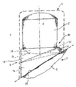
In Figures 2 to 5, on a tiled 8 roof T of a house A a mounting
and covering apparatus 1 of a tank 2 comprised in a prior-art
solar panel system R producing domestic hot water to be
supplied to the house A. The tank 2 is arranged to contain the
water to be heated and the latter is fed by means of conduits
4 to a pair of prior-art heat collectors 3 comprising a pipe
with a helical or coiled configuration that is not shown.
The apparatus 1 located on the roof T immediately above the
collectors 3 may have the shape of a chimney cap C, skylight
Z or attic skylight M, and is defined by a plurality of walls
6. Each wall 6 consists of one or more panel elements 7, made
for example of fibreglass, A.B.S., polycarbonate, polystyrene,
sheet metal, or another material that resists atmospheric
agents, the visible faces of which are decorated and/or shaped
in such a way as to imitate prior-art building bricks. In
particular, the panel elements 7 can be made in such a way as
to reproduce the ornamental features of the external walls of
the house A or of the roof tiles 8. In an embodiment that is
not shown, the walls 6 are also made from prior-art building
bricks .
CA 02530620 2005-12-22
WO 2005/003642 PCT/EP2004/002080
6
By suitably making the walls 6 of the apparatus 1 in the shape
of a chimney cap C the latter can be installed on a sloping
part S or a ridge K of the roof T.
In the apparatus 1 made in the shape of a skylight L and/or in
the shape of an attic skylight M one of the walls 6 comprises
a real or simulated window F, made in harmony with the
aesthetic features of the house A.
When the apparatus 1 is shaped like a chimney cap C or a
skylight L, in the latter the tank 2 is kept in a vertical
position by means of fixing means described below. When the
apparatus 1 is shaped like an attic skylight M, the tank 2 is
spread horizontally and is fixed to the roof T with prior-art
fixing means that is not shown.
In Figure 6, the tank 2, accommodated inside the apparatus 1
made in the shape of a chimney cap C, is stably positioned by
angular positioning means comprising an adjustable angular
positioning element 9, having a quadrilateral shape and
comprising a hollow base portion 10 that is made integral with
the sloping part S of the roof T by means of prior-art fixing
means, that are not shown. On the base portion 10 a movable
portion 10' is hinged by means of a hinge 11, said movable
portion 10' having a shape and dimensions such as it can be
retractably inserted inside said base portion 10. The movable
portion 10' furthermore comprises a circular opening 60,
arranged horizontally to receive a generally convex end
portion 13 of the tank 2. Inside the movable portion 10',
concave stop elements 12 are inserted that are arranged to
receive the end portion 13.
In use, after fixing an anchoring base face 70 of the base
portion 10 to the sloping part S, the movable portion 10' is
made to rotate on the hinge 11 until it reaches a desired
position P, wherein the movable portion 10' is orthogonal as
regards a longitudinal axis X of the tank 2. The latter can
then be inserted into the movable portion 10' with the end
CA 02530620 2005-12-22
WO 2005/003642 PCT/EP2004/002080
7
portion 13 resting on the stop elements 12. In this way, the
longitudinal axis X of the tank 2 can be kept vertical
regardless of the angle of inclination of the sloping part S.
The adjustable angular positioning element 9 can also be used
for the apparatus 1 made in the shape of a skylight Z.
Note that the structure of the above disclosed angular
positioning means enables a tank 2 to be mounted on sloping
parts S that have inclinations comprised within a wide range
of values.
In Figure 7, a further adjustable angular positioning element
14 is provided that is arranged to stably position the tank 2
accommodated in the apparatus 1 in the shape o.f a chimney cap
C, on the ridge K of the roof T. The further adjustable
angular positioning element 14 comprises a pair of further
movable portions 15, 15' between which a hollow support
portion 16 is comprised. The support portion 16 has dimensions
that enable it to be retractably housed into the further
movable portions 15, 15' and furthermore comprises a circular
opening 50, arranged horizontally to receive the end portion
13 of the tank 2. Inside the support portion 16 stop elements
12 are arranged that are shapingly coupled with the end
portion 13.
The further movable portions 15, 15' are hinged on the support
.portion 16 by means of relative hinges 11, the axes of which
run parallel in an approximately middle portion of the support
portion 16. In this way, the further movable portions 15, 15'
are set in mutually opposite directions.
In use, after horizontally positioning the support portion 16
of the further adjustable angular positioning element 14
straddling the ridge K, the further movable portions 15, 15'
are made to rotate until a further base anchoring face 80, 80'
of the latter is brought into contact with the respective
opposite sloping parts S, S'. In this way, the further
adjustable angular positioning element 14 can be adapted to
CA 02530620 2005-12-22
WO 2005/003642 PCT/EP2004/002080
8
the width of an angle H of the ridge K, so as to enable the
support portion 16 to take up a horizontal position and thus
keeping the longitudinal axis X of the tank 2 in a vertical
position.
The further adjustable portions 15, 15' are then made integral
with the sloping parts S, S' by prior-art fixing means that
are not shown and the tank 2 is inserted into the support
portion 16, with the end portion 13 resting on the stop
elements 12.
Figures 9 to 13 show a yet further adjustable angular
positioning element 90, that is arranged to stably position
the tank 2 accommodated in the apparatus 1 in the shape of a
chimney cap (not shown). The further adjustable angular
positioning element 90 comprises a substantially rectangle-
shaped anchoring plate 91 whose further anchoring base face 92
can be fixed to the sloping part S, shown by means of a broken
line.
A further base portion 93 leads away from an approximately
central portion of the anchoring plate 91, said further base
portion 93 having a longitudinal section that is substantially
shaped as a circular sector. In two opposite side faces 98 of
the further base portion 93 a curved plate 94 is provided, in
which a plurality of holes 97 is obtained. A yet further
movable portion 95 is hinged to the further base portion 93 by
means of a hinge 11, said yet further movable portion 95
having a shape and dimensions that enable it, when rotating
along the hinge 11, to partially cover the further base
portion 93. In two opposite further side faces 100 of the yet
further movable portion 95 further holes 99 are obtained,
which are level with the holes 97 of the further base portion
93. The yet further movable portion 95 furthermore comprises a
square opening 96, arranged horizontally to receive an end
portion, not shown, of the tank 2. Inside the yet further
CA 02530620 2005-12-22
WO 2005/003642 PCT/EP2004/002080
9
movable portion 95, concave stop elements 12 are inserted that
are arranged to receive the end portion.
In use, after fixing the further anchoring base face 92 of the
anchoring plate 91 to the sloping part S by means of prior art
fixing means, that is not shown, the yet further movable
portion 95 is made to rotate on the hinge 11 until it reaches
a desired position Q, wherein the yet further movable portion
95 is at right angles to the longitudinal axis X of the tank
2. The position Q, once reached, can be kept by inserting
prior art fixing means, that is not shown, through the further
holes 99 and the corresponding holes 97.
The tank 2 can then be inserted into the yet further movable
portion 95 with the end portion resting on the stop elements
12. In this way, the longitudinal axis X of the tank 2 can be
kept vertical regardless of the angle of inclination of the
sloping part S.
In Figure 8 a fixed angular positioning element 17 is
provided, usable to stably position on the sloping part S the
tank 2 accommodated in the apparatus 1 made in the shape of a
chimney cap C or a skylight Z. The fixed angular positioning
element 17 is made in the shape of a quadrilateral having a
triangular longitudinal section and a circular opening 40
arranged horizontally to accommodate the end portion 13. In
use, a base face 18 of the fixed angular positioning element
17 opposite the circular opening is made integral with the
sloping part S by prior-art fixing means that are not shown.
The end portion 13 is then inserted in the circular opening 40
and is rotated in the latter until the tank 2 reaches a
position wherein the longitudinal axis X of the latter is
arranged vertically.
. It is pointed out that the vertical attitude of the tank 2
which is obtainable through the angular positioning elements
(9; 14; 17; 90) shown in Figures 6-13 enables a more effective
heat exchange to be achieved.
CA 02530620 2005-12-22
WO 2005/003642 PCT/EP2004/002080
As shown in Figure 14, also a non-architectural functional
element other than the tank 2, for example an external unit 19
of an air-conditioning system Z, can be housed inside the
apparatus 1. The external unit 19, made integral with the
5 sloping part S by means of prior-art fixing means, that is not
shown, is accommodated inside the apparatus 1 made for example
in the shape of a chimney cap C. In the latter, walls 6 that
are opposite one another and are situated near a fan 30 of the
external unit 19 each comprise a grille 20 for enabling air to
10 be taken from the external environment. In an alternative
embodiment, that is not shown, intended for external units of
air-conditioning systems provided with fans having a
vertically arranged axis, the apparatus 1 can be made in the
shape of a chimney cap C having an open top end, which may be
provided with a grille. In this way it is for example possible
to provide an air-conditioning system for buildings subject to
artistic protective constraints and which cannot therefore
accommodate external structures that are aesthetically
disturbing.
The apparatus 1 may furthermore be made, in addition to the
described forms of chimney cap C, skylight L and attic
skylight M, also in the form of further architectural
components, for example verandas or balconies, that are not
shown or disclosed in detail, that are selected on the basis
of the dimensions and contour of the non-architectural
functional elements to be installed on the outside of
buildings.
Figures 1_5 and 16 show a well-known device, for example a
camera 201, by means of which a picture I, shown by means of a
broken line, is obtained from a front portion R of a house A.
The picture I can be taken so as to portray, for example, a
decorative pattern D comprised in the house A. Once obtained,
the picture I can be transferred, by means of prior art
techniques that are not disclosed in detail, onto a supporting
CA 02530620 2005-12-22
WO 2005/003642 PCT/EP2004/002080
11
film F, for example made from plastics, thus forming a
covering layer Y.
Figure 17 and 18 show a procedure for fitting the covering
layer Y onto a covering structure installed on a roof T, said
covering structure housing a water tank (not shown) comprised
in a solar panel system R for producing domestic hot water.
The covering structure, for example, is the above disclosed
apparatus 1 made in the shape of the chimney cap C.
The covering layer Y, whose shape and dimensions are selected
so as to fully wrap the walls 6 of the chimney cap C, is wound
around the latter according a rotatory verse shown by the
arrow F1, so as to enable two curved edges 202, 203, obtained
in opposite ends of the covering layer Y, to mutually come
into contact. Once the edges 202, 203 have been made to
reciprocally engage, a prior art top element 204 is applied
onto the chimney cap C, thus ensuring the covering layer Y to
be firmly blocked thereon. In a further embodiment, not shown,
the face of the covering layer Y opposite the picture I is
provided with an adhesive layer, which can be fixed to the
walls of a covering structure.
The disclosed method becomes very useful when the house A is
an ancient one, which makes significantly difficult and/or
expensive manufacturing covering structures according to the
architectural style and/or the aged appearance of the house.
The above disclosures show that the apparatus 1 provided by
the invention in all its possible architectural embodiments is
always includable in a building and is therefore suitable for
housing a non-architectural functional element, such as for
example a water tank or an external unit of an air-
conditioning system, making the latter aesthetically
harmonised with the building for which it is intended. This
enables the significant aesthetic damage to be avoided that is
for example produced by the water tanks of solar panels
CA 02530620 2005-12-22
WO 2005/003642 PCT/EP2004/002080
12
systems mounted on the roofs of buildings provided for by the
state of the art illustrated in Figure 1.
Moreover, according to the method provided by the invention,
it becomes possible to harmonise any kind of covering means of
non-architectural elements with the.building onto which the
elements, and the respective covering means, are mounted. This
result can be achieved by reproducing onto the covering means,
in a substantially inexpensive manner, the architectural style
occurring in the respective building.