Note: Descriptions are shown in the official language in which they were submitted.
CA 02530872 2005-12-28
WO 2005/005769 PCT/US2004/018289
-1-
EARTH PENETRATING ROTARY DRILL BIT WITH HELICAL PORTS
BACKGROUND OF THE INVENTION
The invention pertains to an earth penetrating rotary drill bit that
has a hard member at the axial forward end thereof. More specifically, the
invention pertains to an earth penetrating rotary drill but that has a hard
member at
one end thereof and wherein the rotary drill bit contains debris (or dust)
ports for
evacuating dust and debris from the vicinity of the drilling operation.
The expansion of an underground coal mine requires digging a
tunnel that initially has an unsupported roof. To provide support for the
roof, an
earth penetrating rotary drill bit (e.g., a roof drill bit) is used to drill
boreholes,
which can extend from between about two feet to about (or even greater than)
twenty feet, into the earth strata. In this regard, the earth penetrating
drill bit is
connected to a drill steel. The drill steel is connected to a rotary driver.
The rotary
driver powers the earth penetrating drill bit so as to drill the earth strata.
Roof
bolts are affixed within the boreholes and a roof support (e.g., a roof panel)
is then
attached to the roof bolts. Examples of a conventional roof drill bit with an
axial
forward slot that carries a blade style hard insert are the KCV4-1RR and KCV4-
1
1/32RR Roof RocketTM drill bits made by Kennametal Inc. of Latrobe,
Pennsylvania, USA and shown in U.S. Patent No. 5,172,775 to Sheirer et al.
During the drilling operation, rotary drill bits generate debris. This
debris can take the form of dust-like fine particles. The debris may also
exist as
larger particles. During the drilling operation, this debris is evacuated
under the
influence of a vacuum from the vicinity of the drilling operation through
debris
ports (or dust ports) contained in the body of the rotary drill bit. On
occasion
during the drilling operation, a rotary drill bit can generate a large enough
volume
of debris such that the rotary drill bit is unable to evacuate the debris
quickly
enough from the vicinity of the drilling operation to maintain the efficient
operation of the rotary drill bit. When the debris cannot be adequately
evacuated
from the vicinity of the drilling operation, several consequences can occur.
One such consequence is that the speed at which the rotary drill bit
operates, and hence the drilling rate, must be reduced so as to accommodate
the
CA 02530872 2005-12-28
WO 2005/005769 PCT/US2004/018289
-2-
debris. By reducing the speed of the rotary drill bit due to the inability of
the
rotary drill bit to evacuate debris, the operator is limited in being able to
operate
the rotary drill bit at its optimum capability. It would be desirable to
provide an
improved rotary drill bit that better evacuates drilling debris so as to
enhance the
ability of the rotary drill bit to operate at a higher speed.
Another such consequence of the inability to adequately evacuate
debris from the vicinity of the drilling operation is that the rotary drill
bit tends to
stick in the bore hole. This causes the drilling operation to become less
consistent
and rougher. It would thus be advantageous to provide an improved rotary drill
bit
that better evacuates drilling debris from the vicinity of the drilling
operation so as
to provide for the smoother operation of the rotary drill bit.
Yet another such consequence of the inability to adequately
evacuate debris from the vicinity of the drilling operation is that the rotary
drill bit
tends to overheat. This is due to the presence of drilling debris that
increases the
friction between the rotary drill bit and the earth strata (included the
debris). It
would thus be advantageous to provide an improved rotary drill bit that better
evacuates drilling debris from the vicinity of the drilling operation so that
the
rotary drill bit operates cooler, i.e., operates at lower temperature.
Overall, it can be seen that there would be a number of advantages
associated with being able to provide an improved earth penetrating rotary
drill bit
that is able to better evacuate debris from the vicinity of the drilling
operation.
The advantages include allowing for the rotary drill bit to smoothly operate
at
higher drilling rates and yet still be at a lower operating temperature.
SUMMARY OF THE INVENTION
In one form thereof the invention is a drill bit for drilling earth
strata whereby debris is generated during the drilling operation. The drill
bit
comprises a drill bit body that has a side wall and opposite ends wherein a
distal
one of the opposite ends of the drill bit body receives a cutting insert. The
drill bit
body contains a helical debris port in the side wall thereof and a helical
scallop
surrounds the debris port. The helical scallop is proximate to the cutting
insert so
CA 02530872 2005-12-28
WO 2005/005769 PCT/US2004/018289
-3-
that debris from the drilling operation impinges upon the helical scallop
whereby
the helical scallop directs the debris into the helical debris port.
In yet another form thereof, the invention is a drill bit for drilling
earth strata so as to generate debris. The drill bit comprises a drill bit
body that
has a side wall and opposite ends wherein a distal one of the opposite ends of
the
drill bit body receives a cutting insert. The drill bit body contains a
helical debris
port in the side wall thereof and a helical scallop surrounds the debris port.
The
distal end of the drill bit body presents a feeder surface wherein the feeder
surface
is adjacent to the cutting insert. Debris from the drilling operation
impinging upon
the feeder surface so that the feeder surface feeds the debris into the
helical scallop
whereby the helical scallop directs the debris into the helical debris port.
In yet another form thereof, the invention is a drill bit that
comprises a drill bit body that has a side wall and opposite ends wherein a
distal
one of the opposite ends of the drill bit body receives a cutting insert. The
drill bit
body contains at least two helical debris ports in the side wall thereof, and
a
helical scallop corresponding to each one of the helical debris ports. Each
one of
the helical scallops surrounds its corresponding debris port so as to define
the
periphery thereof.
In still another form thereof, the invention is a drill bit that
comprises a drill bit body that has a side wall and opposite ends wherein a
distal
one of the opposite ends of the drill bit body receives a cutting insert. The
drill bit
body contains a helical debris port in the side wall thereof. The drill bit
body
contains a helical scallop surrounding each one of the helical debris ports
wherein
the scallop defines a periphery of the debris port. The helical scallop has a
pitch
ranging between about 3 inches (about 7.62 centimeters) and about 15 inches
(38.1 centimeters).
In one form thereof, the invention is a cold-formed rotary drill bit
body that comprises a side wall wherein the side wall contains a helical
scallop
and the helical scallop presents a pitch ranging between about 3 inches (about
7.62
centimeters) and about 15 inches (38.1 centimeters). The side wall contains a
helical debris port wherein the helical scallop surrounds the helical debris
port.
CA 02530872 2011-04-29
68188-229
-4-
The bit body further includes opposite ends wherein a distal one of the
opposite ends
containing a slot for receiving a cutting insert.
In yet another form thereof the invention is a cast rotary drill bit body
that comprises a side wall wherein the side wall contains a helical scallop
and the
helical scallop presents a pitch ranging between about 3 inches (about
7.62 centimeters) and about 15 inches (38.1 centimeters). The side wall
contains a
helical debris port wherein the helical scallop surrounds the helical debris
port. The
bit body further includes opposite ends wherein a distal one of the opposite
ends
containing a slot for receiving a cutting insert.
In another form thereof the invention is a method of making a rotary drill
bit body comprising the steps of: providing a rotary drill bit body blank
wherein the
rotary drill bit body blank is either cast or sold-formed, and the rotary
drill bit body
blank having a helical scallop, and the rotary drill bit body blank further
having a distal
end containing a plug and a formed protrusion within the helical scallop;
removing the
plug so as to form a slot for receiving a cutting insert; and removing the
formed
protrusion so as to form a helical debris port.
In still another form thereof, the invention is a method of making a rotary
drill bit comprising the steps of: providing a drill bit body having a side
wall and
opposite ends, the drill bit body containing a helical debris port in the side
wall
thereof, and the drill bit body containing a helical scallop surrounding the
debris port;
providing a cutting insert; and affixing the cutting insert to the drill bit
body at a distal
one of the opposite ends thereof so that the helical scallop is proximate to
the cutting
insert so that debris from the drilling operation impinges upon the helical
scallop
whereby the helical scallop directs the debris into the helical debris port.
According to another aspect of the invention, there is provided a drill bit
for drilling earth skate whereby debris is generated during the drilling
operation, the
drill bit comprising: a drill bit body having a side wall and opposite ends, a
distal one
of the opposite ends of the drill bit body receiving a cutting insert; the
drill bit body
CA 02530872 2011-04-29
68188-229
- 4a -
containing a helical debris port in the side wall thereof; the drill bit body
containing a
helical scallop surrounding the debris port, the scallop presenting a pitch
ranging
between about 7.6 centimeters and about 38.1 centimeters; and the helical
scallop
being proximate to the cutting insert so that debris from the drilling
operation
impinges upon the helical scallop whereby the helical scallop directs the
debris into
the helical debris port.
According to another aspect of the invention, there is provided a drill bit
for drilling earth strata so as to generate debris, the drill bit comprising:
a drill bit
body having a side wall and opposite ends, a distal one of the opposite ends
of the
drill bit body receiving a cutting insert; the drill bit body containing a
helical debris port
in the side wall thereof, and the drill bit body containing a helical scallop
surrounding
the debris port wherein the helical scallop presents a pitch ranging between
about
7.6 centimeters and about 38.1 centimeters; and the distal end of the drill
bit body
presenting a feeder surface wherein the feeder surface is adjacent to the
cutting
insert, and debris from the drilling operation impinging upon the feeder
surface so
that the feeder surface feeds the debris into the helical scallop whereby the
helical
scallop directs the debris into the helical debris port.
According to another aspect of the invention, there is provided a drill bit
comprising: a drill bit body having a side wall and opposite ends, a distal
one of the
opposite ends of the drill bit body receiving a cutting insert; and the drill
bit body
containing at least two helical debris ports in the side wall thereof, and the
drill bit
body containing a helical scallop corresponding to each one of the helical
debris
ports, each one of the helical scallops surrounding so as to define the
periphery of its
corresponding one of the helical debris ports and each of said scallops
presenting a
pitch ranging between about 7.6 centimeters and about 38.1 centimeters.
According to another aspect of the invention, there is provided a drill bit
comprising: a drill bit body having a side wall and opposite ends, a distal
one of the
opposite ends of the drill bit body receiving a cutting insert; the drill bit
body
containing a helical debris port in the side wall thereof; the drill bit body
containing a
CA 02530872 2011-04-29
68188-229
-4b-
helical scallop surrounding the helical debris port, the scallop defining a
periphery of
the debris port; and the helical scallops having a pitch ranging between about
7.62 centimeters and about 38.1 centimeters.
According to another aspect of the invention, there is provided a
cold-formed rotary drill bit body comprising: a side wall; the side wall
containing a
helical scallop, and the helical scallop presenting a pitch ranging between
about
7.6 centimeters and about 38.1 centimeters; the side wall containing a helical
debris
port wherein the helical scallop surrounds the helical debris port; and
opposite ends
wherein a distal one of the opposite ends containing a slot for receiving a
cutting
insert.
According to another aspect of the invention, there is provided a
method of making a rotary drill bit body comprising the steps of: providing a
rotary
drill bit body blank wherein the rotary drill bit body blank is either cast or
cold-formed,
and the rotary drill bit body blank having a helical scallop wherein the
helical scallop
presenting a pitch ranging between about 7.6 centimeters and about
38.1 centimeters, and the rotary drill bit body blank further having a distal
end
containing a plug and a formed protrusion within the helical scallop; removing
the
plug so as to form a slot for receiving a cutting insert; and removing the
formed
protrusion so as to form a helical debris port.
According to another aspect of the invention, there is provided a
method of making a rotary drill bit comprising the steps of: providing a drill
bit body
having a side wall and opposite ends, the drill bit body containing a helical
debris port
in the side wall thereof, and the drill bit body containing a helical scallop
surrounding
the debris port wherein the helical scallop presenting a pitch ranging between
about
7.6 centimeters and about 38.1 centimeters; providing a cutting insert; and
affixing
the cutting insert to the drill bit body at a distal one of the opposite ends
thereof so
that the helical scallop is proximate to the cutting insert so that debris
from the drilling
operation impinges upon the helical scallop whereby the helical scallop
directs the
debris into the helical debris port.
CA 02530872 2011-04-29
68188-229
- 4c -
BRIEF DESCRIPTION OF THE DRAWINGS
The following is a brief description of the drawings that form a part of
this patent application:
FIG. 1 is an isometric view of one specific embodiment of the earth
penetrating rotary drill bit of the invention;
CA 02530872 2005-12-28
WO 2005/005769 PCT/US2004/018289
-5-
FIG. 2 is an isometric view of the specific embodiment of the earth
penetrating rotary drill bit of FIG. 1 wherein the drill bit is rotated in a
counter-
clockwise direction as shown in the drawings;
FIG. 3 is an isometric view of a cold-formed elongate drill bit body
used to make an earth penetrating rotary drill bit like the earth penetrating
rotary
drill bit of FIG. 1 wherein the drill bit is illustrated prior to machining
the slot that
receives the cutting insert and prior to the completion of drilling the
helical debris
ports;
FIG. 4 is an isometric view of the cold-formed elongate drill bit
body of FIG. 3 after machining the slot that receives the cutting insert and
after
completion of drilling the helical debris port;
FIG. 5 is a top view of the earth penetrating rotary drill bit of
FIG. 1;
FIG. 6 is an isometric view of another specific embodiment of the
earth penetrating rotary drill bit of the invention wherein this embodiment
has a
lobed cutting insert;
FIG. 7 is an isometric view of the earth penetrating rotary drill bit
of FIG. 6 wherein the lobed cutting insert is exploded away from the elongate
rotary drill bit body so as to view the bottom surface of the cutting insert;
FIG. 8 is an isometric view of still another specific embodiment of
the earth penetrating rotary drill bit of the invention wherein this
embodiment has
a cutting insert that has two lobes;
FIG. 9 is an isometric view of the earth penetrating rotary drill bit
of FIG. 8 wherein the cutting insert is exploded away from the elongate rotary
drill
bit body so as to view the bottom surface of the cutting insert; and
FIG. 10 is a cross-sectional view of the juncture between the
cutting insert and the elongate rotary drill bit body of the embodiment of
FIG. 8.
DETAILED DESCRIPTION OF THE INVENTION
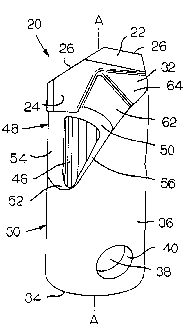
Referring to the drawings, in FIGS. 1, 2 and 5 there is shown a first
specific embodiment of the earth penetrating rotary drill bit generally
designated
as 20. Rotary drill bit 20 has a central longitudinal axis A-A a shown in FIG.
1.
CA 02530872 2005-12-28
WO 2005/005769 PCT/US2004/018289
-6-
The rotary drill bit 20 is a roof bit and functions as a drill bit for
drilling earth
strata whereby debris is generated during the drilling operation. As will be
described in more detail hereinafter, the debris is evacuated from the
vicinity of
the drilling operation (i.e., from the vicinity of the drill bit) through
debris (or dust
ports) under the influence of a vacuum. Rotary drill bit 20 includes a hard
carbide
(e.g., cobalt cemented tungsten carbide) cutting insert 22 that presents
opposite
surfaces that comprise a leading surface 24 and a trailing surface 25. The
cutting
insert 22 also presents a cutting edge 26.
Rotary drill bit 20 further includes an elongate steel bit body
generally designated as 30. Bit body 20 has a distal end (or top end) 32 and a
proximate end (bottom end) 34. Bit body 30 further includes a generally
cylindrical side wall 36 that presents a cylindrical exterior surface 37 and
contains
aperture 40 therein. Bit body 30 further defines an interior cavity 38. As is
well
known in the art, a projection on the drill steel registers with the aperture
40 so as
to connect drill steel to the rotary drill bit.
Bit body 30 contains a helical debris port 46 that is elongate (or
helical) in shape. The bit body 30 further contains a helical scallop 48.
Helical
scallop 48 surrounds the helical debris port 46 so as to define the perimeter
of the
helical debris port 46.
The helical scallop 48 shown in rotary drill bit 20 has an orientation
so as to have a pitch that equals about 7.3 inches (18.54 centimeters). The
helical
scallop 48 may have a pitch that ranges between about 3 inches (7.62
centimeters)
and about 15 inches (38.1 centimeters). As an alternative range for the pitch,
the
helical scallop 48 may have a pitch that ranges between about 5 inches (12. 7
centimeters) and about 10 inches (25.4 centimeters). As still another
alternate
range for the pitch, the helical scallop 48 may have a range of the pitch
between
about 6 inches (15.24 centimeters) and about 10 inches (25.4 centimeters). The
orientation of the helical debris port 46 is such so that it has a pitch like
that of the
helical scallop 48.
Helical scallop 48 is defined by contiguous surfaces that comprise a
top (or axial forward) surface 50, a bottom (or axial rearward) surface 52,
and
CA 02530872 2005-12-28
WO 2005/005769 PCT/US2004/018289
-7-
opposite side surfaces 54 and 56. The top surface 50 is generally parallel to
the
major axis of the helical debris port 46. The one side surface 54 is
contiguous
with the top surface 50, but is twisted relative to the top surface 50. The
other side
surface 56 is contiguous with the top surface 50 and has an orientation so as
to be
generally parallel to the top surface 50. The bottom surface 52 is contiguous
with
the side surfaces (54, 56), and is oriented so as to face somewhat inwardly
toward
the cavity 38.
Referring to FIG. 2, it can be seen that the cutting insert 22 and the
helical debris port 46 are axially spaced apart in that the cutting insert 22
is axial
forward of the helical debris port 46. However, the cutting insert 22 and the
helical debris port 46 have a relative vertical orientation so that the
helical debris
port 46 is on either side (i.e., leading side 24 and trailing side 25) of the
cutting
insert 22. In this regard, the trailing surface 25 of the cutting insert 22 is
rotationally ahead of (i.e., offset in a counter-clockwise rotational
direction a
shown in FIG. 2 relative to) the rear edge of the helical debris port 46 that
is
defined by the one side surface 54 of the helical scallop 48. The leading
surface
24 of the cutting insert 22 is rotationally behind of (i.e., offset in a
clockwise
rotational direction as shown in FIG. 2 relative to) the forward edge of the
helical
debris port 46. What this shows is that vertical downward extensions of the
planes
in which the leading side surface 24 and the trailing side surface 25 lie will
intersect the helical debris port 46. One may characterize this relative
positioning
as the cutting insert having a vertical orientation relative to the helical
debris port
so as to be within the vertical extension of the periphery of the helical
debris port.
Bit body 30 contains a transverse slot 60 therein at the top end 32
thereof. The transverse slot 60 receives the cutting insert 22. Cutting insert
22
may be affixed within the slot 60 by brazing or the like. Bit body 30 further
includes a feeder surface 62 and an inclined surface 64. The feeder surface 62
is
adjacent to the inclined surface 64.
In operation, the rotary drill bit 20 is pressed against the earth strata
and is driven so as to rotate about its central longitudinal axis. The cutting
insert
22 is in direct contact against the earth strata so as to drill a borehole. As
a
CA 02530872 2005-12-28
WO 2005/005769 PCT/US2004/018289
-8-
consequence of drilling the borehole, there is generated a volume of debris in
the
form of fine particles (i.e., dust) and larger particles. The debris is
generated at,
and hence initially located in, the vicinity of the cutting insert and the
upper region
of the rotary drill bit.
A vacuum is at the helical debris port 46. Under the influence of
the vacuum, the debris moves over the feeder surface 62 and along the helical
scallop 48 into the corresponding helical debris port 46. The helical
orientation of
the debris port 46 and the helical scallop 48 facilitate the efficient and
relatively
quick evacuation of the debris from the vicinity of the rotary drill bit 20.
The
efficient and relatively quick evacuation of the debris from the vicinity of
the
rotary drill bit 20 provides for the advantages of higher drilling rates along
with
smoother drilling and cooler drilling.
Referring to FIGS. 3 and 4, in FIG. 3 there is shown a cold-formed
steel bit body blank 30A used to make a rotary drill bit like that of rotary
drill bit
20. The cold-formed bit body blank 30A contains a plug 44 that is in the
general
shape of a cutting insert. The bit body blank 30A also presents a formed
protrusion 42 in the sidewall thereof.
As shown in FIG. 4, to finish the bit body blank 30A, the plug 44 is
machined out (i.e., material is removed) to form a slot 60 and the bit body
blank is
2o drilled out (i.e., material is removed) in the area of the formed
protrusion 42 to
form the helical debris port 46.
Thus, it can be seen that the bit body 30 is made according to the
following steps. First, there is the step of providing a cold-formed bit body
blank
that has a helical scallop, a plug in the location where there will be the
cutting
insert, and a formed protrusion within the helical scallop and at the location
where
there will be a helical debris port. Second, there is the step of machining
out the
plug (i.e., removing material) to form a slot that receives the cutting
insert. Third,
there is the step of drilling out the bit body in the location of the formed
protrusion
(i.e., removing material) so as to form the helical debris port.
It should also be appreciated that while the bit body is described as
being cold-formed, applicant contemplates that the bit body could be cast.
CA 02530872 2011-04-29
68188-229
-9-
Referring to FIGS. 6 and 7, there is shown another embodiment of
a rotary drill bit generally designated as 70. Rotary drill bit 70 includes a
hard
carbide (e.g., cobalt cemented tungsten carbide) cutting insert 72. Cutting
insert
72 has a trio of lobes 74, 76, 78 wherein each one of the lobes 74, 76, 78
presents
a cutting edge 73, 75 77, respectively, on the top surface 80 of the cutting
insert
72. Cutting insert 72 has a bottom surface 82 wherein a lobed projection 84
extends from the bottom surface 82. The cutting insert 72 has a trio of
arcuate
side surfaces 86. Cutting insert 72 has a structure along the lines of at
least one of
the cutting inserts disclosed and described in pending United States Patent
No. 6,595,305 to Dunn et at. for a DRILL BIT, HARD MEMBER AND BIT BODY.
Rotary drill bit 70 has an elongate bit body 90. Bit body 90 has an
opposite top end (or distal end) 92 and bottom end (or proximate end) 94. Bit
body 90 has a sidewall 96 that presents a generally cylindrical exterior
surface 97
and contains an aperture 98. As mentioned in connection with the description
of
the connection between the rotary drill bit 20 and the drill steel, a
projection on the
drill steel registers with the aperture 98 so as to connect the rotary drill
bit 70 to
the drill steel. Bit body 90 defines an interior cavity 100. The bit body 90
contains at the top end 92 thereof a lobed socket 102.
Bit body 90 contains a helical debris port 108. Bit body 90 further
includes a helical scalloped portion 110 that extends from the top end 92 in
an
axial rearward direction down along the exterior surface 97 of the bit body
90.
The helical debris port 108 is located near, but axial forward of, the
termination of
the helical scalloped portion 110.
The helical scallop 110 has an orientation so as to have a pitch that
equals about 3 inches (7.62 centimeters). The helical scallop 110 may have a
pitch
that ranges between about 3 inches (7.62 centimeters) and about 15 inches
(38.1
centimeters). As an alternative range for the pitch, the helical scallop 110
may
have a pitch that ranges between about 5 inches (12. 7 centimeters) and about
10
inches (25.4 centimeters). As still another alternate range for the pitch, the
helical
CA 02530872 2005-12-28
WO 2005/005769 PCT/US2004/018289
-10-
scallop 110 may have a range of the pitch between about 6 inches (15.24
centimeters) and about 10 inches (25.4 centimeters). The orientation of the
helical
debris port 108 is such so that it has a pitch like that of the helical
scallop 110.
In operation, the rotary drill bit 70 is pressed against the earth strata
and is driven so as to rotate about its central longitudinal axis. The cutting
insert
72 is in direct contact against the earth strata so as to drill a borehole. As
a
consequence of drilling the borehole, there is generated a volume of debris in
the
form of fine particles (i.e., dust) and larger particles. The debris is
generated at
and hence initially located in the vicinity of the cutting insert and the
upper region
of the rotary drill bit.
A vacuum is at the helical debris ports 108. Under the influence of
the vacuum, the debris moves over the surface of the scalloped portion 110
into
the corresponding debris port 108. The helical orientation of the debris port
108
and the helical scallop 110 facilitate the efficient and relatively quick
evacuation
of the debris from the vicinity of the rotary drill bit 70. The efficient and
relatively
quick evacuation of the debris from the vicinity of the rotary drill bit 70
provides
for the advantages of higher drilling rates along with smoother drilling and
cooler
drilling.
Referring to FIGS. 8 through 10, there is shown still another
specific embodiment of a rotary drill bit generally designated as 120. Rotary
drill
bit 120 includes a hard carbide (e.g., cobalt cemented tungsten carbide)
cutting
insert 122. Cutting insert 122 includes a top surface 124 that presents
cutting
edges 126. Cutting insert 122 also has a bottom surface 128 that has
positioning
projections 130 and spacer bumps 132 extending therefrom. Cutting insert 122
has a transverse surface 134 and a peripheral side surface 136.
Rotary drill bit 120 further includes an elongate bit body 138 that has
a top end (distal end) 140 and a bottom end (proximate end) 142. There are a
pair
of holes 141 in the top end 140 of the bit body 138. Bit body 138 further
includes a
sidewall 144 that presents an exterior surface 145. Bit body 138 defines an
interior
cavity 146 and contains an aperture 148. A projection on a drill steel
registers with
the aperture 140 so as to connect the rotary drill bit 120 to the drill steel.
CA 02530872 2005-12-28
WO 2005/005769 PCT/US2004/018289
-11-
Bit body 138 further contains a helical debris port 154 and a helical
scallop 156. The helical scallop 156 has an orientation may have a pitch that
ranges between about 3 inches (7.62 centimeters) and about 15 inches (38.1
centimeters). As an alternative range for the pitch, the helical scallop 156
may
have a pitch that ranges between about 5 inches (12. 7 centimeters) and about
10
inches (25.4 centimeters). As still another alternate range for the pitch, the
helical
scallop 156 may have a range of the pitch between about 6 inches (15.24
centimeters) and about 10 inches (25.4 centimeters). The orientation of the
helical
debris port 154 is such so that it has a pitch like that of the helical
scallop 156.
There is a braze joint 160 between the cutting insert 122 and the
top end 140 of the bit body 138. The holes 141 in the top end 140 of the bit
body
138 receive the positioning projections 130 so as to help position the cutting
insert
122 relative to the bit body 138. The spacer bumps 132 help maintain a pre-
selected uniform thickness of the braze joint 160 between the cutting insert
122
and the top end 140 of the bit body 138.
In operation, the rotary drill bit 120 is pressed against the earth
strata and is driven so as to rotate about its central longitudinal axis. The
cutting
insert 122 is in direct contact against the earth strata so as to drill a
borehole. As a
consequence of drilling the borehole, there is generated a volume of debris in
the
form of fine particles (i.e., dust) and larger particles. The debris is
generated at
and hence initially located in the vicinity of the cutting insert and the
upper region
of the rotary drill bit.
A vacuum is at the helical debris ports 154. Under the influence of
the vacuum, the debris moves over the scallop surfaces 156 into the
corresponding
debris port 154. The helical orientation of the debris ports 154 and the
helical
scallops 156 facilitate the efficient and relatively quick evacuation of the
debris
from the vicinity of the rotary drill bit 120. The efficient and relatively
quick
evacuation of the debris from the vicinity of the rotary drill bit 120
provides for
the advantages of higher drilling rates along with smoother drilling and
cooler
drilling.
CA 02530872 2005-12-28
WO 2005/005769 PCT/US2004/018289
-12-
It can thus be appreciated that the rotary drill bits disclosed and
described herein provide certain improvements and advantages. These drill bits
provide for the efficient and improved evacuation of debris from the vicinity
of the
rotary drill bit during the drilling operation. These rotary drill bits that
provide for
better evacuation of debris enhance the ability of the rotary drill bit to
operate at a
higher speed and provide for smoother and cooler operation.
One can appreciate that the present invention includes a method of
making a rotary drill bit body comprising the steps of providing a rotary
drill bit
body blank wherein the rotary drill bit body blank is either cast or cold-
formed,
and the rotary drill bit body blank having a helical scallop, and the rotary
drill bit
body blank further having a distal end containing a plug and a formed
protrusion
within the helical scallop; removing the plug so as to form a slot for
receiving a
cutting insert; and removing the formed protrusion so as to form a helical
debris
port.
One can also appreciate that the present invention provides for a
method making a rotary dill bit. This method comprises the steps of. providing
a
drill bit body having a side wall and opposite ends, the drill bit body
containing a
helical debris port in the side wall thereof, and the drill bit body
containing a
helical scallop surrounding the debris port; providing a cutting insert; and
affixing
the cutting insert to the drill bit body at a distal one of the opposite ends
thereof so
that the helical scallop is proximate to the cutting insert so that debris
from the
drilling operation impinges upon the helical scallop whereby the helical
scallop
directs the debris into the helical debris port.
The patents and other documents identified herein are hereby
incorporated by reference herein.
Other embodiments of the invention will be apparent to those
skilled in the art from a consideration of the specification (including the
drawings)
or practice of the invention disclosed herein. It is intended that the
specification
and examples be considered as illustrative only, with the true scope and
spirit of
the invention being indicated by the following claims.