Note: Descriptions are shown in the official language in which they were submitted.
CA 02530984 2005-12-29
WO 2005/003547 PCT/US2004/021677
APPARATUS FOR GENERATING POWER AND HYBRID FUEL
VAPORIZATION SYSTEM THEREFOR
[0001] The present invention relates to a power producing
apparatus and fuel vaporization system therefor.
[0002] The need to power portable electronics equipment,
communications gear, medical devices and other equipment in remote
field service has been on the rise in recent years, increasing the demand
for highly efficient, mobile power systems. These applications require
power sources that provide both high power and energy density, while also
requiring minimal size and weight, low emissions and cost.
[0003] To date-; batteries have been the principal means for
supplying portable sources of power. However, due to their size and
weight, as well as the time required for recharging, batteries have proven
inconvenient for continuous use applications. Moreover, portable batteries
are generally limited to power production in the range of several milliwatts
to a few watts and thus cannot address the need for significant levels of
mobile, lightweight power production.
[0004] Small generators powered by internal combustion engines,
whether gasoline- or diesel-fueled have also been used. However, the
noise and emission characteristics of such generators have made them
wholly unsuitable for a wide range of mobile power systems and unsafe for
indoor use. While conventional heat engines powered by high energy
density liquid fuels offer advantages with respect to size, thermodynamic
scaling and cost considerations have tended to favor their use in larger
power plants.
[0005] In view of these factors, a void exists with regard to power
systems in the size range of approximately 5.1 to 51 kg-mlsec (50 to 500
watts). Moreover, in order to take advantage of high energy density liquid
fuels, ~ improved fuel preparation and delivery systems capable of low
CA 02530984 2005-12-29
WO 2005/003547 PCT/US2004/021677
2
fueling rates are needed. Additionally, such systems must also enable
highly efficient combustion with minimal emissions.
[0006] A combustion device wherein fuel is atomized by an
ultrasonic atomizing device is proposed in U.S. Patent No. 5,127,822.
According to this patent, atomizers have been proposed wherein fuel is
supplied to a combustion chamber in fine droplets to accelerate
vaporization of the fuel and reduce the combustor residence time required
to achieve acceptable combustion efficiency.
[0007] U.S. Patent No. 5,127,822 proposes an arrangement
wherein fuel is supplied at 5 cc/min and the fuel is atomized into droplets
having a Sauter Mean Diameter (SMD) of 40 pm. Other atomizing
techniques are proposed in U.S. Patent Nos. 6,095,436 and 6,102,687.
An ultrasonic atomizer for supplying fuel to an internal combustion engine
is proposed in U.S. Patent No. 4,986,248.
(0008] U.S. Patent No. 4,013,396 proposes a fuel aerosolization
apparatus wherein a hydrocarbon fuel (e.g., gasoline, fuel oil, kerosene,
etc.) is dispensed into a condensation area with the intention of forming an
aerosolized fuel of relatively even sized droplets less than 1 pm in
diameter.
(0009] A fuel-vaporizing device said to address problems
associated with incomplete combustion of fuel aerosols in internal
combustion engines is proposed in U.S. Patent No. 5,472,645. According
to U.S. Patent No. 5,472,645, because aerosol fuel droplets do not ignite
and combust completely in internal combustion engines, unburned fuel
residues are exhausted from the engine as pollutants such as
hydrocarbons (HC), carbon monoxide (CO) and aldehydes with
concomitant production of oxides of nitrogen (NOx). The proposal of U.S.
Patent No. 5,472,645 is intended to improve combustion of aerosol fuels
by breaking liquid fuel down into an air-fluid stream of vaporized or gas-
phase elements containing some unvaporized aerosols containing
hydrocarbons of higher molecular weight, the lighter fuel distillates said to
quickly evaporate to the gas phase, mix with air and are to be fed to an
CA 02530984 2005-12-29
WO 2005/003547 PCT/US2004/021677
3
internal combustion engine while the heavier fuel portions are said to be
transformed into a gas-phase vaporized state before they exit a cyclone
vortex device and enter the intake manifold of the engine.
[0010] U.S. Patent No. 4,344,404 proposes an apparatus for
supplying aerosol fuel droplets mixed with air to an internal combustion
engine or burner, the fuel droplets said to have sizes of 0.5 to 1.5 pm. The
liquid fuel in aerosol form is intended to be mixed with air in a air-to-fuel
ratio of about 18:1 to produce the least CO, HC and NOX emissions from
the engine.
[0011] Various devices have been proposed for heating fuels into a
vaporized fuel that is combusted by a burner. See, for example, U.S.
Patent Nos. 4,193,755; 4,320,180; and 4,784,599.
[0012] U.S. Patent No. 3,716,416 discloses a fuel-metering device
intended for use in a fuel cell system. The fuel cell system is intended to
be self-regulating, producing power at a predetermined level. The
proposed fuel metering system includes a capillary flow control device for
throttling the fuel flow in response to the power output of the fuel cell,
rather thaw to provide improved fuel preparation for subsequent
combustion. Instead, the fuel is intended to be fed to a fuel reformer for
conversion to H2 and then fed to a fuel cell. In a preferred embodiment,
the capillary tubes are made of metal and the capillary itself is used as a
resistor, which is in electrical contact with the power output of the fuel
cell.
Because the flow resistance of a vapor is greater than that of a liquid, the
flow is throttled as the power output increases. The fuels suggested for
use include any fluid that is easily transformed from a liquid to a vapor
phase by applying heat and flows freely through a capillary. Vaporization
appears to be achieved in the manner that vapor lock occurs in automotive
engines.
[0013] U.S. Patent No. 6,276,347 proposes a supercritical or near-
supercritical atomizer and method for achieving atomization or
vaporization of a liquid. The supercritical atomizer of U.S. Patent No.
6,276,347 is said to enable the use of heavy fuels to fire small, light
CA 02530984 2005-12-29
WO 2005/003547 PCT/US2004/021677
4
weight, low compression ratio, spark-ignition piston engines that typically
burn gasoline. The atomizer is intended to create a spray of fine droplets
from liquid, or liquid-like fuels, by moving the fuels toward their
supercritical temperature and releasing the fuels into a region of lower
pressure on the gas stability field in the phase diagram associated with the
fuels, causing a fine atomization or vaporization of the fuel. Utility is
disclosed for applications such as combustion engines, scientific
equipment, chemical processing, waste disposal control, cleaning, etching,
insect control, surface modification, humidification and vaporization.
[0014] To minimize decomposition, U.S. Patent Nos. 6,276,347 and
6,390,076 each propose keeping the fuel below the supercritical
temperature until passing the distal end of a restrictor for atomization. For
certain applications, heating just the tip of the restrictor is desired to
minimize the potential for chemical reactions or precipitations. This is said
to .reduce problems associated with impurities, reactants or materials in
the fuel stream which otherwise tend to be driven out of solution, clogging
lines and filters. Working at or near supercritical pressure suggests that
the fuel supply system operate in the range of 21.1 to 56.2 kglcm2 (300 to
800 psig). While the use of supercritical pressures and temperatures
might reduce clogging of the atomizer, it appears to require the use of a
relatively more expensive fuel pump, as well as fuel lines, fittings and the
like that are capable of operating at these elevated pressures.
[0015] Power conversion arrangements are proposed in U.S. Patent
Nos. 4,638,172; 5,836,150; 5,874,798; 5,932,940; 6,109,222; and
6,198,038. Of these, U.S. Patent No. 4,638,172 proposes a direct current
generator operatively coupled to a small internal combustion engine, the
generator said to output between 4 volts (V) and 150 milliamperes (mA) to
110 V and over 250 mA. U.S. Patent No. 5,836,150 proposes a micro
thrust and heat generator that can be used as a thrust source for a micro
machined turbo-electric generator. U.S. Patent No. 5,874,798 proposes a
micro-turbine generator device wherein air is fed into the device to
generate electricity for use with portable electronic products. U.S. Patent
CA 02530984 2005-12-29
WO 2005/003547 PCT/US2004/021677
No. 5,932,940 proposes a micro-gas turbine engine including a
combustion chamber, used to drive a microgenerator which is intended to
output 11.0 to 3.1 kg-m/sec (10 to 30 watts) of electrical power for
replacement of batteries in portable electronic devices while producing 20
times the power for the same weight and volume (e.g., replacing batteries
for portable computers, radios, telephones, power tools, heaters, coolers,
military applications, etc.). U.S. Patent No. 6,109,222 patent proposes a
micro heat engine that is intended to generate 1.0 to 3.1 kg-m/sec (10 to
30 watts) of electrical power wherein a free piston is reciprocated by a
periodic combustion process.
[0016] The present invention provides a hybrid fuel vaporizing
system for use in an apparatus for producing power from a source of liquid
fuel. The hybrid fuel vaporizing system for use in an apparatus for
combusting fuel from a source of liquid fuel, comprises:
(a) at least one capillary flow passage, said at least one
capillary flow passage having an inlet end and an outlet end, said inlet end
in fluid 'communication with the source of liquid fuel;
(b) a heat source arranged along said at least one
capillary flow passage, said heat source operable to heafi the liquid fuel in
said at least one capillary flow passage to a level sufficient to change at
least a portion thereof from a liquid state to a vapor state; and
(c) a vaporizing member having a first surface and a
second surface, said first surface exposed to heat produced by the
apparatus for combusting fuel, said vaporizing member positioned so that
fuel exiting said outlet end of said at least one capillary flow passage
impinges on said second surface
whereby a stream of substantially vaporized fuel is delivered
for combustion.
[0017] The present invention also provides an apparatus for
producing power from a source of liquid fuel. The apparatus for producing
power from a source of liquid fuel, comprises:
CA 02530984 2005-12-29
WO 2005/003547 PCT/US2004/021677
6
(a) at least one capillary flow passage, said at least one
capillary flow passage having an inlet end and an outlet end, said inlet end
in fluid communication with the source of liquid fuel;
(b) a heat source arranged along said 'at least one
capillary flow passage, said heat source operable to heat the liquid fuel in
said at least one capillary flow passage to a level sufficient to change at
least a portion thereof from a liquid state to a vapor state;
(c) a vaporizing member having a first surface and a
second surface, said first surface exposed to heat produced by
combusting fuel, said vaporizing member positioned so that fuel exiting
said outlet end of said at least one capillary flow passage impinges on said
second surface to produce a stream of substantially vaporized fuel;
(d) a combustion chamber for combusting the stream of
substantially vaporized fuel and air, said combustion chamber in
communication with said first surface of said vaporizing member; and
(e) a conversion device operable to convert heat released
by combustion in said combustion chamber into mechanical and/or
electrical power.
[0018] Also provided is a method of generating power. The method
of generating power, comprises;
(a) supplying liquid fuel to at least one capillary flow
passage, the at least one capillary flow passage positioned so that fuel
exiting the at least one capillary flow passage impinges on a vaporizing
member having a first surface and a second surface;
(b) heating the fuel that impinges on the vaporizing
member and causing a stream of substantially vaporized fuel to be formed;
(c) combusting the vaporized fuel in a combustion
chamber; and
(d) converting heat produced by combustion of the
vaporized fuel in the combustion chamber into mechanical and/or electrical
power using a conversion device,
CA 02530984 2005-12-29
WO 2005/003547 PCT/US2004/021677
7
wherein the first surface of the vaporizing member is
positioned proximate to the combustion chamber so that heat produced
from combustion is effective to heat the fuel that impinges on the second
surface of the vaporizing member and supply the stream of substantially
vaporized fuel for combustion.
[0019] In one aspect, a power generator having a fuel preparation
system with the ability to form small fuel droplets and/or vapor, operate at
low fuel supply pressures, have low parasitic power loss characteristics
and provide for the control of fouling, clogging and gumming, is provided.
[0020] In another aspect, the capillary flow passage can include a
capillary tube and the heat source can include a resistance-heating
element, a section of the tube heated by passing electrical current
therethrough.
[0021] Further, in another aspect, the conversion device includes a
micro-turbine, a micro-turbine with electrical generator, an external
combustion engine, such as a Stirling engine, an external combustion
engine, such as a Stirling engine, with electrical generator, a
thermoelectric device or a thermophotovoltaic device.
[0022] In another aspect, a heat exchanger is provided which
includes an exhaust duct through which exhaust gases removed from the
combustion chamber are circulated and an air passage through which air
is circulated, the heat exchanger preheating the air in the air passage by
transferring heat from the exhaust gases in the exhaust duct to the air.
This aspect can also include an air blower, the air blower supplying air
under pressure to the combustion chamber such that the pressurized air
mixes with the vaporized fuel in a desired air-fuel ratio suitable for
combustion of the air-fuel mixture.
[0023] To address problems associated with the formation of
deposits during the heating of liquid fuel, another aspect provides means
for cleaning deposits formed during operation.
CA 02530984 2005-12-29
WO 2005/003547 PCT/US2004/021677
8
[0024] The invention will now be described in more detail with
reference to preferred forms of the invention, given only by way of
example, and with reference to the accompanying drawings, in which:
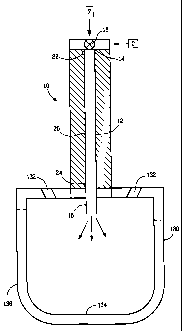
[0025] FIG. 1 presents a hybrid fuel-vaporizing device, in partial
cross section, which includes a capillary flow passage and a vaporizing
chamber in accordance with an embodiment of the invention;
[0026] FIG. 2 shows a hybrid fuel-vaporizing device having a multi-
capillary arrangement and a vaporizing chamber that can be used to
implement the device and system of FIG. 4;
[0027] FIG. 3 shows a sectional view of the device shown in FIG. 2,
taken along line 3--3;
[0028] FIG. 4 shows details of a device that can be used to vaporize
fuel and oxidize deposits in a hybrid fuel-vaporizing device having a multi-
capillary arrangement and a vaporizing chamber to deliver substantially
vaporized fuel for use in the practice of the present invention;
[0029] FIG. 5 shows a schematic of a control device to deliver fuel
and optionally oxidizing gas to a hybrid fuel-vaporizing device having a
capillary flow passage and a vaporizing chamber;
[0030] FIG. 6 is a schematic view of an apparatus for generating
power in accordance with the invention wherein an external combustion
engine, such as a Stirling engine, is used to generate electricity in
accordance with one embodiment of the invention;
[0031] FIG. 7 shows a partial cross-sectional schematic view of a
power-producing device in accordance with another embodiment of the
invention; .
[0032] FIG. 8 shows a partial cross-sectional schematic view of yet
another power-producing device in accordance with another embodiment
of the invention;
[0033] FIG. 9 is a droplet distribution graph showing percentage of
droplets as a function of droplet diameter demonstrating the benefits of the
fuel vaporizing devices employing capillary flow passages; and
CA 02530984 2005-12-29
WO 2005/003547 PCT/US2004/021677
9
(0034] FIG. 10 compares results of cyclic clogging/de-clogging tests
demonstrating the benefit to long-term operability of a hybrid fuel
vaporization system.
[0035] Reference is now made to the embodiments illustrated in
FIGS. 1-10 wherein like numerals are used to designate like parts
throughout.
[0036] The present invention provides a power producing apparatus
and fuel system therefor which advantageously combusts a high energy
density liquid fuel. The apparatus includes at least one capillary sized flow
passage connected to a fuel supply, a heat source arranged along the flow
passage to heat liquid fuel in the flow passage sufficiently to deliver a
stream of vaporized fuel from the outlet of the capillary flow passage, a
fuel vaporizing chamber in fluid communication with the outlet of the fuel
passage to supply and vaporize liquid fuel for combustion, a combustion
chamber in which the vaporized fuel is combusted, and a conversion
device which converts heat produced by combustion in the combustion
chamber into mechanical and/or electrical power.
[0037] Advantageously, the capillary flow passage may be heated
initially at start up to vaporize the fuel and the vaporized fuel may
subsequently be combusted to produce a flame. The vaporizing chamber
is preferably located in the region of the flame so as to provide rapid
heating and to cause any liquid fuel that enters it to be vaporized. Shortly
after start up, the electrical power to the capillary flow passage may be
gradually reduced such that the fuel supplied to the conventional vaporizer
is a substantially preheated liquid. The fuel exits the vaporizing chamber
and enters the combustion air stream through orifice holes, located and
configured to promote good fuel and air mixing for combustion. The fuel
flow rate through the hybrid capillary fuel vaporization system may be
controlled through the use of a variable speed, constant displacement
pump or, alternatively, the electrical power supplied to the capillary flow
passage may be modulated and controlled to vary its pressure drop/flow
CA 02530984 2005-12-29
WO 2005/003547 PCT/US2004/021677
characteristics, as necessary. For a fixed fuel supply pressure, applying
heat to the capillary flow passage causes a reduction in fuel flow rate while
simultaneously assisting with fuel vaporization.
[0038] It has been observed in the operation of continuously heated
capillary flow passages employing electrical heating that fuel flow rate
versus pressure drop performance degrades as carbon deposits form and
occlude the capillary flow passage. Additionally, electrical power must be
constantly supplied to the capillary, limiting the overall efficiency of the
apparatus.
[0039] During start-up, the electrically heated capillary flow passage
is used to provide fuel vapor for ignition. The capillary flow passage
injects vaporized fuel directly into the vaporizing chamber. Owing to its
preferred proximity to the combustion chamber, the temperature of the
vaporizing chamber elevates, enabling the electric power supplied to the
capillary passage to be reduced and eventually even eliminated. Liquid
fuel then flows directly into the vaporizing chamber, which by this time is
sufficiently hot enough to function. During steady state operation, the high
liquid flow rate through the capillary helps to keep the liquid temperatures
low to minimize clogging. The high liquid flow rate through the capillary
also serves as a solvent to remove deposits formed during start up. Both
these effects help prevent the capillary from clogging. As is preferred, the
flow orifices of the vaporizing chamber are much larger relative to the
capillary flow passage and thus are less vulnerable to clogging.
[0040] During steady state operation, the thermal energy required
for vaporization is obtained from the combustion system directly. When
employed in stand-alone power systems, extracting thermal energy
directly from the combustion system is much more efficient than
generating electricity to power a resistance heater.
[0041] The fuel flow rate through the hybrid fuel vaporizer may be
controlled by several means. The fuel supply pressure may be regulated
so as to vary flow as desired and/or in automatic response to variations in
system pressure losses that result from variations in the fuel vaporization
CA 02530984 2005-12-29
WO 2005/003547 PCT/US2004/021677
11
rate and location of fuel vaporization within the hybrid fuel vaporizer. The
electrical power supplied to the resistance-heated capillary may also be
varied to regulate flow in recognition that the pressure loss characteristics
of the capillary flow passage may be regulated over a broad range by
controlling the liquid preheating/vaporization/vapor superheating process.
Alternatively, the fuel flow rate may be controlled through the use of a
speed regulated, positive displacement pump.
[0042] As indicated, the capillary flow passage can be a capillary
tube heated by a resistance heater, a section of the tube heated by
passing electrical current therethrough. The capillary flow passage also is
characterized by having a low thermal inertia, so that the capillary
passageway can be brought up to the desired temperature for vaporizing
fuel very quickly, e.g., within 2.0 seconds, preferably within 0.5 second,
and more preferably within 0.1 second. The capillary sized fluid passage
is preferably formed in a capillary body such as a single or multilayer
metal, ceramic or glass body. The passage has an enclosed volume
opening to an inlet and an outlet. The heater can be formed by a portion
of the body such as a section of a stainless steel tube or the heater can be
a discrete layer or wire of resistance heating material incorporated in or on
the capillary body.
[0043] The fluid passage may be any shape comprising an
enclosed volume opening to an inlet and an outlet and through which a
fluid may pass. The fluid passage may have any desired cross-section
with a preferred cross-section being a circle of uniform diameter. Other
capillary fluid passage cross-sections include non-circular shapes such as
triangular, square, rectangular, oval or other shape and the cross section
of the fluid passage need not be uniform. The fluid passage can extend
rectilinearly or non-rectilinearly and may be a single fluid passage or multi-
path fluid passage.
[0044] A capillary-sized flow passage can be provided with a
hydraulic diameter that is preferably less than 2 mm, more preferably less
than 1 mm, and most preferably less than 0.5 mm. The "hydraulic
CA 02530984 2005-12-29
WO 2005/003547 PCT/US2004/021677
12
diameter" is a parameter used in calculating fluid flow characteristics
through a fluid carrying element and is defined as four times the flow area
of the fluid-carrying element divided by the perimeter of the solid boundary
in contact with the fluid (generally referred to as the "wetted" perimeter).
For a tube having a circular flow passage the hydraulic diameter and the
actual diameter are equivalent. In the case where the capillary passage is
defined by a metal capillary tube, the tube can have an inner diameter of
0.01 to 3 mm, preferably 0.1 to 1 mm, most preferably 0.15 to 0.5 mm.
Alternatively, the capillary passage can be defined by transverse cross
sectional area of the passage that can be 8 x 10⁻⁵ to 7 mm2, preferably 8 x
10-3 to 8 x 10-' mm2 and more preferably 2 x 10⁻³ to 2 x 10-~ mm2. Many
combinations of a single or multiple capillaries, various pressures, various
capillary lengths, amounts of heat applied to the capillary, and different
shapes and/or cross-sectional areas will suit a given application.
[0045] The conversion device can be an external combustion .
engine, such as a Stirling engine, micro-turbine/generator or other suitable
device for converting heat to mechanical or electrical power with an
optional generator capable of producing up to about 510 kg-m/sec (5,000
watts) of power. The liquid fuel can be any type of hydrocarbon fuel such
as jet fuel, gasoline, kerosene or diesel oil, an oxygenate such as ethanol,
methanol, methyl tertiary butyl ether, or blends of any of these and the fuel
is preferably supplied to the flow passage at pressures of preferably less
than 7.0 kg-m/sec (100 psig), more preferably less than 3.5 kg-m/sec (50
psig), even more preferably less than 0.7 kg-m/sec (10 psig), and most
preferably less than 0.4 kg-m/sec (5 psig). The vaporized fuel can be mixed
with air to form an aerosol having a mean droplet size of 25 pm or less,
preferably 10 pm or less, thus allowing clean and efficient ignition
capabilities.
[0046] According to one preferred form, the vaporized fuel can be
mixed with air at ambient temperature, which is drawn into air supply
passages leading into the combustion chamber. Alternatively, the
vaporized fuel can be mixed with air that has been preheated such as by a
CA 02530984 2005-12-29
WO 2005/003547 PCT/US2004/021677
13
heat exchanger that preheats the air with heat of exhaust gases removed
from the combustion chamber. If desired, the air can be pressurized such
as by a blower prior to mixing with the vaporized fuel.
(0047] As indicated, during vaporization of liquid fuel in a heated
capillary passage, deposits of carbon and/or heavy hydrocarbons may
accumulate on the capillary walls and flow of the fuel can be severely
restricted which ultimately can lead to clogging of the capillary, flow
passage. The rate at which these deposits accumulate is a function of
capillary wall temperature, the fuel flow rate and the fuel type. While fuel
additives may be useful in reducing such deposits, should clogging
develop, the hybrid fuel-vaporizing device may optionally provide means
for cleaning deposits formed during operation.
[0048] The heated capillary flow passage of the hybrid fuel
vaporization system has the ability to form an aerosol of small fuel droplets
(e.g., 25 pm or less, preferably 10 pm or less) when the vaporized fuel
mixes with air at ambient temperature, operating at liquid fuel pressures
below 7.0 kg-m/sec (100 psig), preferably less than 3.5 kg-m/sec (50 psig),
more preferably less than 0.7 kg-m/sec (10 psig), and even more preferably
less than 0.4 kg-m/sec (5 psig). The hybrid fuel vaporization system
possesses the ability to combust fuel at low air supply pressure (e.g.,
below 50.80 mm H20 (2 in H20)), starts rapidly, provides for control of
fouling, clogging and gumming, operates at reduced levels of exhaust
emissions and requires low ignition energy to ignite the fuel-air mixture.
[0049] One advantage provided by the hybrid fuel vaporization
system of the apparatus for generating power is in its ignition energy
requirement characteristics. Minimum ignition energy is a term used to
describe the ease with which an atomized fuel/air mixture can be ignited,
typically with an igniter such as a spark ignition source. The device
according to the invention can provide vaporized fuel and/or aerosol with
droplets having a Sauter Mean Diameter (SMD) of less than 25 pm,
preferably less than 10 pm and more preferably less than 5 pm, such fine
aerosols being useful to improve the start-up characteristics and flame
CA 02530984 2005-12-29
WO 2005/003547 PCT/US2004/021677
14
stability in gas turbine applications. Additionally, very significant
reductions in minimum ignition energy can be achieved for fuels having
values of SMD at or below 25 pm. For example, as discussed in Lefebvre,
Gas Turbine Combustion (Hemisphere Publishing Corporation, 1983) at
page 252, Em;n, a term that correlates the ease with which an atomized
fuel/air mixture may be ignited, is shown to sharply decrease as SMD
decreases. Minimum ignition energy is roughly proportional to the cube of
the Sauter Mean Diameter (SMD) of the fuel droplets in the aerosol. SMD
is the diameter of a droplet whose surface-to-volume ratio is equal to that
of the entire spray and relates to the mass transfer characteristics of the
spray. The relationship between Emin and SMD for various fuels is shown
in Lefebvre to be roughly approximated by the following relationship:
log Em;" = 4.5(log SMD) + k; where Emin is measured in mJoules,
SMD is measured in pm, and
k is a constant related to fuel type.
[0050] According to Lefebvre, heavy fuel oil has a minimum ignition
energy of about 800 mJ at a SMD of 115 pm and a minimum ignition
energy of about 23 mJ at a SMD of 50 pm. Isooctane has a minimum
ignition energy of about 9 mJ at a SMD of 90 pm and a minimum ignition
energy of about 0.4 mJ at a SMD of 40 pm. For a diesel fuel, when SMD
is equal to 100 pm, Emin is about 100 mJ. A reduction in SMD to 30 pm
would yield a reduction in Emin to about 0.8 mJ. As may be appreciated,
ignition system requirements are substantially reduced for SMD values
below 25 pm.
[0051] The power conversion apparatus according to the present
invention has been found to exhibit highly desirable low ignition energy
requirements. A low ignition energy requirement improves the power
producing benefits of the present invention by reducing the weight of the
overall system and maximizing the power output through the reduction of
the parasitic power losses associated with the ignition system.
CA 02530984 2005-12-29
WO 2005/003547 PCT/US2004/021677
[0052] In view of the benefits hereinabove described, low energy
spark ignition devices are preferred for the igniter of the power producing
apparatus. Preferred are small piezo-electric ignition devices capable of
providing a spark energy in the range of about 5 to 7 millijoules (mJ).
Such devices are known to be simple, compact and present no parasitic
load issues. The ultra-fine fuel vaporization provided by the hybrid fuel
vaporization system cooperates to provide excellent ignition characteristics
with low energy piezo-electric ignition devices.
[0053] The emissions characteristics of liquid-fueled combustion
devices are known to be sensitive to the quality of the fuel droplet size
distribution. High quality, fine sprays promote fuel evaporation and
enhance mixing, thereby reducing the need for fuel-rich combustion and
the often-attendant generation of smoke and soot. Small droplets follow
flow streamlines and are less prone to impact against burner walls.
Conversely, large -droplets can impact burner walls and cause increased
CO and hydrocarbon emissions and carbon deposits. This problem is
more noticeable in devices where the flames are highly confined.
[0054] The heat produced during combustion of the vaporized fuel
can be converted to electrical or mechanical power. For instance, the heat
could be converted to any desired amount of electrical or mechanical
power, e.g., up to 510 kg-m/sec (5000 watts) of electrical power or
mechanical power. Compared to portable battery technology which can
only provide approximately 2.0 kg-m/sec (20 W) for a few hours or a noisy,
high emissions, internal combustion engine/generator producing above
102 kg-m/sec (1 kW), the apparatus according to one preferred
embodiment of the invention offers a quiet, clean power source in the few
hundred watt range.
[0055] Various technologies exist for conversion of heat produced in
the combustion chamber according to the invention into electrical or
mechanical power. For instance, in the 2.0 to 510 kg-m/sec (20 to 5000
watt) range, at least the following technologies are contemplated: external
combustion engines, such as a Stirling engine, for conversion of heat into
CA 02530984 2005-12-29
WO 2005/003547 PCT/US2004/021677
16
mechanical power which can be used to drive a generator, micro-gas
turbines which can be used to drive a generator, thermoelectric for direct
conversion of heat into electricity, and thermophotovoltaics for direct
conversion of radiant energy into electricity.
[0056] The thermoelectric devices offer advantages in terms of
being quiet and durable, and coupled with external combustion systems,
offer the potential for low emissions and flexibility as to fuel. Various
types
of thermoelectric generators, which can be used as the conversion device,
include those disclosed in U.S. Patent Nos. 5,563,368; 5,793,119;
5,917,144; and 6,172,427.
[0057] The thermophotovoltaic devices offer advantages in terms of
being quiet, providing moderate power density, and coupled with external
combustion systems offer the potential for low emissions and flexibility as
to fuel. Various types of thermophotovoltaic devices, which can be used
as the conversion device, include hose disclosed in U.S. Patent Nos.
5,512,109; 5,753,050; 6,092,912; and 6,204,442. As shown in U.S. Patent
No. 6,204,442, a heat radiating body can be used to absorb heat from
combustion gases and heat radiated from the heat radiating body is
directed to a photocell for conversion to electricity, thus protecting the
photocell from direct exposure to the combustion gases.
[0058] Micro-gas turbines could be desirable in terms of high
specific power. Microturbine devices, which can be used as the conversion
device, include those disclosed in U.S. Patent Nos. 5,836,150; 5,874,798;
and 5,932,940.
[0059] Stirling engines offer advantages with respect to size, quiet
operation, durability, and coupled with external combustion systems offer
the potential for low emissions and flexibility as to fuel. Stirling engines
that can be used as the conversion device will be apparent to those skilled
in the art.
[0060] Referring now to FIG. 1, a hybrid fuel-vaporizing device for
use in a power-generating device is shown. Hybrid fuel vaporizing device
10, includes a capillary flow passage 12, having an inlet end 14 and an
CA 02530984 2005-12-29
WO 2005/003547 PCT/US2004/021677
17
outlet end 16, outlet end 16. A fuel vaporizing member, which may be a
fuel vaporizing chamber 130, as shown, is positioned so that a first surface
136 is exposed to a combustion chamber (not shown), while the fuel
exiting outlet end 16 of capillary flow passage 12, which is in fluid
communication with fuel vaporizing chamber 130, impinges on a second
surface 134. When at or near operating temperature, the heat of
combustion heats fuel vaporizing chamber 130, causing the fuel that
impinges second surface 134 to vaporize.
[0061] Fuel vaporizing chamber 130 has at least one orifice 132 to
supply the vaporized liquid fuel for combustion. Optionally, a control valve
18 may be provided for placing inlet end 14 of capillary flow passage 12 in
fluid communication with a liquid fuel source F and introducing the liquid
fuel in a substantially liquid state into capillary flow passage 12. The
control valve 18 may be operated by a solenoid (not shown). A heat
source 20 is arranged along capillary flow passage 12.
[0062] As is particularly preferred, heat source 20 is provided by
forming capillary flow passage 12 from a tube of electrically resistive
material, a portion of capillary flow passage 12 forming a heater element
when a source of electrical current is connected to the tube at connections
22 and 24 for delivering current therethrough. During apparatus start-up,
or as may be desired, heat source 20 is operable to heat the liquid fuel in
capillary flow passage 12 to a level sufficient to change at least a portion
thereof from the liquid state to a vapor state and deliver a stream of
substantially vaporized fuel from outlet end 16 of capillary flow passage 12
and into vaporizing chamber 130. By substantially vaporized is meant that
at least 50% of the liquid fuel is vaporized; preferably at least 70%, and
more preferably at least 80% of the liquid fuel is vaporized.
[0063] Fuel vaporizing device 10 may optionally include means for
cleaning deposits formed during operation. The means for cleaning
deposits shown in FIG. 1 includes control valve 18, which can be a three-
way valve for alternatively placing capillary flow passage 12 in fluid
communication with either a source of liquid fuel F or a source of oxidizer
CA 02530984 2005-12-29
WO 2005/003547 PCT/US2004/021677
18
C and heat source 20. In operation, heat source 20 is used to heat the
oxidizer C in capillary flow passage 12 to a level sufficient to oxidize
deposits formed during the heating of the liquid fuel F. In one
embodiment, to switch from a fueling mode to a cleaning mode, the
oxidizer control valve 26 is operable to alternate between the introduction
of liquid fuel F and the introduction of oxidizer C into capillary flow
passage
12 and enables the in-situ cleaning of capillary flow passage when the
oxidizer is introduced into the capillary flow passage.
[0064] One technique for oxidizing deposits includes passing air or
steam through the capillary flow passage. As indicated, the capillary flow
passage is preferably heated during the cleaning operation so that the
oxidation process is initiated and nurtured until the deposits are
consumed. To enhance this cleaning operation, a catalytic substance may
be employed, either as a coating on, or as a component of, the capillary
wall to reduce the temperature and/or time required for accomplishing the
cleaning. For continuous operation of the fuel-vaporizing device, more
than one capillary flow passage 12 can be used such that when a clogged
condition is detected, such as by the use of a sensor, fuel flow can be
diverted to another capillary flow passage 12 and oxidant flow C initiated
through the clogged capillary flow passage to be cleaned. As an example,
a valuing arrangement can be provided to selectively supply liquid fuel or
air to each flow passage.
[0065] Alternatively, fuel flow can be diverted from a capillary flow
passage and oxidant flow initiated at preset intervals. Fuel delivery to a
capillary flow passage can be effected by a controller. For example, the
controller can activate fuel delivery for a preset time period and deactivate
fuel delivery after the preset amount of time. The controller may also
effect adjustment of the pressure of the liquid fuel and/or the amount of
heat supplied to the capillary flow passage based on one or more sensed
conditions. The sensed conditions may include inter alias the fuel
pressure, the capillary temperature or the air-fuel ratio. The controller may
also control one or more capillary flow passages to clean deposits.
CA 02530984 2005-12-29
WO 2005/003547 PCT/US2004/021677
19
[0066] The cleaning technique may also be applied to combustion
devices having a plurality of single capillary flow passage hybrid fuel
vaporization devices. The time period between cleanings may either be
fixed based upon experimentally determined clogging characteristics, or a
sensing and control device may be employed to detect clogging and
initiate the cleaning process as required. For example, a control device
could detect the degree of clogging by sensing the fuel supply pressure to
the capillary flow passage of the hybrid fuel vaporization device.
[0067] As indicated, the oxidation cleaning technique may also be
applied to a single hybrid fuel-vaporizing device that is required to operate
continuously. In this case, multiple capillary flow passages are employed.
An exemplary hybrid multiple capillary flow passage fuel-vaporizing device
80 is illustrated in FIGS. 2 and 3. FIG. 2 presents a schematic view of a
hybrid fuel vaporizer 80 employing a multiple capillary tube arrangement,
integrated into a single capillary assembly 94, each capillary tube having
an inlet end and an outlet end. A fuel vaporizing member, which again
may be a fuel vaporizing chamber 230, is positioned so that a first surface
236 is exposed to a combustion chamber (not shown), while the fuel
exiting the outlet end of capillary flow passage, which is in fluid
communication with fuel vaporizing chamber 230, impinges on a second
surface 234. When at or near operating temperature, the heat of
combustion heats fuel vaporizing chamber 230, causing the fuel that
impinges second surface 234 to vaporize.
[0068] Vaporizing chamber 230 has at least one orifice 232 for
delivering a substantially vaporized stream of fuel for combustion.
Consistent with FIG. 2, a plurality of orifices 232 are preferred. FIG. 3
presents an end view taken along line 3-3 of FIG. 2. As shown, the
assembly may include three capillary tubes 82A, 82B, 82C and a positive
electrode 92 which can include a solid stainless steel rod. The tubes and
the rod can be supported in a body 96 of electrically insulating material
and power can be supplied to the rod and capillary tubes via fittings 98.
For example, direct current can be supplied to upstream ends of one or
CA 02530984 2005-12-29
WO 2005/003547 PCT/US2004/021677
more of the capillary tubes and a connection 95 at the downstream ends
thereof can form a return path for the current through rod 92.
[0069] Reference is made now to FIG. 4, wherein a hybrid multiple
capillary tube vaporizing system 80 is shown. The system includes
capillary tubes 82A through 82C, which are each in fluid communication
with vaporizing chamber 230, fuel supply lines 84A through 84C, oxidizer
supply lines 86A through C, control valves 88A through 88C, power input
lines 90A-90C and common ground 91. The system 80 allows cleaning of
one or more capillary tubes while fuel delivery continues with one or more
other capillary tubes. For example, combustion of fuel supplied via
capillary flow passages 82B and 82C can be carried out during cleaning of
capillary flow passage 82A. Cleaning of capillary flow passage 82A can
be accomplished by shutting off the supply of fuel to capillary tube 82A,
supplying air to capillary flow passage 82A with sufficient heating to
oxidize deposits in the capillary flow passage. Thus, the cleaning of one
or several capillaries can be carried out while continuously delivering fuel.
The one or more capillary flow passages being cleaned are preferably
heated during the cleaning process by an electrical resistance heater or
thermal feedback from the application. Again, the time period between
cleanings for any given capillary flow passage may either be fixed based
upon known clogging characteristics, determined experimentally, or a
sensing and control system may be employed to detect deposit buildup
and initiate the cleaning process as required.
[0070] FIG. 5 shows an exemplary schematic of a control system to
operate an apparatus in accordance with the present invention, the
apparatus incorporating an oxidizing gas supply for cleaning clogged
capillary passages. The control system includes a controller 100 operably
connected to a fuel supply 102 that supplies fuel and optionally air to a
flow passage such as a capillary flow passage 104, which is in fluid
communication with vaporizing chamber 330. Vaporizing chamber 330
possesses at least one orifice 332 for the delivery of substantially
vaporized fuel. The controller is also operably connected to a power
CA 02530984 2005-12-29
WO 2005/003547 PCT/US2004/021677
21
supply 106 that delivers power to a resistance heater or directly to a metal
capillary flow passage 104 for heating the tube sufficiently to vaporize the
fuel. If desired, the combustion system can include multiple flow passages
and heaters operably connected to the controller 100. The controller 100
can be operably connected to one or more signal sending devices such as
an on-off switch, thermocouple, fuel flow rate sensor, air flow rate sensor,
power output sensor, battery charge sensor, etc. whereby the controller
100 can be programmed to automatically control operation of the
combustion system in response to the signals) outputted to the controller
by the signal sending devices 108.
[0071] Referring again to FIG. 1, in operation, the hybrid fuel
vaporizing device of the apparatus is positioned within a combustion
chamber so that the heat produced by combustion heats vaporizing
chamber 130 such that, after warm-up and the reduction or discontinuance
of capillary passage heating, the warmed or unheated liquid fuel is heated
sufficiently to substantially vaporize the liquid fuel as it passes through
the
vaporizing chamber orifices 132, reducing or eliminating the need to
electrically heat the capillary flow passage 12.
[0072] As will be appreciated, the fuel vaporizing device and
attendant system depicted in FIGS. 1 through 5 may also be used in
connection with another embodiment of the present invention. Referring
again to FIG. 1, the means for cleaning deposits includes control valve 18,
which may again be a three-way valve, for placing capillary flow passage
12 alternatively in fluid communication with a solvent or a source of liquid
fuel, enabling the in-situ cleaning of capillary flow passage 12 when the
solvent is introduced into capillary flow passage 12. While a wide variety
of solvents have utility, the solvent may comprise liquid fuel from the liquid
fuel source. When this is the case, no control valve may be required, as
there is no need to alternate between fuel and solvent, and the heat
source should be phased-out or deactivated during the cleaning of
capillary flow passage 12.
CA 02530984 2005-12-29
WO 2005/003547 PCT/US2004/021677
22
(0073] FIG. 6 shows a schematic of an apparatus in accordance
with the invention which includes a free-piston Stirling engine 30, a
combustion chamber 34 wherein heat at 550-750°C is converted into
mechanical power by a reciprocating piston which drives an alternator 32
to produce electrical power. The assembly also includes a hybrid fuel
vaporizer 80, a heater assembly 36, a controller 38, a rectifier/regulator 40,
a battery 42, a fuel supply 44, a recuperator 46, a combustion blower 48, a
cooler 50, and a cooler/blower 52. In operation, the controller 38 is
operable to control delivery of fuel to the hybrid fuel vaporizer 80 and to
control combustion of the fuel in the chamber 34 such that the heat of
combustion drives a piston in the Stirling engine such that the engine
outputs electricity from the alternator 32. If desired, the Stirling
engine/alternator can be replaced with a kinematic Stirling engine which
outputs mechanical power. Examples of combustion chambers and air
preheating arrangements can be found in U.S. Patent Nos. 4,277,942,
4,352,269, 4,384,457 and 4,392,350.
(0074] FIG. 7 presents a partial cross-sectional schematic view of a
power-producing device in accordance with another embodiment of the
invention, which can form part of a heat conversion device such as a
Stirling engine assembly. As shown in FIG.7, air delivered to an air inlet
by an air blower enters the combustion chamber 34 and mixes with
vaporized fuel delivered to the chamber by the hybrid fuel vaporizer 80.
Heat of combustion in the chamber 34 heats the end of the Stirling engine
30 and a sliding piston reciprocates within an alternator in a manner that
generates electricity. The chamber 34 can be designed to allow the
exhaust gases to preheat incoming air and thus lower the energy
requirements for combusting the fuel. For instance, the housing can
include a multiwall arrangement, which allows the incoming air to circulate
in a plenum, which is heated by exhaust gases circulating in an exhaust
passage. Inlet air (indicated by arrow 55) can be caused to swirl in the
combustion chamber by passing the air through swirler vanes 56 around
the combustion chamber 34. The combusted air-fuel mixture heats the
CA 02530984 2005-12-29
WO 2005/003547 PCT/US2004/021677
23
heat conversion device (Stirling engine) 30 and exhaust gases (indicated
by arrows 57) are removed from the combustion chamber.
(0075] In FIG. 8, another embodiment of a hybrid fuel vaporizer is
shown as part of a heat conversion device, which may be an external
combustion engine assembly, such as a Stirling engine. The hybrid fuel
vaporizer and heat conversion device is schematically shown in partial
cross-section. Hybrid fuel vaporizing device 400, includes a capillary flow
passage 412, having an inlet end 414 and an outlet end 416, outlet end
416 positioned proximate to fuel-vaporizing member 530. Fuel vaporizing
member 530 is advantageously configured to have a relatively large
surface area to aid in the transfer of the heat of combustion from
combustion chamber 600. As shown, fuel vaporizing member 530 is
positioned so that a first surface 536 is exposed to combustion chamber
600, while the fuel exiting outlet end 416 of capillary flow passage 412
impinges on a second surface 534. When the heat conversion device is at
or near operating temperature, the heat of combustion heats fuel
vaporizing member 530, causing the fuel that impinges second surface
534 to vaporize.
[0076] Fuel vaporizing member 530 has an outer periphery 532,
which when positioned within passage 610, forms a peripheral gap 532.
As may be appreciated, when passage 610 and fuel vaporizing member
530 are both circular in cross-section, peripheral gap 532 will be an
annular gap. Vaporized fuel exiting peripheral gap 532 flows through
passage 610 for subsequent combustion. Optionally, a control valve 418
may be provided for placing inlet end 414 of capillary flow passage 412 in
fluid communication with a liquid fuel source F and introducing the liquid
fuel in a substantially liquid state into capillary flow passage 412. The
control valve 418 may be operated by a solenoid (not shown).
[0077] A heat source 420 is arranged along capillary flow passage
412. As is particularly preferred, heat source 420 is provided by forming
capillary flow passage 412 from a tube of electrically resistive material, a
portion of capillary flow passage 412 forming a heater element when a
CA 02530984 2005-12-29
WO 2005/003547 PCT/US2004/021677
24
source of electrical current is connected to the tube at connections 422
and 424 for delivering current therethrough. During apparatus start-up, or
as may be desired, heat source 420 is operable to heat the liquid fuel in
capillary flow passage 412 to a level sufficient to change at least a portion
thereof from the liquid state to a vapor state and deliver a stream of
substantially vaporized fuel from outlet end 416 of capillary flow passage
412.
[0078] As with the previously described embodiments, fuel
vaporizing device 400 may optionally include means for cleaning deposits
formed during operation. The means for cleaning deposits shown in FIG.
8 includes control valve 418, which can be a three-way valve for
alternatively placing capillary flow passage 412 in fluid communication with
either a source of liquid fuel F or a source of oxidizer C and heat source
420. In operation, heat source 420 is used to heat the oxidizer C in
capillary flow passage 412 to a level sufficient to oxidize deposits formed
during the heating of the liquid fuel F. In one embodiment, to switch from
a fueling mode to a cleaning mode, the oxidizer control valve 418 is
operable to alternate between the introduction of liquid fuel F and the
introduction of oxidizer C into capillary flow passage 12 and enables the
in-situ cleaning of capillary flow passage 412 when the oxidizer is
introduced into the capillary flow passage 412.
[0079] Air or steam may be passed through the capillary flow
passage 412. The capillary flow passage 412 is preferably heated during
the cleaning operation so that the oxidation process is initiated and
nurtured until the deposits are consumed. To enhance this cleaning
operation, a catalytic substance may be employed, either as a coating on,
or as a component of, the capillary wall to reduce the temperature and/or
time required for accomplishing the cleaning. For continuous operation of
the fuel-vaporizing device, more than one capillary flow passage 412 can
be used such that when a clogged condition is detected, such as by the
use of a sensor, fuel flow can be diverted to another capillary flow passage
412 and oxidant flow C initiated through the clogged capillary flow passage
CA 02530984 2005-12-29
WO 2005/003547 PCT/US2004/021677
to be cleaned, with valuing employed to selectively supply liquid fuel or air
to each flow passage.
[0080] The cleaning technique may also be applied to combustion
devices having a plurality of single capillary flow passage hybrid fuel
vaporization devices 400. The time period between cleanings may either
be fixed based upon experimentally determined clogging characteristics,
or a sensing and control device may be employed to detect clogging and
initiate the cleaning process as required. For example, a control device
could detect the degree of clogging by sensing the fuel supply pressure to
the capillary flow passage of the hybrid fuel vaporization device 400.
[0081] Referring particularly to the heat conversion device of FIG. 8,
combustion air may be delivered to an air inlet by an air blower and enters
the combustion chamber 600 for mixing with vaporized fuel delivered to
combustion chamber 600 by hybrid fuel vaporizer 400. As with the
embodiment of FIG. 7, the heat of combustion in combustion chamber 600
heats the end of the external combustion engine, such as a Stirling engine,
and a sliding piston reciprocates within an alternator in a manner that
generates electricity. The chamber 600 can be designed to allow the
exhaust gases to preheat incoming air and thus lower the energy
requirements for combusting the fuel. For instance, the housing can
include a multiwall arrangement, which allows the incoming air to circulate
in a plenum, which is heated by exhaust gases circulating in an exhaust
passage. Inlet air can be caused to swirl in combustion chamber 600 by
passing the air through swirler vanes (not shown) around combustion
chamber 600. The combusted air-fuel mixture heats the heat conversion
device (an external combustion engine, such as a Stirling engine) and
exhaust gases are removed from the combustion chamber.
[0082] As may be appreciated, two hybrid fuel vaporizers may be
used together in the same combustion chamber of a power generating
apparatus, one supplying the fuel for combustion, while the other one is
purged of deposits through oxidation or solvent cleaning, as discussed
above.
CA 02530984 2005-12-29
WO 2005/003547 PCT/US2004/021677
26
[0083] In general, the power conversion apparatus could include a
liquid fuel source, at least one hybrid fuel vaporizer having one or more
heated capillary tubes through which fuel from the fuel supply is vaporized
and delivered to a combustion chamber wherein the vaporized fuel is
combusted, and heat produced in the combustion chamber is used to drive
an external combustion engine, such as a Stirling engine, or other heat
conversion device. A heat exchanger can be used to preheat air as the air
travels through air passages in the heat exchanger thereby maximizing
efficiency of the device, i.e., by preheating the air mixed with the vaporized
fuel to support combustion in the chamber, less fuel is needed to maintain
the external combustion engine at a desired operating temperature. The
exhaust gas can travel through exhaust ducts in the heat exchanger
whereby heat from the exhaust gas can be transferred to the air being
delivered to the combustion chamber.
[0084] The - combustion chamber can incorporate any suitable
arrangement wherein air is mixed with the vaporized fuel and/or an air-fuel
mixture is combusted. For example, the fuel can be mixed with air in a
venturi to provide an air-fuel mixture and the air-fuel mixture can be
combusted in a heat-generating zone downstream from the venturi. In
order to initiate combustion, the air-fuel mixture can be confined in an
ignition zone in which an igniter such as a spark generator ignites the
mixture. The igniter can be any device capable of igniting the fuel such as
a mechanical spark generator, an electrical spark generator, resistance
heated ignition wire or the like. The electrical spark generator can be
powered by any suitable power source, such as a small battery. However,
the battery can be replaced with a manually operated piezoelectric
transducer that generates an electric current when activated. With such
an arrangement, current can be generated electro-mechanically due to
compression of the transducer. For instance, a striker can be arranged so
as to strike the transducer with a predetermined force when the trigger is
depressed. The electricity generated by the transducer can be supplied to
CA 02530984 2005-12-29
WO 2005/003547 PCT/US2004/021677
27
a spark generating mechanism by suitable circuitry. Such an arrangement
could be used to ignite the fuel-air mixture.
[0085] Some of the electrical power generated by the conversion
device can be stored in a suitable storage device such as a battery or
capacitor, which can be used to power the igniter. For example, a
manually operated switch can be used to deliver electrical current to a
resistance-heating element or directly through a portion of a metal tube,
which vaporizes fuel in the flow passage and/or the electrical current can
be supplied to an igniter for initiating combustion of the fuel-air mixture
delivered to the combustion chamber.
[0086] If desired, the heat generated by combusting the fuel could
be used to operate any types of devices that rely on mechanical or
electrical power. For instance, a heat conversion source could be used to
generate electricity for portable electrical equipment such as telephone
communication devices (e.g., wireless phones), .portable computers,
power tools, appliances, camping equipment, military equipment,
transportation equipment such as mopeds, powered wheelchairs and
marine propulsion devices, electronic sensing devices, electronic
monitoring equipment, battery chargers, lighting equipment, heating
equipment, etc. The heat conversion device could also be used to supply
power to non-portable devices or to locations where access to an electrical
power grid is not available, inconvenient or unreliable. Such locations
and/or non-portable devices include remote living quarters and military
encampments, vending machines, marine equipment, etc.
Example 1
[0087] To demonstrate the potential benefit of enhanced fuel
preparation, tests were performed wherein JP 8 jet fuel was vaporized by
supplying the fuel to a heated capillary flow passage at constant pressure
with a micro-diaphragm pump system. In these tests, a capillary tube of
(internal diameter (ID) and outer diameter (OD), in cm (in)) 0.025 ID/0.046
OD (0.010 ID/0.018 OD) was used. The tube was constructed of 304
CA 02530984 2005-12-29
WO 2005/003547 PCT/US2004/021677
28
stainless steel having a length of 7.6 cm (3 in). Heat for vaporizing the
liquid fuel was generated by passing electrical current through a portion of
the metal tube. The droplet size distribution was measured using a Spray-
Tech laser diffraction system manufactured by Malvern. FIG. 9 presents
the results of these tests. As shown, results of this test revealed droplets
having a Sauter Mean Diameter (SMD) of between 1.7 and 3.0 pm. SMD
is the diameter of a droplet whose surface-to-volume ratio is equal to that
of the entire spray and relates to the spray's mass transfer characteristics.
(0088] The apparatus according to the present invention also
produced measurable single and bimodal spray distributions.
Measurements revealed a single mode SMD of 2.3 pm and bimodal SMD
of 2.8 pm, the single mode providing aerosol droplet sizes of mostly
between 1.7 and 4.0 pm whereas the bimodal spray distribution provided
80% or more of the aerosol droplets in the range of 1.7 to 4.0 pm with the
remainder of droplet sizes in the range of 95 to 300 pm.
Example 2
(0089] A test to compare the clogging characteristics and benefits of
the hybrid fuel vaporization system was conducted to those of the heated
capillary passage of Example 1 was conducted. A hybrid fuel vaporizer of
the type depicted in FIG. 1 was run continuously with fuel supply
pressures ranging between 0.4 to 0.5 kg/cm2 (6 to 7 psig) and with the
vaporizer section placed over an open flame. Minimal electrical input, 0.7
kg-m/sec (7 W), was supplied to the capillary flow passage during this test
to assist in preheating the fuel. The vaporizing chamber employed was
0.64 cm (0.25") in diameter and 0.95 cm (0.375") in length and was
constructed of 304 stainless steel. The exit orifice of the vaporizing
chamber was 0.05 cm (0.02") in diameter.
(0090] For comparison, a capillary flow passage consisting of a 304
stainless steel capillary tube of (internal diameter (ID) and outer diameter
(OD), in cm (in)) 0.025 ID/0.046 OD (0.010 ID/0.018 OD) and having a
length of 7.6 cm (3 in) was used. A cyclic clogging/de-clogging test mode
CA 02530984 2005-12-29
WO 2005/003547 PCT/US2004/021677
29
of 5 minutes fuel vaporization and 5 minutes low-pressure airflow for
oxidative cleaning was employed, at a fuel supply pressure of roughly 1.4
kg/cm2 (19.5 psig). Results of these tests are presented in FIG. 10,
wherein the clear benefit to long-term operability is demonstrated for the
hybrid fuel vaporization system disclosed herein.
[0091] While the invention has been described in detail with
reference to preferred embodiments thereof, it will be apparent to one
skilled in the art that various changes can be made, and equivalents
employed, without departing from the scope of the invention.