Note: Descriptions are shown in the official language in which they were submitted.
CA 02531338 2012-06-15
,
1
STRING DEVICE
The invention is a string shaped device preferably for use as a cable for the
transfer of
communication signals, control signals, power, or for heat sensing.
The term "string device" is used herein as a term for various longitudinal,
string shaped elements
designed to, or to perform in combination with means for the transfer of
energy and/or signals
relating to monitoring, control, communication, detection, measurement or
transport of energy.
Samples of such devices may be, cables for signal transmission, control and
power supply, linear
heat detectors, rails of light, electrical fences, and string like heating
elements. The mechanisms of
transfer may be based on electricity, optical or fluid mechanics.
Background
Linear string or ribbon shaped heat sensors have been in use for a long time
in various designs.
From US patent 1.957.565 (Wheeler) it is known to incorporate a meltable wire
into a woven sheath,
wherein the wire can melt away when a temperature limit is exceeded.
From US patent 2.670.419 (Kliever), it is known to make a ribbon device with
an embedded low
melting point wire, where the device provides a comprehensive and rather
expensive laminate of
polymer.
From US patent 3.297.846 (Peltier) it is known to make a ribbon device of
electrically insulating
material that disintegrates by heating, thereby breaking the electrical flow
of current in electrically
conducting particles of silver or other material embedded into the insulating
material. The design is
rather expensive to manufacture and obtrusive when installed.
Flat or ribbon devices in general are designed to be fixed directly to
surfaces such as ceilings.
This is in conflict with common regulations and standards such as EN 54 that
require a specific
distance from the surface, to the heat sensing elements for fire detection.
From US patent 3.406.384 (Hartman et al) it is known to put meltable metals
inside a sheath
structure. The design is a complicated structure which is less useful in
practice, also due to delayed
response.
From Norwegian patent application 20001295 (Kristiansen), it is known to use a
pure wire of
meltable metal, such as tin or similar, as an electric conductor for fire
detection, with low
temperature fusion. This wire is a string device. Installed in an area for
fire monitoring, such a
device breaks the flow of current at the melting temperature for actuation of
the detection signal.
This detector is inexpensive, but involves a series of draw backs such as low
tensile strength, large
diameter, obtrusive visual appearance, high melting point, difficult wire
terminations due to weak
resistance to pressure, slow reaction, long installation time, and problems in
adapting to the required
response temperatures. In the market of fixed temperature line heat detectors,
ProtectowireTM and
Alarmline TM are available, based on different principles, but are complicated
and/or obtrusive or
CA 02531338 2012-06-15
. .
2
stiff to handle. The market includes many integrating types of line heat
detectors, based on different
principles. They are expensive, complicated, and too sensitive for many
practical applications.
Therefore, no string device heat detector exists that meets all the
requirements of performance,
cost, aesthetic and simple installation.
From EP patent application 893803 (Speed France 1998), it is known to
manufacture a coaxial
cable with a dielectric core and an electrically semi conducting overcoat of
metal or carbon powder,
for example, for use as an electric fence.
From US patent 3,247,020 (Shulver 1962), it is known to apply particles of
metal in a resin onto
glass material as a wire with semi conducting properties, for example, for use
as ignition wire on
internal combustion engines.
A drawback with string devices, like common cables for the transfer of
communication or control
signals, or for the transfer of energy, is that the termination of conductors
requires tools, and is time
consuming.
Object
The main object of the invention is to provide a string device designed for
more efficient use in
many applications.
Another object is to provide a string device that is easy to connect to multi
conductor terminals or
receptacle components of signals or energy, being itself a multi conductor
string device. This should
be accomplished with a minimum of insulation stripping, if any, and without
the use of special tools.
It is an objective to make possible a fire resistant string device of
substantial reductions in cost
and simplicity as compared to existing fire rated cables, based on a simple
manufacturing process.
Furthermore, a specific purpose is to provide a linear heat detector that is
inexpensive, easy to
install, reliably detects fire, and removing the drawbacks of known line heat
detectors as explained
above.
A specific purpose is to provide a temperature line heat detector that
responds faster than others.
It should be unobtrusive and simple to install.
A specific purpose is to integrate a line heat detector with galvanic and
fibre optic conventional
or leaky conductors into one single cable, in such a way that they also are
becoming overheat and
fire detection cables.
A specific purpose is to provide a line heat detector which is strong and thin
enough to be pressed
into slits of the outer sheath of expensive or vital power and communication
cables in order to detect
fire or overheating that threatens them, for application in both existing and
new cable installations.
Another purpose of the invention is to provide an electrically or optically
conducting string device
that can be used as a communication cable, which is required to be both thin
and strong.
Finally, it is a purpose of the invention to provide a plug less cable and
connecting system, where
cable ends are put directly into receptacles, thus by itself substituting
conventional plugs.
CA 02531338 2012-06-15
3
The invention
In accordance with an aspect, there is provided a string device formed with or
incorporated with
means for the transfer of communication signals or power, in applications of
monitoring, control,
communication, detection, measurement or power distribution, the string device
comprising:
a passive structural core; and
two or more longitudinal conductors capable of power and/or signal transfer,
each longitudinal
conductor comprising a conducting material,
wherein the two or more longitudinal conductors are positioned at the outer
surface of the passive
structural core in respective longitudinal slits or conduits of the passive
structural core such that the
two or more longitudinal conductors are accessible for external contacts from
the outer surface of
the string device.
In accordance with another aspect, there is provided a string device for
applications of
monitoring, control, communication, detection, measurement or power
distribution, the string device
comprising:
a passive, structural core element formed of an electrically insulating
material and which is of
generally cylindrical or polygonal cross section; and
at least two active longitudinal elements, each of said elements being capable
of transferring at
least one of an electrical signal, an optical signal, a pneumatic signal and
electrical power;
the core element having an outer surface with at least two tracks arranged on
said outer surface or
internally adjacent said outer surface, in which tracks said longitudinal
elements are disposed, with
at least one of said elements being disposed in each of said tracks,
the at least two active longitudinal elements being constructed and arranged
to be accessible from
an the outer surface of the string device.
In accordance with a further aspect, there is provided a connector system
comprising:
a string device according to the above;
at least one receptacle constructed and arranged for receiving one end of the
string device, and
having an inner surface incorporating therein at least a contact corresponding
to each of said at least
two active longitudinal elements to provide a signal or current connection
therewith.
The linear, active performing element may be one or more conductors positioned
in linear slits in
the core element, as the conductors are accessible from the outer surface of
the core.
The conductor may be a metallic coating, insulated conductor, a fibre optic
conductor, or a metal
with low melting temperature for the transfer of communication signals,
control signals or power.
String devices may be applied as heat detectors by the core, comprising an
electric or optical,
nonconductive material, which is structural resistant for ambient temperature
in a certain area, above
a desired alarm temperature, and has at least one track of a conductive layer
or a thread of a material
which become discontinued and/or non-conductive at a threshold temperature.
The conducting
material may be an alloy of low melting temperature, such as Wood's metal or
other melting metals
CA 02531338 2012-06-15
=
4
polymers or optical signal fibres that break the signal path at a low
threshold design temperature. It
is beneficial to have two or more longitudinal slits with separated
conductors.
Especially good performance of a string device is obtained when the core
element has slits which
form protected paths for fitting electrical, fibre optic, or fluid mechanical
conductors. The slit cross
sections may be C shaped, and can be expanded for insertion of linear
conductor in each slit.
The core may at its perimeter, have a longitudinal slit or an expanded ribbon
for indication and
positioning control by connection. The core may be of a ribbon design with the
longitudinally slits
arranged on one side. The core cross section may be circular or elliptical
with the slits arranged at
the perimeter, as it may have 3-8, preferably 5 slits. The core may be covered
by an outer sheath for
insulation.
The invention involves a connector system for the string device, according to
the invention. The
system includes at least one receptacle contact for at least one end of the
string device, with one or
more contacts in the receptacle to connect to corresponding conductors of the
string device. The
receptacle/receptacles comprises at least one electric conducting contact
rail, having a radial inwards
directed edge which may provide mechanical contact with the conductor of the
string device. The
receptacle may also be a photo coupler, particularly a light transmitter or
photo cell, which can
communicate with an optical or nano-conductor on the string device. The
receptacle element may be
a cylinder shaped for connection of two string devices. The cylindrical
receptacle may have
protruding contacts for at least one contact rail. In connection with the
receptacle or receptacles,
there may be arranged knife like grips which grabs the outer parts of the
structure element and
prevents the string device from sliding out. The receptacle may be aligned to
the outer side of the
string device, to provide support for this during insertion and receiving.
The photo coupler is arranged exterior of the receptacle, by use of an optical
connection through
a slit.
The receptacles may be arranged to be aligned for pressing the connector or
connectors to contact
against the conductor, by use of a crimp tool.
The manufacture of a string device, according to the invention, may be
accomplished by simple
processes, and by using inexpensive and environmentally benign materials.
Line heat detectors may be manufactured with a diameter down to 200 micron.
This result in
visual advantages, due to the heat detector is becoming hardly visible in most
applications.
Line heat detectors may be manufactured with high tensile strength. This
ensures flexibility in
installation as they allow pulling after penetration of partitions, allow
spring loaded installation,
allow simple fixing equipments, and allow one hand single operation to
teiminate ends.
One benefit of the string device as a line heat detector is that a low and
threshold response
temperature which can be determined from a desired temperature below 40
degrees Celsius and up
to all standard thresholds for heat detectors.
A string device according to the invention may be applied as a cable in a new
way. The cable
CA 02531338 2012-06-15
. =
4a
conductors now run at the perimeter of a dielectric core, and the combination
becomes a single,
compact unit. This means that the dielectric is primarily in the centre of the
conductors, and the
dielectric is the structural element, that the dielectric material may be very
thin and very strong, the
cable may be, but not necessarily, covered by a dielectric outer sheath, that
all conductors have fixed
interrelated positions, that the conductors of the cable do not have to be
stripped of insulation before
connecting and that the connection of all conductors to all contacts of a
receptacle takes place by
manually feeding any cable end into a receptacle by a one handed single
operation.
The cable is characterized as being typically thin, round, and flexible. The
invention, in the form
of communication cables, is characterized by all protruding parts at the outer
surface being dielectric,
and by all conductors being accessible for contact through slits. An outer
protecting sheath may be
added when applicable, and ends are easily stripped before direct connection
as described above.
The invention represents a type of cable which can be manufactured stronger,
and with a smaller
outer diameter, compared to existing cables with the same number of conductors
because a core,
such as glass fibre, KevlarTM or similar, may be manufactured first, and
conductors may be molten
or pressed it.
The cable design may involve one or several paths of low melting temperature
conductors for fire
detection. It may be used as a communication cable without such melting
conductors, and with
CA 02531338 2006-01-04
WO 2005/027147 PCT/N02004/000214
conductors of aluminium, copper, silver or optical fibres (conventional fibres
or evanescent coupled
nano fibres). Applications may be electrical panels, equipment cubicles and
vehicles.
A typical application of the invention is wired alarm systems. Small, private
alarm systems
typically use cables of 6 or more conductors which are cumbersome to connect
to the panel and
5 detectors, and those cables do not offer line heat detection. The
invention allows each point between
any system components along the cable path to be monitored for fire. The
inverted cable is installed
into attics, external parts of building eaves, free standing roofs, staircases
or various rooms that
smoke detectors are not installed in due to cost, risk of nuisance alarms or a
harsh climate, resulting
in a complete and cost effective way of monitoring fire in all parts of
buildings.
The dielectric, structural core of the cable may typically be made of glass
fibre. It may be used for
communication by optical fibres as well. If fire melts the outer coating,
triggering an alarm, the core
may remain intact to ensure continued optical signal transmission as it may
resist high temperature.
Copper conductors, optical fibres, and a low melting point conductor may be
combined in one cable
to ensure signal transmission if, for example lightning that destroy the
cobber conductors and melt
the detection conductor.
Example
The invention is illustrated by the drawings, where
Figure 1 show a cross section of a simple embodiment of the invention, the
core being circular and
the string device used for heat detection,
Figure 2 show a cross section of another embodiment of the invention, with
four conductor tracks on
a star shaped cross section core, for use either as a heat detector or
communication cable,
Figure 3 show a cross section of a third sample embodiment of the invention,
with a ribbon shaped
core of three tracks available for electrical or optical conductors,
Figure 4 show a schematic cross section of a circular string device
incorporating five C shaped tracks
available for conductors, inserted into a cylindrical receptacle designed
according to the invention,
while
Figure 5 shows a schematic longitudinal cross section through the receptacle
of Figure 4.
Figure 1 show a sample embodiment of the invention as a string line heat
detector 11, with a
dielectric fibre core 12. The core 12 may be made of glass fibre with a
diameter of 0.1 to 0.5 mm. It
CA 02531338 2006-01-04
WO 2005/027147
PCT/N02004/000214
6
is important that the core 12 is dielectric or some other material with less
conductivity than metal.
The core, elsewhere referred to as the structural element, preferably must
have low heat conductivity,
as this reduces the time to respond to fire.
The coating of the core 12 is a conducting material of low melting point,
hereafter referred to as
'melting conductor'. In the sample, Wood's metal (49.5 % bismuth, 27.3 % lead,
13.1 % tin, 10.1 %
cadmium) is applied. This alloy melts at 70 degrees Celsius. Depending on the
required alarm
threshold, bismuth alloys or other alloys with melting points from below 40
degrees Celsius up to
several hundred degrees Celsius are used.
Figure 2 shows another example of an embodiment of basically circular cross
section, with a core
13 of glass fibre or similar in a blunt star shape, to make four longitudinal
valley like tracks 14, 15,
16, 17. In each of the tracks there is arranged or fixed a conductive track.
Four examples are shown:
First, a low melting point alloy 18 is located in track 14. The conductive
alloy 18 may be used as a
heat detector or electrical conductor.
Then, a layer 19 of heat resistant metal is located in track 15, which may be,
for example, copper.
Layer 19 may be used as an electrical conductor. The layer 19 of heat
resistant or low melting point
alloy may be evenly coated, or be thicker at the bottom of the track 15. A low
melting point layer
should, preferably, be as thin as possible and have as large a surface as
possible to further enhance
responsiveness to overheating or fire. The conductor cross sectional area
depends on the string
device length, monitoring mode, and application.
Further, a conductor of light 20, in track 16, is a conventional optical
fibre, or a nano fibre, to
transmit light signals by conventional mode or by evanescent coupled nano
fibres.
Finally, an insulated copper wire or optical fibre 21 is shown, with the
insulating layer 22 glued to
track 17.
The string device in Figure 2 is alternatively accomplished by a number of
tracks with melting
conductors. These can be used in alarm systems. The system monitors each
track, and algorithms are
used for assessing signals as conductors break. Such a system may be used to
evaluate failure signals.
Sudden circuit breaks in all conductors may indicate mechanical failure, while
successive circuit
breaking may indicate a real fire of intensity and development.
In the above three examples, the string device is designed with a dielectric
core that does not
transmit signals or power, and one or more conductors accessible at the
perimeter of the string. The
invention simplifies connecting and disconnecting, as it is known from
previous conventional wiring
systems or string devices.
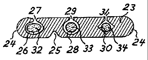
Figure 3 shows a ribbon shaped embodiment of the invention. The example shows
a ribbon
shaped structural element 23 with rounded edges 24 and a track 25 on the
bottom side for alignment
to receptacles. On top side, several options of longitudinal tracks are shown
side by side; a track 26
of elliptical cross section accessible through slit gap 27, a track 28 of
circular cross section accessible
CA 02531338 2006-01-04
WO 2005/027147
PCT/N02004/000214
7
through slit gap 29, and a track 30 of square cross section accessible through
slit gap 31. In practice,
tracks may be uniform in a single string device, so that the illustration
primarily shows the various
options.
In the tracks 26, 28, 30 a conductor 32, 33, 34 is shown in each track. The
conductors 32-34 may
be of different shape, structure and function. By principle, any kind of
single conductor, with or
without insulation, may be used, being of a metallic or optical medium. Copper
conductors may be
protected by glass fibre which offers high resistance in fires. One may put
twisted pairs in tracks to
provide increased shielding.
Figures 4 and 5 show a further embodiment of a string device according to the
invention, and an
embodiment of the connector system according to the invention. The string
device in this case is
basically a circular core 35 with 5 C shaped tracks 36-40 at the perimeter.
Each track 36-40
incorporates a conductor 41-45 in a similar way as per Figure 3. The track
slits in 36-40 is designed
with tight lips which are just flexible enough to allow pressing in the
conductors 41-45.
Sample of conductors are copper, aluminium, full or semi conducting polymers
and optical fibres
including nano fibres.
Figures 4 and 5 also show an example of receptacle for connection according to
the invention.
'Receptacle' refers to various forms of terminating conductors to splices,
circuit boards or other
hardware components where the main function is to transmit signals or power
between conductors
and equipment, such as in vehicles, electrical panels, and alarm systems.
The example of a connector system is a cylindrical splice receptacle 46, shown
with a string
device inserted at each end. The receptacle 46 is basically shaped as a
cylinder with an internal
alignment ridge 47 to couple with track 48 in the string device cores 35.
Corresponding to each
conductor 36-39, longitudinal contacts are shaped as knives 49-52, so as to
both cut into slits and to
make sustained contact with the conductors, in order either to splice the
conductor within the two
inserted string devices, or to provide an external connection and connection
point, possibly both.
The example shows a receptacle with electrically conducting terminals 53-56,
each of which is in
contact with a respective 'knife' element 49-52.
At each end of the receptacle 46, one or several hooks 57 and 58 are arranged,
to prevent the
string device being unintentionally pulled out of the receptacle. At track 40,
a fibre optical
transceiver device 59 is connected to an external signal circuit which picks
up or sends signals via
the fibre optic conductor 45.
The string device, may be insulated by an outer sheath, but is not necessary
where there is no
contact danger voltage. The conductors have fixed interrelated positions. Use
without an outer sheath
means that the cable does not have to be stripped before connection, and all
conductors will meet up
to the corresponding contacts of a receptacle when a cable end is manually
pushed into the multi
contact receptacle in one single operation. Receptacles have knives or spring
loaded contact elements
CA 02531338 2006-01-04
WO 2005/027147 PCT/N02004/000214
8
as described above that positively contact the respective conductors through
the slits. Receptacles
may be designed two-sided, forming splices or patch cables for line heat
detectors or cables of short
lengths, or designed as adapters to conventional terminals. Receptacles may be
designed so that a
cable may be pulled through it without breaking any circuit. Thus allowing and
allowing components
to be moved along the cable while remaining fully operational.
The string device and receptacle have corresponding non symmetric cross
sections that align
conductors, allowing them to fit but one way, so that wrong connections are
impossible and there is
no need for color coding conductors. The cable is characterized by that it may
be small, circular and
flexible.
The string device according to the invention, when applied as a cable,
provides much stronger
protection against bending of the plug pins, than for conventional cables with
conductor cores. This
inherent strength is further enhanced with example embodiments shown in
Figures 3 and 4. The
connection system makes use of a crimping tool to connect multi-conductor
cables.
The invention allows for simplification of connecting fibre optic cables.
Light transceivers may be
positioned in a star shape around the perimeter of the multi-conductor string
device. Fibres may be
tightly spaced and not interfere with each other.
The string device, according to the invention, lends itself well fitted as
cables for vehicles,
electrical installations, for example switch boards and termination cabinets.
Processing
Manufacturing the string device as shown in Figures 1 and 2, may be
accomplished by pulling the
core, the structural element, through a die of proper dimension and cross
sectional shape from liquid
silica or spun fibres. It is then coated with a melting alloy by known
processes for metal coating of
fibres.
Another technique is sputter deposition by magnetrons. Other known techniques
for metal coating
are, but not limited to those that, utilize evaporation, chemical
decomposition and electro deposition.
By a special process irregular cross section string devices are shaved on
protruding ridges after the
application of the metal coating, leaving longitudinal tracks of conducting
and non conducting
material side by side, effectively creating discrete conducting tracks, such
as those according to
Figure 2.
A string device according to the invention, designed as a heat line sensor,
may be pressed into a
slit, or glued upon, the dielectric outer sheath of known power cables.
The invention may also be realized by tube conductors which operate fluid
mechanically, i.e.
pneumatic or hydraulic.