Note: Descriptions are shown in the official language in which they were submitted.
CA 02531442 2006-01-05
WO 2005/005322 PCT/US2004/021664
DEVICES AND PROCESSES FOR USE IN ULTRASOUND TREATMENT
FIELD
[0001] In specific embodiments, the present invention is directed to
using high-
frequency, low-energy ultrasound to treat cutting fluids. In other distinct
embodiments, the
present invention is directed to using high-frequency, low-energy ultrasound
to treat
fountain solutions.
BACKGROUND
[0002] The cutting of metals and other hard materials is often
carried out with
the use of a cutting tool to provide a desired shape, size or surface to the
workpiece. When
cutting these hard materials, frictional heat can burn the cutting tool and
make the machined
surface of the workpiece rough. Furthermore, thermal expansion lowers the
accuracy of the
shape and the size of the workpiece and the tool, thereby causing various
other problems.
To help alleviate the above problems, a cutting fluid is often employed during
cutting.
[0003] Oils are commonly used as a cutting fluid when cutting metals
and other
hard materials. One disadvantage of using a straight oil as a cutting fluid is
that it usually
has to be used at low temperatures because high temperatures can cause the
production of
fire and smoke. To help overcome this problem, an oil-water emulsion cutting
fluid having
sufficient lubricity and cooling properties, can be used as a cutting fluid.
[0004] Unfortunately, cutting fluids, especially water-based cutting
fluids, are
susceptible to bacteria and other microbial propagation. Bacterial colonies
often result in
unpleasant odors, deterioration of the cutting fluid, and serious health
hazards. In general,
there are two types of bacteria that grow in cutting fluids: aerobic, which
multiply in the
presence of oxygen, and anaerobic, which propagate in the absence of oxygen.
While the
anaerobic types can result in unpleasant odors through the production of
hydrogen sulfide,
they typically do very little actual damage to cutting fluid itself. However,
the aerobic type
seriously degrades fluids, causing corrosion inhibition and loss of lubricity.
Furthermore,
the bacterial lifecycle while "eating" the fluid concentrate also results in
the deposition of
various acids and salts. This can cause extensive rusting/corrosion of both
moving machine
parts and the material being machined.
[0005] To prevent these accompanying problems, biocides have been
added to
cutting fluids. In practice however, these agents are of limited usefulness.
In addition to
-1-
CA 02531442 2006-01-05
WO 2005/005322 PCT/US2004/021664
costing more money, there are limits on the amount of biocide which can be
incorporated
into the cutting fluid. Furthermore, these agents are often ineffective,
degrade over time,
and replacing them can be expensive. In addition, these agents and substances
often lower
the quality of the cutting fluid.
[0006] Accordingly, there is a need in the art for an effective and
new method of
treating cutting fluids, that can provide uniform protection, or substantially
uniform
protection with time, without the use of large amounts of biocides.
[0007] Other distinct embodiments of the teachings herein pertain to
the
treatment of fountain solutions used in printing systems. In general, offset
lithographic
printing employs planographic plates which transfer ink via a blanket roll to
a substrate
thereby forming printed images. The plates are referred to as planographic
because the
image and non-image areas are in the same plane. The image areas, which accept
ink, are
distinguished from the non-image areas on the plate, by being oleophilic
(having an affinity
to oil), whereas the non-image areas are hydrophilic (water accepting).
[0008] Typically, a lithographic printing plate is covered with a
thin film of
fountain solution which prevents the ink from covering the plate in the non-
image areas.
More specifically, the fountain solution helps maintain the non-image areas of
the printing
plate, by increasing their hydrophilic nature.
[0009] Unfortunately, fountain solutions often provide a suitable
medium for
microorganisms to propagate. Unwanted microorganisms can include, bacteria,
algae,
mold, and the like, for example. To combat this problem, anti-microbial
agents, or toxic
biocides, can be added to the fountain solution.
[0010] While biocides added to fountain solution concentrates can
afford
protection to the product in storage and shipment, they are of limited
usefulness after they
have been diluted. Even in the diluted state, some of these biocides are skin
sensitizers and
higher dosages have been reported to cause skin sensitivity and other
dermatological
problems.
[0011] In order to avoid the toxic use of biocides, UV has been
considered for
the control of microorganisms in fountain solutions. Typical UV treatment
involves killing
microorganisms through lytic processes, wherein cell membranes and cellular
components
are decomposed. While UV light can function somewhat effectively in relatively
clean
water, when a solution is dirty or contains a number of compounds, the
effectiveness of UV
light decreases. This decrease in effectiveness generally occurs because these
additional
-2-
CA 02531442 2011-06-29
compounds in the solution absorb a significant amount of the UV energy.
Furthermore, the
use of UV rays can chemically or physically alter the fountain solution, such
as to
negatively effect its intended purpose.
[0012]
Smith, in U.S. Patent No. 6,503,449 discloses treating water-based
suspensions with high-energy, low-frequency ultrasound. In addition to
requiring high-
energy, this process is dependent upon using toxic biocides to treat the
suspensions.
[0013]
Accordingly, there is a need in the art for an effective, low-energy, high-
frequency method of treating fountain solutions without the use, or with
limited use, of
toxic biocides, and without compromising the effectiveness of the fountain
solution.
Furthermore, there is a need to provide a treatment that will provide
microorganism control
throughout the fountain solution system and in a manner which will provide
substantially
uniform protection with time.
SUMMARY OF THE INVENTION
Accordingly, the invention in one aspect, provides a method of treating a
cutting fluid comprising:
collecting cutting fluid from a cutting device;
simultaneously exposing said cutting fluid to low-power ultrasound of a
frequency of 200 kHz or higher while injecting gas into the ultrasound field,
wherein
the treatment does not deteriorate the lubricity characteristics or pH of the
fluid; and
2 0 recirculating the treated cutting fluid to the cutting device.
Another aspect of the invention provides an apparatus for reducing the
presence of live microorganisms in a cutting fluid comprising:
a cutting device;
a cutting fluid circuit connected to the cutting device;
a compartment for holding a reservoir of cutting fluid wherein said cutting
fluid
is routed;
an ultrasound emitter configured to emit low-power ultrasound signals at a
frequency higher than 200 kHz into said compartment;
3
CA 02531442 2011-06-29
a gas microbubble emitter configured to emit gas bubbles having an average
diameter of less than 1 mm into the ultrasound field in the compartment
containing
the cutting fluid, wherein the emitted ultrasound and gas do not deteriorate
the
lubricity characteristics or pH of the fluid; and
a cutting fluid distributor in communication with the compartment and
configured to recirculate cutting fluid to the cutting device.
Still another aspect of the invention provides a method of treating cutting
fluid
comprising:
collecting cutting fluid from a fluid routing circuit;
routing said cutting fluid into a compartment;
simultaneously exposing said cutting fluid in compartment to low-power
ultrasound of a frequency of 200 kHz or higher while injecting gas into the
ultrasound
field, wherein the treatment does not deteriorate the lubricity
characteristics or pH of
the fluid.
Yet another aspect of the invention provides a machining system comprising:
a cutting device;
a cutting fluid circuit connected to the cutting device;
a compartment in the cutting fluid circuit for holding a reservoir of cutting
fluid
through which said cutting fluid is routed;
an ultrasound emitter configured to emit low-power ultrasound signals at a
frequency higher than 200 kHz into said compartment;
and a gas bubble emitter configured to emit gas bubbles into the ultrasound
field in the compartment containing the cutting fluid, wherein the emitted
ultrasound
and gas do not deteriorate the lubricity characteristics or pH of the fluid.
Still another aspect of the invention provides a method of treating a fountain
solution comprising:
collecting fountain solution from a print plate;
simultaneously exposing said fountain solution to gas bubbles and low-power
ultrasound of a frequency of 100 kHz or higher while injecting gas into the
ultrasound
3a
CA 02531442 2011-06-29
field, wherein the treatment does not chemically or physically alter the
fountain
solution so as to negatively effect its intended purpose; and
recirculating the fountain solution.
Another aspect of the invention provides an apparatus for reducing the
presence of live microorganisms in a fountain solution comprising:
a print plate;
a compartment for holding a reservoir of fountain solution;
an ultrasound emitter configured to emit low-power ultrasound signals at a
frequency higher than 100 kHz into said compartment;
a gas bubble emitter configured to emit gas bubbles into the ultrasound field
in
the compartment containing the fountain solution, wherein the treatment does
not
chemically or physically alter the fountain solution so as to negatively
effect its
intended purpose; and
a circulation system configured to transfer fountain solution to the
compartment, and to return the fountain solution to the print plate.
Still another aspect of the invention provides a method of treating fountain
solution comprising:
collecting said fountain solution from a fluid routing circuit;
routing said fountain solution into a compartment; and
simultaneously exposing said fountain solution in compartment to low-power
ultrasound of a frequency of 100 kHz or higher while injecting gas into the
ultrasound
field, wherein the treatment does not chemically or physically alter the
fountain
solution so as to negatively effect its intended purpose.
Yet another aspect of the invention provides a machining system comprising:
a printing apparatus;
a fountain solution circuit connected to the printing apparatus;
a compartment for holding a reservoir of fountain solution through which said
fountain solution is routed;
an ultrasound emitter configured to emit low-power ultrasound signals at a
frequency higher than 100 kHz into said compartment; and
3b
CA 02531442 2011-06-29
a gas bubble emitter configured to emit gas bubbles into the ultrasound field
in
the compartment containing the fountain solution, wherein the treatment does
not
chemically or physically alter the fountain solution so as to negatively
effect its
intended purpose.
BRIEF DESCRIPTION OF THE DRAWINGS
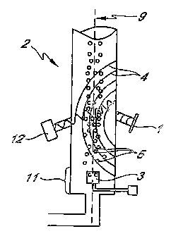
[0014] Figure 1 is a drawing showing one embodiment of an
ultrasound/microbubble device described herein.
[0015]
Figure 2 is a drawing showing a recirculating cutting fluid system
comprising a ultrasound/microbubble device connected to a cutting fluid
distributor and a
cutting fluid collection device.
[0016]
Figure 3 is a drawing showing a recirculating fountain solution system
comprising a ultrasound/microbubble device connected to a printing apparatus.
[0017]
Figure 4 is a drawing showing a recirculating roll forming system
comprising a ultrasound/microbubble device.
DETAILED DESCRIPTION
Section I: Devices and Methods for Treating Cutting Fluids
[0018]
The teachings herein are directed in part towards devices and methods
which can neutralize, prevent the growth of, and remove microorganisms present
in a
cutting fluid. In further embodiments, the devices and methods provided herein
can treat
cutting fluids suspected of containing microorganisms, for example.
[0019]
Cutting fluid degrades with time, based in part to microbial (e.g.,
bacterial) growth and contamination from the machining operation. When it
becomes
uneconomical to maintain the cutting fluid by regular make-up operations, the
cutting fluid
is typically disposed of. Accordingly, the embodiments herein encompass
extending the
3c
CA 02531442 2012-06-13
useful life of cutting fluid by preventing degradation caused by microbes. In
further
embodiments, where the cutting fluid has degraded to a point where its utility
has expired,
the methods herein can be used to bring the cutting fluid to a safe level
(neutralizing
microbial propagation) prior to disposal (e.g., releasing the cutting fluid
flow into a sewer
system).
Devices and Methods
[0020] Embodiments of the devices described herein can be found in
U.S.
Application No. 10/358445 and U.S. Patent No. 6,540,922 to Cordemans et al.
Methods of treating
cutting fluids can be performed with the devices disclosed herein. One
particular
embodiment of a device that can be used for treating cutting fluid is
represented in Figure 1.
In certain embodiments, the cutting fluid to be treated can contain
microorganisms,
including bacteria, viruses, fungi, protists, and the like, for example.
[0021] Referring to Figure 1, the devices described herein can include
a
compartment 2, preferably in the shape of a cylinder or a rectangular cross-
section. In
further embodiments the compartment 2 can be in communication with a reservoir
(not
shown) which holds the cutting fluid to be treated. The term "reservoir" is to
be construed
broadly, and generally relates to an apparatus containing cutting fluid. In
specific
embodiments the devices provided herein are connected (e.g., via a side
stream) through
the sump to the recirculating cutting fluid. In further embodiments, the
devices provided
herein are not in communication with a reservoir and are directly connected to
the cutting
fluid to be treated.
[0022] In further embodiments, the compartment 2 contains (e.g., along
its
wall) one or more high-frequency ultrasound emitters 1 that emit ultrasound 4
into the
compartment 2 (preferably into the center of this compartment 2). In other
embodiments
the container can also have one or more microbubble emitters 3 for emitting
gas
microbubbles 5, which are arranged so as to emit the gas microbubbles 5 into
the
ultrasound 4 field emitted in the compartment 2.
[0023] The term "microbubbles," as used herein is intended to refer to
gas
bubbles with an average diameter of less than 1 mm. In some embodiments the
diameter is
less than or equal to 50 Rm. Still in other embodiments the microbubbles have
a diameter
less than about 30 Inn. In certain embodiments the microbubbles are selected
from air,
4
CA 02531442 2006-01-05
WO 2005/005322 PCT/US2004/021664
oxygen, and ozone microbubbles. To lower operating costs, it can be
advantageous to use
microbubbles that are not ozone microbubbles, such as air microbubbles.
[0024] The term "microorganisms" is synonymous with microbes and
generally
relates to pathogenic or non-pathogenic microorganisms which can give rise to
harmful
effects to cutting instruments (e.g., machinery, tools, etc.), man, mammals or
any other
animal. Such microorganisms can include both aerobic and anaerobic bacteria
(e.g.,
Yersenia, Staphylococcus, E. coli, Pseudomonas aeruginosa, Pseudomonas
oleovorans,
Paracolobactrum, Proteus vulgaris, Klebsiella pneumoniae, Micrococcus
pyogenes,
Aerobacter aerogenes, Citrobacter, Achroinobacter), viruses (e.g., HIV, HCV,
HB V), fungi
(e.g., Fusarium, Cephalosporium, Cladosporiwn, Aspergillus), protists (e.g.,
mold, algae),
and the like, for example.
[0025] In specific embodiments, the methods and devices herein
include low
energy, high-frequency ultrasound to treat a cutting fluid. The term "high
frequency" is
intended to refer to frequencies higher than 200 kHz and up to several MHz. In
certain
embodiments, the high frequencies used are between 200 kHz and 10 MHz. In
still other
aspects, the high-frequencies can be between 200 kHz and 20 MHz. In various
other
embodiments, the high-frequencies can be between 800 kHz (where less radical
effects and
more biological effects are reached) and 5 MHz. In another embodiment, the
frequency
used is between 1 MHz and 3 MHz. More specifically, the frequency can be about
1.8
MHz.
[0026] In various embodiments of the methods and devices described
herein,
the microbubble emitter 3 for emitting gas microbubbles 5 is arranged at the
base 11 of the
compartment 2, (i.e., at the bottom of the compartment 2), such that the
microbubbles
move by rising naturally or by entrainment of the gas in the flow of the
cutting fluid.
[0027] In still further embodiments, the devices and methods
provided herein,
neutralize, treat or prevent the growth of microorganisms in a cutting fluid.
Although the
present teachings are in no way to be limited by their precise mechanism of
action, in more
specific embodiments the devices provided herein can produce radicals such as
FP, 'OH
and H00'. These radicals can also form H202, which along with the radicals, is
toxic to
microorganisms and can bring about their inactivation and/or destruction.
[0028] The species created are thought to be derived from the
reactions of high-
frequency ultrasound on the water molecule, most likely giving rise (in
particular in the
presence of oxygen) to the following reactions:
-5-
CA 02531442 2006-01-05
WO 2005/005322 PCT/US2004/021664
H20 ---> H + 'OH
H' + 02 --> HOO'
HOO' + HOO' H202 02,
0H+ 'OH --> H202
[0029] Advantageously, the energy required to produce these toxic
species is
reduced if the process is performed in the presence of microbubbles, as
described herein.
[0030] It has been recently appreciated that the injection of
microbubbles into
the ultrasound field gives rise to an increase in the phenomenon of
sonoluminescence, by
superposition of the microbubbles onto the cavitation bubbles induced by the
ultrasound,
the number of excited and toxic species can be multiplied. This phenomenon is
observed
on a macroscopic level when the ultrasound treatment is synergistically
combined with the
presence of microbubbles of suitable size.
[0031] In additional embodiments, the devices and methods provided
herein
have the advantage that there is no need to devote the ultrasound to specific
zones, since it
is observed that the treatment system functions by diffusing the products
formed in situ (for
example, ROS (reactive oxygen species), radicals and H202 formed) towards the
reservoir
of the cutting fluid to be treated.
[0032] In further embodiments, the one or more ultrasound emitters 1
in the
devices described herein are oriented so as not to give rise to practically
any standing-wave
phenomena. For example, in certain embodiments, one or more ultrasound
emitters 1 can
be oriented obliquely relative to the axis 9 of the compartment 2 (acute angle
not
perpendicular to this axis 9) and relative to the flow of cutting fluid and to
the flow of
microbubbles 5 (see Figure 1). This characteristic makes it possible for all
the
microbubbles 5 in the compartment 2 to be treated in a statistically identical
manner,
without creating stationary zones in the said compartment 2. Accordingly,
certain
embodiments herein are directed to devices and methods that provide uniform
treatment, or
substantially uniform treatment, and protection over time.
[0033] According to other embodiments, the devices and methods
described
herein can include a light emitter 12 (i.e. an electromagnetic radiation
emitter) which emits
into the compartment 2 in the ultrasound 4 field, radiation, with a frequency
that is mostly
in the visible range. However, for certain applications, in order to remove
certain specific
microorganisms, it can be advantageous to emit electromagnetic radiation with
a frequency
-6-
CA 02531442 2006-01-05
WO 2005/005322 PCT/US2004/021664
that is mostly non-visible, as ultraviolet radiation (e.g., UVA, UVB or UVC
type), infrared,
laser, microwaves, and the like, for example.
[0034] It has recently been discovered, unexpectedly, that a
treatment
comprising the emission of microbubbles into the fields combined with
ultrasound and light
radiation is particularly effective at inactivating and removing
microorganisms present in a
cutting fluid, and preventing their growth. The phenomenon of sonoluminescence
can
promote the production of extremely active oxygenated species (often
referenced as ROS
(reactive oxygen species) such as the superoxide radical, 'OH, or singlet
oxygen, which can
result in a series of biochemical reactions that are extremely toxic for
certain
microorganisms.
[0035] In various embodiments, the teachings herein are directed
towards
devices which do not require additional chemical products (e.g., biocides,
photosensitizers)
to neutralize or prevent the growth of microorganisms from a cutting fluid. In
other
embodiments the methods and devices herein can be used in conjunction with
additional
chemical agents.
[0036] In other embodiments, the devices and methods described
herein can
include a pump or other devices for recirculating the cutting fluid, as well
as devices for
recovering the microorganisms present in the cutting fluid. Examples of
devices for
recovering the microorganisms, non-exclusively include apparatuses for
filtration,
centrifugation, and precipitation (such as cyclones, and the like). In certain
embodiments,
the pump and/or devices for recovery are arranged between the reservoir
containing the
cutting fluid, to be treated and the compartment 2.
[0037] In certain embodiments, the devices provided herein can be
connected to
a cutting fluid distributor and/or cutting fluid collection system (e.g., a
trench or sump).
For example, Figure 2 represents a recirculating cutting fluid system 21
comprising a
ultrasound/microbubble treatment device connected to a cutting fluid
distributor 20 and a
cutting fluid collection device 22. In further embodiments, the cutting fluid
to be treated
may be applied either manually to the cutting zone 24 of the tool, or
delivered in a mist. In
specific embodiments, the cutting fluid is distributed in a continuous stream,
delivered by a
pump and directed through a nozzle 26 to the cutting edge 28 of the machine
tool or
through the tool and over the work to carry away the work material chips or
swarf. In other
embodiments, a variety of fluid nozzle designs can be used depending on the
specific
application needed. In still further embodiments, a distribution system 20 can
be used to
-7-
CA 02531442 2012-08-30
control the cutting fluid flow volume and flow pressure. In other embodiments,
the cutting
fluid can be in a recirculating system 21. Non-exclusive examples of cutting
fluid
distributors that can be used with the devices herein are disclosed in U.S.
Patent No.
6,450,738, to Ripley, and U.S. Patent No. 4,514,149, to Kanebako et al.
[0038] In further embodiments, the cutting fluid can be
collected through
gravity flow, velocity flow, or trenches (e.g., conveyorized trenches). In
specific
embodiments, after the cutting fluid is collected, it can be treated according
to the methods
provided herein and recirculated to the cutting zone of the machine tool. In
other
embodiments, the cutting fluid is not collected, and travels directly from the
cutting zone to
the devices provided herein, for treatment. A non-exclusive example of a
cutting fluid
collection system that can be used with the devices and methods herein is
disclosed in U.S.
Patent No. 5,593,596, to Bratten. In still further aspects, the devices and
methods herein can be
used with any suitable cutting fluid monitoring and/or control system, such as
those disclosed in
U.S. Patent No. 5,224,051, to Johnson, for example.
[0039] The methods and devices herein can be used to treat
practically any type
of cutting fluid used with any suitable instrument (e.g., machine) capable of
cutting or
manipulating hard materials, such as metals, and the like, for example. The
term "cutting"
is to be construed broadly, and encompasses all types of hard material (e.g.,
metal)
manipulations. In certain embodiments, the term "cutting" can relate to
planing, boring,
broaching, counter-boring, forming, threading, shaping, hole extruding,
milling, sawing,
drilling, spot facing, tapping, hobbing, drawing, engraving, piercing,
internal breaching,
reaming, punching (e.g., using a punch press), roll forming, seat forming,
stamping,
turning, diamond wafering, and the like, for example. Accordingly, the methods
and
devices herein can be used with any suitable instrument or machine that is
capable of the
above listed functions, or like functions. For example, suitable instruments
and machines
include: milling cutters, broaching machines, boring machines, counter-boring
machines,
forming machines, boring mills, saws (e.g., circular and band), grinders
(e.g., belt and
wheel), drilling machines, punch presses, and the like.
[0040] In some particular embodiments, as mentioned above and
shown in one
embodiment in Figure 4, the methods and devices described herein can be used
to treat
8
CA 02531442 2006-01-05
WO 2005/005322 PCT/US2004/021664
fluids used in roll forming systems, such as rolling oil emulsions. In more
specific
embodiments the teachings herein can be used to treat rolling 'oil emulsions
used in
aluminum rolling. Treating rolling oil emulsions with the methods and devices
herein do
not deteriorate the lubricity characteristics or pH of the fluid. Furthermore,
the teachings
herein prevent foul odors from developing, and prevent biological waste from
blocking
filters within the system. In preferred embodiments, the methods and devices
herein can
treat rolling oil emulsions at temperatures between 35 C-60 C.
[0041] In certain embodiments, the methods and devices provided
herein can
treat each cutting fluid used by a particular cutting instrument, regardless
of whether the
cutting instrument is using one or more types of cutting fluids, or is
connected to one or
more cutting fluids reservoirs.
[0042] The methods and devices herein can be used to treat any
suitable type of
cutting fluid currently available or that will be available in the future. The
term "cutting
fluid" is to be construed broadly and generally relates to fluids used as a
lubricant, cooling
agent, anti-welding agent, or corrosion inhibitor in cutting hard materials,
such as metal,
and the like, for example. In certain embodiments the term "cutting fluid"
encompasses
metal working fluid (MWF). In other embodiments, the term "cutting fluid"
encompasses
fluid used to treat, manipulate or cut other hard materials, such as: glass,
ceramics, carbides,
minerals, earthenware, diamonds and other precious stones, plastics, and the
like, for
example.
[0043] Based on the above-mentioned functions, cutting fluids can
lead to
longer tool life, reduced thermal deformation of workpiece, a better surface
finish, and ease
of chip and swarf handling, and the like, for example.
[0044] Practically any cutting fluid, including any of the following
three general
categories of cutting fluids, can be used with the devices and methods
described herein:
soluble-oils, semisynthetic fluids, and synthetic fluids.
[0045] In certain embodiments, the methods and devices herein can be
used to
treat synthetic cutting fluids. Synthetic fluids generally contain no
petroleum or mineral oil
base and instead are formulated from alkaline inorganic and organic compounds.
Synthetic
cutting fluids can include synthesized hydrocarbons, organic esters,
polyglycols, phosphate
esters, organic or inorganic salts, and other synthetic lubricating fluids. In
addition,
synthetic cutting fluids can include additives, such as agents that inhibit
corrosion.
Synthetic fluids are often used in a diluted form. For example, each part of
synthetic
-9-
CA 02531442 2006-01-05
WO 2005/005322 PCT/US2004/021664
concentrate can be diluted with about 9-41, 10-40, 11-40, 11-39, 10-35, and 10-
30 parts
water. Synthetic fluids often provide the best cooling performance among all
cutting fluids,
but generally do not provide optimal lubrication.
[0046] In still further embodiments, the methods and devices herein
can be used
to treat soluble-oil cutting fluids. Although used throughout the industry,
the term
"soluble-oil," is typically a misnomer because the constituents are generally
not soluble in
water. Soluble-oils are generally oils (e.g., mineral and petroleum) blended
with
emulsifiers and/or other additives which, when added to water and stirred,
form an oil-in-
water emulsion. The emulsion allows the good cooling properties of water to be
utilized in
the metal working process while the oil and any other additives can provide
lubrication and
corrosion inhibiting properties, for example. Usually, the concentrate
includes a base
mineral oil and one or more emulsifiers to help produce a stable emulsion.
Superfatted
emulsions are typically produced by the addition of fatty oils, fatty acids,
or esters.
Extreme pressure emulsions can include additives such as chlorine, chlorinated
paraffins,
sulfur, phosphorus, and the like, for example.
[0047] Typically, soluble-oil cutting fluids provide good
lubrication and heat
transfer performance. Furthermore, soluble-oil cutting fluids are widely used
in industry
and are usually the least expensive among all cutting fluids. Soluble-oil
cutting fluids are
also known as water-based oils, water-based soluble oils, water-based
emulsifying oils,
emulsifying oils, water-soluble oils, and the like.
[0048] Oils are typically diluted in soluble-oil cutting fluids. For
example, in
certain embodiments, the oil can constitute about 3%, 4%, 5%, 6%, 7%, 8%, 9%,
or 10% of
the cutting fluid. In certain embodiments, the water used in soluble-oil
cutting fluids is
deionized or softened. In other embodiments, the water used can include about
70-140, 80-
125, or 90-115 ppm of calcium carbonate.
[0049] In other embodiments, the methods and devices herein can be
used to
treat semi-synthetic cutting fluids. Semi-synthetic cutting fluids generally
relate to a
combination of synthetic and soluble-oil fluids and have characteristics
common to both
types. The cost and heat transfer performance of semi-synthetic fluids
typically lie between
those of synthetic and soluble-oil fluids.
[0050] Depending on the specific type of cutting fluid to be treated
with the
methods herein, the cutting fluid can contain water, oil, and one or more
emulsifiers,
chelating agents, coupling agents, viscosity index improvers, detergents,
plasticizers, anti-
-10-
,
CA 02531442 2012-06-13
mist agents, anti-weld agents, oiliness agents, surfactant wetting agents,
dispersants,
passivators, anti-foaming agents, alkaline reserves, dyes, odorants, corrosion
inhibitors,
extreme pressure additives, lubricity enhancers, cleaners, tapping compounds,
fingerprint
neutralizers, or any other suitable additive, for example.
[0051] In
some embodiments, the devices and methods provided herein can be
used in conjunction with anti-microbial agents such as a amine, amide, phenyl,
guanidine,
prochloraz, propiconazole,
iodocarb, sodium hypobromite, 5-Chloro-2-methyl 4-
isothiazolin-3-one, 2-methyl-4-isothiazolin-3-one, 3-Isothiazolone (which can
be stabilized
with antimony salts), Tris(hydroxymethypnitromethane, Hexahydro-1,3,5-tris(2-
hydroxyethyl)-S-triazine,
Hexahydro-1,3,5-triethyl-S-triazine, 1 -(3-Chloroally1)-3,5 ,7-
triaza-1 -azonia adamantane
chloride, 4-(2-Nitrobutyl)morpholine-4,4'-(2-ethy1-2-
nitrotrimethylene) dimorpholine, 0-Phenyl phenol, Sodium 2-pyridinethio1-1-
oxide, 1,2-
BIT, 6-Acetoxy-2,4-dimethyl-m-dioxane, 2,2-Dibromo-3-nitrilopropionamide, p-
Chloro-m-
xylenol, and the like. Non-exclusive examples of microbiocides are also
provided in U.S.
Patent No. 6,342,522, to Mason et al., U.S. Patent No. 6,322,749, to McCarthy
et al., U.S.
Patent No. 5,416,210, to Sherba et al., U.S. Patent Nos. 4,975,109 and
5,256,182, to
Friedman, Jr. et al., U.S. Patent No. 5,145,981, to Willingham, U.S. Patent
No. 4,294,853,
to Williams et al.
100521 While
in some embodiments the methods and devices herein can be used
with microbiocides, such as those described above, it is important to note
that the
effectiveness of the provided methods and devices in treating, preventing the
growth of or
neutralizing microorganisms is not dependent on additional chemicals (e.g.,
biocides).
Accordingly, the methods and devices described herein can be used without anti-
microbial
agents.
[0053]
Examples of cutting fluids that the methods and devices herein can treat,
include, but are not limited to the cutting fluids disclosed in U.S. Patent
Nos. 6,518,225 and
6,242,391, to Fukutani et al., U.S. Patent No. 5,534,172, to Perry et al.,
U.S. Patent No.
6,221,814, to Kaburagi et al., U.S. Patent No. 4,605,507, to Windgassen et
al., U.S. Patent
No. 6,258,759, to Futahashi, et al., and U.S. Patent No. 5,616,544, to Kalota,
et al.
11
CA 02531442 2012-06-13
,
[0054]
Cutting fluids can be used in cutting or manipulating any suitable hard
material. In certain embodiments, the cutting fluid to be treated by the
methods herein can
be used (e.g., as a coolant or lubricant) in the cutting of any suitable type
of metal
11a
CA 02531442 2006-01-05
WO 2005/005322 PCT/US2004/021664
workpiece. In specific embodiments the workpiece can be or include: carbon,
alloy and
tool steel, stainless steel, titanium and other high-temperature alloys, grey
and ductile cast
irons, aluminum and aluminum alloys, non-ferrous materials, magnesium, copper
and
copper alloy, bronze, brass, carbon steels, stainless steels, chrome-moly
steels, vanadium,
titanium, nitalloy, inconel, monel, berylium copper, boron carbide, and the
like, for
example.
[0055] In other embodiments the cutting fluid to be treated by the
methods and
devices described herein can be used in the cutting and manipulation of hard
materials,
besides metals, including, but not limited to: glass, ceramics, carbides,
minerals, ,
earthenware, diamonds and other precious stones, plastics, and the like, for
example.
[0056] In further embodiments, the devices and methods herein can be
used in
conjunction with one or more other methods that prevent microbial propagation
including:
centrifuging, filtering, aerating, cleaning the sump, maintaining proper
concentration of
cutting fluid, removing surface tramp oil, and adding biocides, for example.
Accordingly,
in certain embodiments, the devices and methods herein relate to applying high-
frequency
ultrasound either before, after, or during one or more the above-mentioned
treatment
methods, or other anti-microbial treatments.
Section Devices and Methods for Treating Fountain Solutions
[0057] In separate embodiments, the teachings herein provide devices
and
methods for treating fountain solutions used in printing systems. Offset
printing is a
process which is based on the principle that an image area (also known as the
printing area)
of a printing plate accepts ink while a non-image area (also known as the non-
printing area
or the background) repels ink. Using offset printing, the ink-coated image is
ultimately
transferred to a substrate, such as paper, producing an image corresponding to
the image on
the plate.
[0058] In general, the term "fountain solution," also known as
"dampening
fluid," relates to a solution that is applied to the surface of the printing
plate in order to
cause the non-image area of the plate to repel ink while allowing the image
area to accept
ink. Fountain solutions can also be used to quickly clean ink off the non-
image area during
press starts, promote fast spreading of water over the plate surface, help
water flow evenly
through the dampening rollers, lubricate the plate and blanket, or control
emulsification of
ink and water, and the like.
-12-
CA 02531442 2012-06-13
[0059] With
reference to Figure 3, fountain solution within the printing system
is typically collected in one or more fountain solution reservoirs, commonly
called trays 32.
In general, one or more rollers 38 positioned in a tray 32 can transfer the
fountain solution
from the tray 32 to a print plate 34. After fountain solution is transferred
to the printing
plate 34, ink rollers 36 transfer ink to the printing plate 34. A circulation
system 30 is often
used to recirculate fountain solution from a fountain solution outlet of the
tray(s) 32 to a
sump and back through a fountain solution inlet to the tray(s) of the printing
system. A
common way of driving the fountain solution from the fountain solution trays
to the sump
is by gravity feed or gravity-assisted feed, while a pump returns the fountain
solution from
the sump back to the fountain solution trays of the printing system.
[0060] A
common problem for fountain solutions is that they degrade with time,
based in part to microbial growth and contamination from the machining
operation. When
it becomes uneconomical to maintain the fountain solution by regular make-up
operations,
the fountain solution is typically disposed of.
[0061]
Accordingly, the teachings herein are in part directed towards devices
and methods which can neutralize, prevent the growth of, and remove
microorganisms in a
fountain solution. More specifically, the embodiments herein include extending
the useful
life of a fountain solution by preventing degradation caused by
microorganisms. In further
embodiments, where the fountain solution has degraded to a point where its
utility has
expired, the methods herein can be used to bring the fountain solution to a
safe level
(neutralizing microbial propagation) prior to disposal.
Methods and Devices
[0062]
Embodiments of the devices provided herein can be found in U.S.
Application No. 10/358445 and U.S. Patent No. 6,540,922 to Cordemans et al.
Methods of treating
fountain solutions can be performed with the devices disclosed herein. One
particular
embodiment of a device that can be used for treating fountain solution is
represented in
Figure 1. In certain embodiments, the fountain solution to be treated can
contain
microorganisms, including bacteria, viruses, fungi, protists, and the like,
for example.
[0063]
Referring to Figure 1, the devices described herein can include a
compartment 2, preferably in the shape of a cylinder or a rectangular cross-
section. In
13
CA 02531442 2012-06-13
further embodiments the compartment 2 can be in communication with a reservoir
(not
shown) which holds the fountain solution to be treated. The term "reservoir"
is to be
1 3a
CA 02531442 2006-01-05
WO 2005/005322 PCT/US2004/021664
construed broadly, and generally relates to an apparatus containing fountain
solution. In
specific embodiments the devices provided herein are connected (e.g., via a
side stream) to
a fountain solution distribution, supplying, collecting, mixing, or
circulating system. In
further embodiments, the devices provided herein are not in communication with
a
reservoir, but are directly connected to the fountain solution to be treated.
'
[0064] In other embodiments, the compartment 2 contains (e.g., along
its wall)
one or more high-frequency ultrasound emitters 1 that emit ultrasound 4 into
the
compartment 2, preferably into the center of the compartment 2. In other
embodiments, the
container can also have one or more gas microbubble emitters 3 for emitting
gas
microbubbles 5, which are arranged so as to emit the gas microbubbles 5 into
the
ultrasound 4 field emitted in the compartment 2.
[0065] The term "microbubbles," as used herein is intended to refer
to gas
bubbles with an average diameter of less than 1 mm. In some embodiments, the
diameter is
less than or equal to 50 pm. Still in other embodiments, the microbubbles have
a diameter
less than about 30 pm. In certain embodiments, the microbubbles are selected
from air,
oxygen, and ozone microbubbles. To lower operating costs, it can be
advantageous to use
microbubbles that are not ozone microbubbles, such as air microbubbles.
[0066] The term "microorganism," is synonymous with "microbe", and
generally relates to any pathogenic or non-pathogenic microorganism which can
give rise to
harmful effects to the printing system (e.g., fountain solution, printing
plates, machines,
instruments), man, mammals or any other animal. Such microorganisms can
include both
aerobic and anaerobic bacteria (e.g., Yersenia, Staphylococcus, E. coli,
Pseudomonas
aeruginosa, Pseudonzonas oleovorans, Paracolobactrum, Proteus vulgaris,
Klebsiella
pizeumoniae, Micrococcus pyogenes, Aerobacter aerogenes, Citrobacter,
Achromobacter),
viruses (e.g., HIV, HCV, HBV), fungi (e.g. Fusariunz, Cephalosporium,
Cladosporiwn,
Aspergillus), protists (e.g., mold), and the like.
[0067] In specific embodiments, the methods and devices herein
include low
energy, high-frequency ultrasound to treat a fountain solution. The term "high
frequency"
is intended to refer to frequencies higher than 200 kHz and up to several MHz.
In certain
embodiments, the high frequencies used are between 200 kHz and 10 MHz. In
still other
aspects, the high-frequencies can be between 200 kHz and 20MHz. In various
other
embodiments, the high-frequencies can be between 800 kHz (where less radical
effects and
more biological effects are reached) and 5MHz. In another embodiment, the
frequency
-14-
CA 02531442 2006-01-05
WO 2005/005322 PCT/US2004/021664
used is between 1 MHz and 3 MHz. More specifically, the frequency can be about
1.8
MHz.
[0068] In
various embodiments of the methods and devices described herein,
the gas microbubble emitter 3 for emitting gas microbubbles 5 is arranged at
the base 11 of
the compai ________________________________________________________________
tinent 2, (i.e., at the bottom of the compartment 2), such that the
microbubbles
move by rising naturally or by entrainment of the gas in the flow of the
fountain solution.
[0069] In
still further embodiments, the devices and methods described herein
can neutralize, treat or prevent the growth of microorganisms in a fountain
solution.
Although the present teachings are in no way to be limited by their precise
mechanism of
action, in more specific embodiments the devices provided herein can produce
radicals such
as ROO', H, OH and HOO which can also form H202. This molecule and/or these
radicals being toxic to microorganisms and thus bring about their inactivation
and/or
destruction.
[0070]
The species created are thought to be derived from the reactions of high-
frequency ultrasound on the water molecule, most likely giving rise (in
particular in the
presence of oxygen) to the following reactions:
H2O¨>H+ 'OH
H' + 02 --> HOO'
HOO' + HOO. ¨> H202 + 02,
= OH + 'OH --> H202
[0071]
Advantageously, the energy utilized to produce these toxic species is
reduced if the process if performed in the presence of microbubbles, as
described herein.
[0072] It
has been recently appreciated that the injection of microbubbles into
the ultrasound field gives rise to an increase in the phenomenon of
sonoluminescence, by
superposition of the microbubbles onto the cavitation bubbles induced by the
ultrasound,
the number of excited and toxic species can be multiplied. This phenomenon is
observed
on a macroscopic level when the ultrasound treatment is synergistically
combined with the
presence of microbubbles of suitable size.
[0073] In
additional embodiments, the devices and methods provided herein
have the advantage that there is no need to devote the ultrasound to specific
zones, since it
is observed that the treatment system functions by diffusing the products
formed in situ
-15-
CA 02531442 2006-01-05
WO 2005/005322 PCT/US2004/021664
(e.g., ROS (reactive oxygen species), radicals and H202) towards the reservoir
of fountain
solution to be treated.
[0074] In further embodiments, the one or more ultrasound emitters 1
in the
devices described herein are oriented so as not to give rise to any standing-
wave
phenomena. For example, in certain embodiments, one or more ultrasound
emitters can be
oriented obliquely relative to the axis 9 of the compartment 2 (acute angle
not
perpendicular to this axis 9) and relative to the flow of fountain solution
and to the flow of
microbubbles 5 (see Figure 1). This characteristic makes it possible for
practically all the
microbubbles 5 in the compartment 2 to be treated in a statistically identical
manner,
without creating stationary zones in the said compartment 2. Accordingly,
certain
embodiments herein are directed to devices and methods that provide
substantially uniform
treatment and protection over time.
[0075] According to other embodiments, the devices and methods
described
herein can include a light emitter 12 (i.e. an electromagnetic radiation
emitter) which emits
into the compartment 2 in the ultrasound 4 field, radiation, with a frequency
that is mostly
in the visible range. However, for certain applications, in order to remove
certain specific
microorganisms, it can be advantageous to emit electromagnetic radiation with
a frequency
that is mostly non-visible, as ultraviolet radiation (e.g., UVA, UVB or UVC
type), infrared,
laser, microwaves, and the like, for example.
[0076] It has recently been discovered, unexpectedly, that a
treatment
comprising the emission of microbubbles into a field, combined with ultrasound
and light
radiation is particularly effective at inactivating and removing
microorganisms present in a
fountain solution. The phenomenon of sonoluminescence can promote the
production of
extremely active oxygenated species (often referenced as ROS: reactive oxygen
species)
such as the superoxide radical, 'OH, or singlet oxygen, which can result in a
series of
biochemical reactions that are extremely toxic for certain microorganisms.
[0077] In various embodiments, the teachings herein are directed
towards
devices which do not require additional chemical products (e.g., biocides,
photosensitizers)
to neutralize or prevent the growth of microorganisms, from a fountain
solution. In other
embodiments, the devices herein can be used to neutralize, or prevent the
growth of
microorganisms in a fountain solution, with a limited amount of chemical
products (e.g.,
biocides, photosensitizers). The term "limited amount" relates to solutions
containing less
than 5 ppm of biocide. For example, a limited amount of biocide can include
about 4.9,
-16-
CA 02531442 2012-06-13
4.5, 4.0, 3.0, 2.0, 1.0, and 0 ppm, and any value or range of values between
these values.
The term "biocide" is to be construed broadly, and generally relates to any
suitable agent
that is capable of preventing or stopping the growth of microorganisms,
including bacteria,
mold, algae, fungus, viruses, protists, and the like, for example.
[0078] In
other embodiments, the devices and methods described herein can
include a pump or other devices for recirculating the fountain solution, as
well as devices
for recovering the microorganisms present in the fountain solution. Examples
of devices
for recovering, non-exclusively include apparatuses for filtration,
centrifugation, and
precipitation (such as cyclones, and the like). In certain embodiments, the
pump and/or
device for recovery are arranged between the reservoir containing the fountain
solution, to
be treated and the compartment 2.
[0079] In
certain embodiments, the devices and methods provided herein can be
connected to a practically any fountain solution distribution, mixing,
collection, supply, or
circulating system. In more specific embodiments, the devices herein can be
connected to
the fountain solution systems disclosed in U.S. Patent No. 6,508,069, to
Sibilia, U.S. Patent
No. 5,713,282 to MacPhee, U.S. Patent No. 5,619,920, to MacPhee, U.S. Patent
No.
4,969,480, to Hughes, U.S. Patent No. 4,754,779, to Juhasz, U.S. Patent No.
4,523,854, to
Beckley, U.S. Patent No. 4,394,870, to MacPhee et al., and U.S. Patent No.
4,151,854 to
Patsko, for example.
[0080] New
environmental awareness as well as stringent disposal codes have
created the need for a system to treat recirculating fountain solution so that
it is maintained
relatively contaminant free. For example, in many localities the spent
fountain solution is
classified as hazardous waste. The practice of frequently discarding and
replacing the
solution has therefore become cost prohibitive. Accordingly, in further
embodiments, in
addition to treating fountain solution prior to reuse, the methods and devices
herein can be
used to make the fountain solution suitable for discarding, such as to satisfy
governing
disposal regulations, for example.
[0081]
Typically, fountain solutions primarily comprise water and additional
substances. In general, additional substances are added to the fountain
solution depending
on the specific intended use of the fountain solution. Accordingly, further
embodiments
17
CA 02531442 2012-06-13
include methods of treating fountain solutions containing agents that regulate
the pH,
ensure compatibility with the printing ink, or keep the printing plate moist.
In still further
1 7a
CA 02531442 2012-06-13
embodiments, the methods herein can treat fountain solutions containing one or
more of the
following agents: chelate formers, solvents, preservatives (including
biocides), surfactants,
corrosion inhibitors (e.g., zinc nitrate, magnesium nitrate, aluminum
nitrate), defoamers,
dyes, viscosity control agents, emulsion control agents, non-piling agents
(e.g., glycols), de-
sensitizing salts (e.g., silicates, phosphates), water soluble gums (e.g., gum
arabic, larch
gum, starches, CMC, PVP, and acrylics), or lubricants (e.g., alcohol, alcohol
substitutes,
polymers, and glycols), and the like.
[0082] Typical biocides that can be can be used in limited amounts
with the
methods described herein, include Bromopol [1,3-propanediol, 2-bromo-2-nitro],
various
isothiazolones, glutaraldehyde, sodium benzoate, phenol, 6-acetoxy-2,4-
dimethyl-m-
dioxane, 1,2-benziso-thiazolin-3-one, 2-Rhydroxymethyl) amino]ethanol,
formaldehyde,
quaternary ammonium salt of the trialkyl benzyl type, and the like.
[0083] In more specific embodiments, the methods and devices provided
herein
can be used to treat fountain solution used in practically any type of offset
printing, or
printing that is based on water and oil being immiscible. In even more
specific
embodiments, the methods and devices herein can be used to treat fountain
solution used in
practically any lithographic printing system.
[0084] Examples of fountain solutions that the methods and devices
herein can
treat, include, but are not limited to the fountain solutions disclosed in
U.S. Patent No.
5,897,693, to Whitehead, U.S. Patent No. 5,720,800, to Matsumoto, U.S. Patent
No.
5,695,550 to Marx, et al., U.S. Patent No. 5,637,444, to Matsumoto, U.S.
Patent No.
5,308,388, to Schell, U.S. Patent No. 5,279,648 to Chase, U.S. Patent No.
5,164,000 to
Gamblin, and U.S. Patent No. 4,854,969, to Bassemir, et al.
[0085] In further embodiments, the methods herein can be used in
conjunction
with one or more other methods that prevent microbial propagation in fountain
solutions,
including: centrifuging, filtering, aerating, cleaning the sump, maintaining
proper
concentration of fountain solution, adding biocides, and the like, for
example. Accordingly,
in certain embodiments, the methods provided herein relate to applying high-
frequency
ultrasound either before, during, or after one or more the above-mentioned
treatment
18
CA 02531442 2012-06-13
=
,
methods, or other like microbial treatments. Examples of apparatuses for
treating fountain
solutions that the methods herein can be used in conjunction with are
disclosed in U.S.
18a
CA 02531442 2012-06-13
Patent No. 6,293,198, to Mizuno and U.S. Patent No. 5,622,620 to Meenan, et
al., for
example.
[0086] While
the foregoing description details certain embodiments of the
teachings herein, it will be appreciated, however, that no matter how detailed
the foregoing
appears in text, the devices and methods herein can be practiced in many ways.
As is also
stated above, it should be noted that the use of particular terminology when
describing
certain features or aspects of the teachings herein should not be taken to
imply that the
terminology is being re-defmed herein to be restricted to including any
specific
characteristics of he features or aspects of the teachings herein with which
that terminology
is associated. The scope of the teachings herein should therefore be construed
in
accordance with the appended claims.
19