Language selection

Search

Patent 2531536 Summary

Third-party information liability

Some of the information on this Web page has been provided by external sources. The Government of Canada is not responsible for the accuracy, reliability or currency of the information supplied by external sources. Users wishing to rely upon this information should consult directly with the source of the information. Content provided by external sources is not subject to official languages, privacy and accessibility requirements.

Claims and Abstract availability

Any discrepancies in the text and image of the Claims and Abstract are due to differing posting times. Text of the Claims and Abstract are posted:

  • At the time the application is open to public inspection;
  • At the time of issue of the patent (grant).
(12) Patent: (11) CA 2531536
(54) English Title: LAMINATE WITH FILL LAYER
(54) French Title: LAMINE COMPORTANT UNE COUCHE DE REMPLISSAGE
Status: Expired and beyond the Period of Reversal
Bibliographic Data
(51) International Patent Classification (IPC):
  • B29C 70/88 (2006.01)
  • B32B 3/08 (2006.01)
  • B32B 3/10 (2006.01)
  • B32B 15/08 (2006.01)
  • B32B 15/14 (2006.01)
(72) Inventors :
  • RAJABALI, ABDOEL FAZIEL
  • TER STEEG, WILLEM JAN NICOLAAS (Germany)
(73) Owners :
  • FOKKER AEROSTRUCTURES B.V.
(71) Applicants :
  • FOKKER AEROSTRUCTURES B.V.
(74) Agent: SMART & BIGGAR LP
(74) Associate agent:
(45) Issued: 2011-11-29
(86) PCT Filing Date: 2004-07-07
(87) Open to Public Inspection: 2005-01-13
Examination requested: 2009-06-30
Availability of licence: N/A
Dedicated to the Public: N/A
(25) Language of filing: English

Patent Cooperation Treaty (PCT): Yes
(86) PCT Filing Number: PCT/NL2004/000486
(87) International Publication Number: WO 2005002834
(85) National Entry: 2006-01-05

(30) Application Priority Data:
Application No. Country/Territory Date
1023854 (Netherlands (Kingdom of the)) 2003-07-08

Abstracts

English Abstract


A laminate has alternating metal layers and at least one plastic bonding
layer. The metal layers each comprise at least two metal layer sections that
have mutually overlapping edges bonded to one another. To even out the
differences in thickness, a fill is provided which has at least a thickness
such that at the location of the fill the laminate has a thickness equal to
the thickness at the location of the overlapping edges.


French Abstract

Laminé possédant des couches alternées métalliques et au moins une couche de liaison en plastique. Les couches métalliques comprennent chacune au moins deux parties de couche métallique dont les bords se chevauchant sont reliés l'un à l'autre. Un remplissage sert à égaliser les différences d'épaisseur et possède au moins une épaisseur de sorte qu'au niveau du remplissage, le laminé présente une épaisseur égale à l'épaisseur au niveau de l'emplacement des bords qui se chevauchent.

Claims

Note: Claims are shown in the official language in which they were submitted.

Claims
1. Laminate comprising:
alternating metal layers and at least one plastic bonding layer,
each of said metal layers comprising two metal layer sections, said two
metal layer sections having mutually overlapping ends whose opposing surfaces
are bonded to one another, one of said mutually overlapping ends being
displaced
in a thickness direction of the laminate to overlap the other of said mutually
overlapping ends so that, except for the displaced one of the ends, said two
metal
layer sections are extensions of one another, and
a fill that comprises at least one further metal layer, said fill being spaced
from and not overlapping the mutually overlapping ends and having a thickness
such that at the location of the fill the laminate has a thickness equal to a
thickness of the laminate at the mutually overlapping ends.
2. Laminate according to claim 1, wherein the fill is on at least one side of
two of
the mutually overlapping ends.
3. Laminate according to claim 1, wherein the fill is on both sides of two of
the
mutually overlapping ends.
4. Laminate according to claim 1, wherein the fill further comprises at least
one
further plastic bonding layer.
5. Laminate according to claim 1, wherein the further metal layer has a
thickness
greater than that of said metal layers.
6. Laminate according to claim 1, wherein the plastic bonding layer comprises
a
layer of adhesive.
7. Laminate according to claim 1, wherein the plastic bonding layer comprises
a
fibre layer that has been impregnated with an adhesive.

6
8. Laminate according to claim 1, wherein the fill is interlaminar.
9. Laminate according to claim 1, wherein the further metal layer has a
thickness
the same as that of said metal layers.
10. Laminate comprising:
alternating metal layers and at least one plastic bonding layer, each of said
metal
layers comprising two metal layer sections,
wherein in a join region of said laminate said two metal layer sections have
mutually overlapping ends whose opposing surfaces are bonded to one another,
one of
said mutually overlapping ends being displaced in a thickness direction of the
laminate
to overlap the other of said mutually overlapping ends, and
wherein in a fill region of said laminate a fill, comprising a further metal
layer, is
provided between two of said metal layers and spaced laterally from the
mutually
overlapping ends so as to avoid overlapping the mutually overlapping ends,
said fill
having a thickness such that in the fill region the laminate has a thickness
equal to a
thickness of the laminate in the join region.
11. Laminate according to claim 10, wherein the further metal layer has a
thickness
the same as that of said metal layers.
12. A laminate comprising:
at least four metal layers and a respective plastic bonding layer between each
adjacent pair of said metal layers,
wherein each of said metal layers comprises a pair of metal layer sections,
each
said pair of metal layer sections having mutually overlapping ends whose
opposing
surfaces are bonded to one another,
wherein, in each said pair, one of said mutually overlapping ends is displaced
in a
thickness direction of the laminate to overlap the other of said mutually
overlapping ends
in the respective said pair so that, except for the displaced one of the ends,
said pair of
metal layer sections are extensions of one another,

7
wherein said mutually overlapping ends of each said pair of metal layer
sections
do not overlap said mutually overlapping ends of any other said pair of metal
layer
sections such that at the location of said mutually overlapping ends the
laminate has a
uniform thickness; and
a fill that comprises at least one further metal layer, said fill being spaced
from
and not overlapping any of said mutually overlapping ends and having a
thickness such
that at the location of the fill the laminate has a thickness equal to the
uniform thickness
of the laminate at said mutually overlapping ends.

Description

Note: Descriptions are shown in the official language in which they were submitted.


CA 02531536 2010-11-30
1
Laminate with fill layer
The invention relates to a laminate of alternating metal layers and at least
one
plastic bonding layer, which metal layers each comprise two metal layer
sections that
have mutually overlapping edges bonded to one another.
Such laminates are known. The laminate concerned can be a laminate where the
metal layers are bonded to one another by an adhesive layer, or a laminate
where there
are one or more fibre layers impregnated with an adhesive between the metal
layers. As a
consequence of the overlap of the metal layer sections, the laminate has an
unevenness
that in some cases can give rise to disadvantages. If the laminate is fixed to
a structural
component such as a frame, one of the metal layer sections must be joggled to
ensure
that both metal layer sections can be in direct contact with the frame. In the
case of an
aircraft's skin this means that the outside thereof also has a joggle, which
can be
undesirable for aerodynamic reasons.
The aim of the invention is, therefore, to provide a laminate of the type
described above
that does not have these disadvantages.
In one aspect, the present invention provides a laminate which has alternating
metal layers and at least one plastic bonding layer. Each of the metal layers
comprises
two metal layer sections having mutually overlapping ends, whose opposing
surfaces are
bonded to one another. One of the mutually overlapping ends is displaced in a
thickness
direction of the laminate to overlap the other of the mutually overlapping
ends so that,
except for the displaced one of the ends, the two metal layer sections are
extensions of
one another. The laminate also includes a fill that comprises at least one
further metal
layer, the fill being spaced from and not overlapping the mutually overlapping
ends, and
having a thickness such that at the location of the fill the laminate has a
thickness equal
to a thickness of the laminate at the mutually overlapping ends.
In the case of the laminate according to the invention there is no joggle on
either
side, such that for assembly on, for example, a frame, the side facing away
from the
latter can remain completely flat. Preferably, the fill layer is directly
alongside two
mutually overlapping edges, such that both sides of the laminate have as
uniform as
possible a shape. In this context there can be a fill on either side of two
mutually
overlapping edges.

CA 02531536 2010-11-30
2
The edge of one of the mutually overlapping metal layer sections can be
joggled
such that the metal layer sections of a metal layer are essentially in the
extension of one
another. In this case the fills can also be in the extension of one another.
As already mentioned above, the laminate can advantageously be joined to a
frame. In this case it is not necessary to provide the complete laminate with
fills.
Consequently, the laminate can comprise a part in which there is at least one
fill as well
as a part without fill.
The fill can be implemented in various ways. For instance, the fill can
comprise
at least one plastic bonding layer. Several metal layers and several plastic
bonding layers
can also be concerned here. The fill can also comprise a metal layer with a
thickness
greater than that of the other metal layers. However, the plastic bonding
layer must then
be correspondingly thinner. The plastic bonding layers can consist simply of
an adhesive
layer, or of fibre layers impregnated with adhesive.
The invention will be explained in more detail below with reference to an
illustrative embodiment shown in the figures.
Figure 1 shows a plan view of a laminate according to the invention.
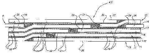
Figure 2 shows the section according to II-II in Figure 1.
The laminate shown in Figure 1 comprises three laminate parts 1, 2, 3 that are
fixed to one another by means of joins 4 and 5. Furthermore, it is possible to
differentiate
two regions in the laminate, i, e. a region 6 where there is a fill indicated
in its entirety by
8 between the layers of the laminate and a region without fill, or to put it
another way,
the standard laminate 7. At the location of the region 6 the laminate can be
fixed to
another laminate by means of strip 9.
It is known that at the location of the joins 4, 5 the standard laminate has a
somewhat greater thickness because the edges of the laminate overlap one
another there.
This means that at least one side of the laminate is not flat but is stepped
to some extent.
This is not desirable in some applications. In the case of an aircraft skin,
for example, it
is better if both sides of the laminate are completely flat. The frames 9 can
then be
attached to one side, the inside, while the other side nevertheless has
aerodynamic
properties because of the completely flat form thereof. Flatness of the
surface of the
laminate can also be desirable for other reasons. The fitting of underlying
structural

CA 02531536 2010-11-30
3
elements such as stiffeners, edge reinforcements for hatches or covers,
corners of door
openings and the like are mentioned as further examples.
According to the invention, the fill indicated in its entirety by 8 is
therefore
arranged in the region 6 at the location of the join to the frame 9. Said fill
is not needed
outside said region 6, that is to say in the region 7. The outside of the
laminate is
completely flat in that region, but it is not a problem if the inside of the
laminate is
stepped in this location. After all, a frame does not have to be attached to
the laminate at
that location.
As shown in Figure 2, the joins 4, 5 are implemented in a known manner with
overlapping edges of the metal layers 10, 11, 12 and 13. These metal layers
are bonded
to one another by means of fibre-reinforced bonding layers 14, 15, 16 and 17.
However,
the metal layers can also be bonded directly to one another by means of an
adhesive,
without fibre layers between them.
At the location of the joins 4, 5, each metal layer 10-13 forms two metal
layer
sections 18, 19, with respective overlapping edges 20 and 21, respectively.
These
overlapping edges are fixed to one another by means of an adhesive 22 for
transferring
stresses in the laminate by means of shear forces.
According to the invention, fills 8 in the form of metal layers 25, 24 in
combination with plastic bonding layers 28, 29 are arranged on either side of
the
overlapping edges 20, 21 of the metal layer 10. As shown in Figure 1, there
are several
fills, depending on the number of joins 4, 5. The fills have a thickness that
is equal to the
sum of the thickness of one of the metal layers 10-13 plus the thickness of
one of the
plastic bonding layers 14-17, such that on either side of the joins 4, 5 the
thickness of the
laminate is the same as that of the laminate at the location of the joins 4,
5. Both sides
26, 27 of the laminate are completely flat as a result.
By way of further explanation, and with reference to Figure 2, the laminate
may
include at least four metal layers (10-13) and a respective plastic bonding
layer (14-17)
between each adjacent pair of the metal layers. Each of the metal layers may
include a
pair of metal layer sections (18-19), where each pair of metal layer sections
has mutually
overlapping ends (20-21) whose opposing surfaces are bonded to one another. In
each
pair, one of the mutually overlapping ends is displaced in a thickness
direction of the
laminate (i.e., transverse to the metal layers) to overlap the other of the
mutually

CA 02531536 2010-11-30
4
overlapping ends in the respective pair so that, except for the displaced one
of the ends,
the pair of metal layer sections are extensions of one another. Further, the
mutually
overlapping ends of each pair of metal layer sections do not overlap the
mutually
overlapping ends of any other pair of metal layer sections such that at the
location of the
mutually overlapping ends the laminate has a uniform thickness (i.e., the
laminate has a
uniform thickness in the region of the four overlapping ends in Figure 2).
The laminate also includes a.fill (24, 25) that may be at least one further
metal
layer, where the fill is spaced from and does not overlap any of the mutually
overlapping
ends and has a thickness such that at the location of the fill the laminate
has a thickness
equal to the uniform thickness of the laminate at said mutually overlapping
ends (i.e., as
shown in Figure 2, the laminate has the same uniform thickness in the region
of the four
overlapping ends and in the region of the fill at the right and left ends of
Figure 2). That
is, the fill may be spaced laterally (left-right in Figure 2) from the
mutually overlapping
ends so as to avoid overlapping the mutually overlapping ends.

Representative Drawing
A single figure which represents the drawing illustrating the invention.
Administrative Status

2024-08-01:As part of the Next Generation Patents (NGP) transition, the Canadian Patents Database (CPD) now contains a more detailed Event History, which replicates the Event Log of our new back-office solution.

Please note that "Inactive:" events refers to events no longer in use in our new back-office solution.

For a clearer understanding of the status of the application/patent presented on this page, the site Disclaimer , as well as the definitions for Patent , Event History , Maintenance Fee  and Payment History  should be consulted.

Event History

Description Date
Time Limit for Reversal Expired 2019-07-08
Letter Sent 2018-07-09
Inactive: Late MF processed 2013-09-17
Letter Sent 2013-07-08
Grant by Issuance 2011-11-29
Inactive: Cover page published 2011-11-28
Pre-grant 2011-09-15
Inactive: Final fee received 2011-09-15
Notice of Allowance is Issued 2011-03-21
Letter Sent 2011-03-21
Notice of Allowance is Issued 2011-03-21
Inactive: Approved for allowance (AFA) 2011-03-16
Letter Sent 2011-02-10
Amendment Received - Voluntary Amendment 2010-11-30
Inactive: S.30(2) Rules - Examiner requisition 2010-06-01
Letter Sent 2009-08-14
Request for Examination Requirements Determined Compliant 2009-06-30
All Requirements for Examination Determined Compliant 2009-06-30
Request for Examination Received 2009-06-30
Letter Sent 2006-04-21
Inactive: Single transfer 2006-03-15
Inactive: Courtesy letter - Evidence 2006-03-07
Inactive: Cover page published 2006-03-06
Inactive: Notice - National entry - No RFE 2006-03-01
Application Received - PCT 2006-02-06
National Entry Requirements Determined Compliant 2006-01-05
Application Published (Open to Public Inspection) 2005-01-13

Abandonment History

There is no abandonment history.

Maintenance Fee

The last payment was received on 2011-06-27

Note : If the full payment has not been received on or before the date indicated, a further fee may be required which may be one of the following

  • the reinstatement fee;
  • the late payment fee; or
  • additional fee to reverse deemed expiry.

Please refer to the CIPO Patent Fees web page to see all current fee amounts.

Owners on Record

Note: Records showing the ownership history in alphabetical order.

Current Owners on Record
FOKKER AEROSTRUCTURES B.V.
Past Owners on Record
ABDOEL FAZIEL RAJABALI
WILLEM JAN NICOLAAS TER STEEG
Past Owners that do not appear in the "Owners on Record" listing will appear in other documentation within the application.
Documents

To view selected files, please enter reCAPTCHA code :


To view images, click a link in the Document Description column. To download the documents, select one or more checkboxes in the first column and then click the "Download Selected in PDF format (Zip Archive)" or the "Download Selected as Single PDF" button.

List of published and non-published patent-specific documents on the CPD .

If you have any difficulty accessing content, you can call the Client Service Centre at 1-866-997-1936 or send them an e-mail at CIPO Client Service Centre.


Document
Description 
Date
(yyyy-mm-dd) 
Number of pages   Size of Image (KB) 
Abstract 2006-01-05 1 68
Claims 2006-01-05 2 52
Description 2006-01-05 3 152
Drawings 2006-01-05 2 53
Representative drawing 2006-03-03 1 27
Cover Page 2006-03-06 1 57
Description 2010-11-30 4 200
Claims 2010-11-30 3 97
Cover Page 2011-10-25 1 57
Notice of National Entry 2006-03-01 1 193
Courtesy - Certificate of registration (related document(s)) 2006-04-21 1 128
Reminder - Request for Examination 2009-03-10 1 117
Acknowledgement of Request for Examination 2009-08-14 1 188
Commissioner's Notice - Application Found Allowable 2011-03-21 1 163
Maintenance Fee Notice 2013-08-19 1 171
Late Payment Acknowledgement 2013-09-17 1 163
Maintenance Fee Notice 2018-08-20 1 180
PCT 2006-01-05 2 66
Correspondence 2006-03-01 1 26
Fees 2008-07-02 1 36
Correspondence 2011-09-15 1 39