Note: Descriptions are shown in the official language in which they were submitted.
CA 02531588 2006-O1-06
WO 2005/026670 PCT/US2004/002639
AIR FOAM PiJMP WITH SHIFTING AIR PISTON
Ba~ound of the Invention
(1) Field of the Invention.
The present invention pertains to a manually operated liquid foaming
dispenser. Specifically, the invention pertains to a manually operated pump
that is
attached to the top of a bottle of liquid and that pumps and mixes both the
liquid and
air to create a foam from the liquid and dispense the foam. The dispenser
includes a
pump housing containing an air pump chamber and a liquid pump chamber, and a
pump plunger that is manually reciprocated in both the air pump chamber and
the
liquid pump chamber. An air piston and a liquid piston are mounted on the
plunger
and are reciprocated by the plunger in the respective air pump chamber and
liquid
pump chamber.
CA 02531588 2006-O1-06
WO 2005/026670 PCT/US2004/002639
2
(2) Description of the Related Art.
There are various different types of manually operated liquid dispensers that
pump liquid from containers attached to the dispensers and generate a foam
from the
liquid that is discharged from the dispensers. A familiar example of these
types of
foam generating liquid dispensers is the manually operated trigger sprayer.
Trigger
sprayers are designed to be comfortably held in one hand of a user with the
trigger of
the trigger sprayer being easily manipulated by the fingers of the user's
hand.
Pivoting movement of the trigger sprayer's trigger operates a liquid pump in
the
trigger sprayer. Operation of the pump draws liquid from a bottle container
connected
to the trigger sprayer and discharges the liquid in a spray pattern from a
discharge
nozzle of the trigger sprayer. The discharge nozzle of this type of trigger
sprayer
typically has an obstruction positioned in the path of the liquid sprayed from
the
trigger sprayer. The liquid spray hitting the obstruction mixes the liquid
spray with
the air of the exterior environment of the sprayer and thereby produces a foam
that is
discharged from the trigger sprayer.
The foaming liquid trigger sprayer of the type described above is well suited
for dispensing a foam produced from a liquid where the desired foaming of the
liquid
is marginal, for example in dispensing foaming liquid kitchen or bathroom
cleansers.
However, the typical foaming liquid trigger sprayer cannot produce a more
dense
foam, such as that of shaving cream.
To produce a more dense foam dispensed from a manually operated foaming
liquid dispenser requires that both the liquid and the air be pumped through
the
obstruction that produces the foam. Foaming liquid dispensers of this type
comprise a
pump housing containing an air pump chamber and a liquid pump chamber, and a
CA 02531588 2006-O1-06
WO 2005/026670 PCT/US2004/002639
3
pump plunger that is manually reciprocated in the pump housing. An air piston
is
mounted on the pump plunger and is received in the air pump chamber for
reciprocating movement, and a liquid piston is mounted on the pump plunger and
is
received in the liquid pump chamber for reciprocating movement. Movement of
the
pump plunger toward a retracted position into the pump housing causes the air
piston
to move into the air pump chamber and exert a force on the air in the chamber
and
causes the liquid piston to move into the liquid pump chamber and exert a
force on the
liquid in the chamber. A pair of valves control the flow of air and liquid
from the
respective air pump chamber and liquid pump chamber through a center discharge
passage of the pump plunger where the air and liquid is mixed to generate the
foam.
The foam is then discharged from the dispenser.
A spring of the foaming liquid dispenser causes the pump plunger to move
from its retracted position in the pump housing to an extended position where
the top
portion of the pump plunger projects outwardly from the top of the pump
housing.
This movement of the pump plunger causes the air piston and the liquid piston
to
move out of their respective air pump chamber and liquid pump chamber,
expanding
the interior volumes of the two chambers. This creates vacuums in the two pump
chambers that draw air into the air pump chamber interior volume and draw
liquid
into the liquid pump chamber interior volume. Valve assemblies are typically
employed in controlling the flow of air and liquid into the respective air
pump
chamber and liquid pump chamber as their interior volumes are increased by the
movement of the pump plunger. The valves allow air and liquid to enter the
respective air pump chamber and liquid pump chamber as the pump plunger moves
to
its extended position, and the valves close preventing air and liquid from
passing
CA 02531588 2006-O1-06
WO 2005/026670 PCT/US2004/002639
4
through the valves when the pump plunger is moved to its retracted position in
the
pump hauling.
A substantial number of manually operated foaming liquid dispensers are
manufactured to meet the needs of consumers. Reducing the manufacturing costs
of a
manually operated foaming liquid dispenser to only a small degree, for example
by
one penny or a fraction of a penny, significantly reduces the manufacturing
costs of
manually operated foaming liquid dispensers due to the significant number of
the
dispensers manufactured. Thus, a change in the design of a manually operated
foaming liquid dispenser that results in even a small reduction in its
manufacturing
costs could result in a significant benefit to the manufacturing of manually
operated
foaming liquid dispensers.
Summary of the Invention
The manually operated foaming liquid dispenser of the present invention has a
novel and simplified construction with a reduced number of component parts
from
that of prior art dispensers that pump both air and liquid in generating a
foam
discharged from the dispenser. The novel construction of the foaming liquid
dispenser eliminates a valve that controls the flow of air into the air pump
chamber of
the dispenser, thereby eliminating the cost of the valve and reducing the
manufacturing costs of the dispenser. In addition, the manually operated
foaming
liquid dispenser of the invention has a more simplified construction than that
of other
prior art foaming liquid dispensers. The more simplified construction of the
dispenser
also results in a reduction in manufacturing costs. In addition, the novel
construction
of the foaming liquid dispenser vents the interior of the air pump chamber to
the
CA 02531588 2006-O1-06
WO 2005/026670 PCT/US2004/002639
exterior environment of the dispenser immediately upon upward movement of the
pump plunger. This ensures that the air pump chamber is vented with air even
when
the user of the dispenser quickly reciprocates the pump plunger in the pump
housing
without allowing the pump plunger to return to its fully extended position
relative to
the pump housing.
The pump housing of the foaming liquid dispenser of the invention combines a
connector cap, an air pump chamber and a liquid pump chamber as one,
monolithic
piece. The liquid pump chamber, the air pump chamber, and the connector cap
have a
common center axis and are aligned axially in the pump housing. The
cylindrical
liquid pump chamber is positioned. at the bottom of the pump housing. An
opening in
the top of the liquid pump chamber communicates the interior volume of the
liquid
pump chamber with the cylindrical air pump chamber just above. The air pump
chamber also has an opening at its top that communicates the interior volume
of the
air pump chamber with the exterior environment of the dispenser through a top
opening of the pump housing. The connector cap surrounds the pump housing top
opening.
A dip tube is attached to the bottom of the pump housing and extends
downwardly from the liquid pump chamber. A liquid inlet control valve is
positioned
at the bottom of the liquid pump chamber. The liquid inlet control valve
controls a
flow of liquid through the dip tube and into the liquid pump chamber, and
prevents
the reverse flow.
The pump housing is connected to a bottle containing a liquid by first
inserting
the liquid pump chamber and the air pump chamber through a bottle neck opening
of
the bottle. The connector cap is attached to the exterior of the bottle neck
with the air
CA 02531588 2006-O1-06
WO 2005/026670 PCT/US2004/002639
6
pump chamber and liquid pump chamber positioned in the bottle. The dip tube
extends downwardly from the pump housing into the liquid contained in the
bottle to
a position adj acent the bottom of the bottle.
A pump plunger is assemble into the pump housing through the top opening of
the pump housing. The pump plunger has a tubular length with an interior
discharge
passage extending through the length of the pump plunger. A liquid piston is
assembled to the exterior of the pump plunger and is received in the liquid
pump
chamber for reciprocating movement therein. An air piston is also assembled to
the
exterior of the pump plunger and is received in the air pump chamber for
reciprocating movement therein.
A liquid outlet valve is assembled in the interior discharge passage of the
pump plunger adjacent the bottom of the plunger. The liquid outlet valve
controls the
flow of liquid out of the liquid pump chamber and into the plunger discharge
passage,
and prevents the reverse flow of liquid. An air outlet valve is also assembled
in the
interior discharge passage of the pump plunger at an intermediate position
along the
passage. The air outlet valve controls the flow of air out of the air pump
chamber and
into the plunger discharge passage, and prevents the reverse flow of air.
A spring is assembled between the pump housing and the pump plunger. The
spring biases the pump plunger to an extended position of the plunger relative
to the
pump housing where a top portion of the pump plunger projects outwardly from
the
top of the pump housing.
The pump plunger includes a dispenser head at the top of the pump plunger.
The dispenser head has a tubular center column and a spout that both function
as a
portion of the pump plunger interior discharge passage. The dispenser head
center
CA 02531588 2006-O1-06
WO 2005/026670 PCT/US2004/002639
7
column and spout conduct a foam produced by the dispenser, and the spout
discharges
the foam from the dispenser.
Manually depressing the pmnp plunger into the pump housing compresses the
spring and causes the air piston to move downwardly into the air pump chamber
decreasing the interior volume of the air pump chamber. The downward movement
of
the pump plunger also causes the liquid piston to move downwardly into the
liquid
pump chamber decreasing the interior volume of the liquid pump chamber. The
downward movement of the pump plunger causes the air piston to pressurize the
air in
the air pump chamber. The pressurized air causes the air outlet valve to
unseat, which
allows air from the air pump chamber to pass the air outlet valve and enter
the interior
discharge passage of the pump plunger. The downward movement of the pump
plunger also causes the liquid piston to exert a force on the liquid in the
liquid pump
chamber, which causes the liquid outlet valve to unseat. This results in the
liquid in
the liquid pump chamber being forced past the liquid outlet valve and into the
interior
discharge passage of the pump plunger. The air and liquid entering the
interior
passage of the pump plunger pass through a mixing element, which produces a
foam
from the air and liquid. The foam is forced upwardly through the pump plunger
interior discharge passage and is dispensed from the pump plunger.
On completion of the downward movement of the pump plunger into the
pump housing toward the retracted position of the pump plunger in the pump
housing,
the compressed spring causes the pump plunger to move out of the pump housing
toward its extended position relative to the pump housing. This in turn causes
the air
piston and liquid piston to move upwardly in the respective air pump chamber
and
liquid pump chamber, creating a vacuum pressure in each of these chambers. The
CA 02531588 2006-O1-06
WO 2005/026670 PCT/US2004/002639
vacuum pressure in the liquid pump chamber causes the liquid inlet valve to
unseat,
thereby drawing liquid upwardly from the dip tube into the liquid pump
chamber.
The novel construction of the manually operated foaming liquid dispenser of
the invention does not include a separate valve that opens in response to the
vacuum
created in the air pump chamber to allow air to vent into the air pump
chamber.
Instead, the air piston of the dispenser is constructed with a center hole
that functions
as a vent hole for the air pump chamber. The pump plunger extends through the
vent
hole of the air piston. This mounts the air piston on the pump plunger for
limited
axial movement of the air piston relative to the pump plunger.
The pump plunger is constructed with a first, upper projection on its exterior
and a plurality of second, lower projections on its exterior. The first
projection and
the plurality of second projections are on axially opposite sides of the
piston. The
axial spacing between the first projection and the plurality of second
projections
permits the air piston to move axially relative to the pmnp plunger between
the
projections. The exterior diameter dimension of the plunger between the first,
upper
projection and the second, lower projections is slightly smaller than the
interior
diameter dimension of the air piston vent hole. This provides a radial spacing
between the exterior surface of the pump plunger and the interior surface of
the air
piston vent hole. This radial spacing defines a vent air flow path between the
pump
plunger and the air piston.
The first, upper projection is designed as an annular stopper. When the pump
plunger moves downward relative to the air piston, the annular stopper engages
in the
air piston vent hole and seals the hole. The plurality of second, lower
projections are
spatially arranged around the exterior of the plunger. Each of the plurality
of second,
CA 02531588 2006-O1-06
WO 2005/026670 PCT/US2004/002639
9
lower projections are dimensioned to engage in the vent hole of the air piston
to stop
the upward movement of the pump plunger relative to the air piston. However,
because the plurality of second, lower projections are spatially arranged
around the
pump plunger, when the second, lower projections engage in the vent hole of
the air
pump piston they do not block the vent air flow path between the pump plunger
and
the air piston.
Thus, when the pump plunger is pushed manually downwardly into the pump
housing, the pump plunger first, upper projection engages in and seals closed
the vent
hole of the air piston. This allows the air piston to compress the air in the
air pump
chamber as the pump plunger pushes the air piston downwardly into the air pump
chamber. When the pump plunger is moved upwardly by the spring toward its
extended position relative to the pump housing, the limited axial movement of
the air
piston relative to the pump plunger provided by the axially spaced first and
second
projections causes the first, upper projection to move out of the vent hole of
the air
piston. This opens the vent air flow path between the pump plunger and the
interior
surface of the air piston surrounding the vent hole. Thus, venting air from
the exterior
environment of the dispenser is allowed to pass through the vent air flow path
between the pump plunger and the air piston as the air piston is moved
upwardly
through the air pump chamber by the pump plunger. This vents the interior
volume of
the air pump chamber without requiring an additional valve to control the
venting of
the air pump chamber.
Because the first and second projections on the pump plunger allow the air
piston to move axially to a limited extent relative to the pump plunger, the
air piston
does not begin pressurizing air in the air pump chamber on the initial
downward
CA 02531588 2006-O1-06
WO 2005/026670 PCT/US2004/002639
movement of the pump plunger into the pump housing. To ensure that both air
and
liquid are pumped into the pump plunger interior discharge passage at the same
time,
the liquid piston is also mounted on the pump plunger for limited axial
movement of
the liquid piston relative to the pump plunger. This allows the pump plunger
to move
downwardly into the pump housing the short distance required for the first,
upper
projection to seat in the vent hole of the air piston before the pump plunger
begins
pushing the liquid piston downwardly through the liquid pump chamber. The
limited
axial movement of the liquid piston relative to the pump plunger enables both
the air
piston and the liquid piston to begin their pumping operations from the
respective air
and liquid pump chambers at approximately the same time.
Thus, the foaming liquid dispenser of the invention enables mixing of air and
liquid pumped into the dispenser discharge passage to generate a thick foam
discharged by the dispenser while eliminating a valve required by prior art
dispensers
to vent air to the air pump chamber. The elimination of the valve results in a
reduction of manufacturing costs. The simplified construction of the foaming
dispenser with its reduced number of component parts also reduces the
manufacturing
cost of the dispenser. In addition, the assembly of the air piston on the pump
plunger
that enables limited axial movement between the air piston and the pump
plunger
vents the interior of the air pump chamber promptly on upward movement of the
pump plunger. This ensures that the air pump chamber is vented with air even
when a
user of the dispenser quickly reciprocates the pump plunger in the pump
housing
without allowing the pump plunger to return to its fully extended position
relative to
the pump housing.
CA 02531588 2006-O1-06
WO 2005/026670 PCT/US2004/002639
Description of the Drawings
Further features of the invention are set forth in the following detailed
description of the preferred embodiment of the invention and in the drawing
figures
wherein:
Figure 1 is a front perspective view of the manually operated, foaming liquid
dispenser of the invention attached to the top of a bottle container;
Figure 2 is a side, sectioned view of the dispenser along the line 2-2 of
Figure
l, with the pump plunger in its fully extended position relative to the pump
housing and the bottle container;
Figure 3 is a partial, enlarged view of the relative positions of the air
piston
and pump plunger shown in Figure 2;
Figure 4 is a side, sectioned view of the dispenser with the pump plunger in
its
fully retracted position relative to the pump housing and the bottle
container;
and,
Figure 5 is a partial, enlarged view of the relative positions of the air
piston
and the pump plunger shown in Figure 4.
Detailed Descr~tion of the Preferred Embodiment
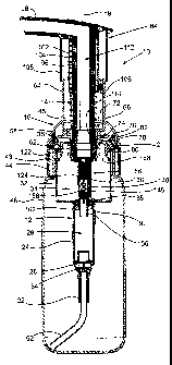
The foaming liquid dispenser 10 of the present invention is similar to the
types
of dispensers known in the prior art as lotion dispensers. These types of
dispensers
are typically operated by connecting the dispenser to the neck of a bottle
container
containing a liquid to be dispensed and by orienting the dispenser and the
container
vertically upright. In the description of the foaming liquid dispenser of the
invention
CA 02531588 2006-O1-06
WO 2005/026670 PCT/US2004/002639
12
to follow, the terms "top" and "bottom", "upper" and "lower", or similar
related terms
will be used to describe the component parts of the dispenser and their
relative
positions. These terms are only used because the dispenser is typically
oriented
vertically upright when using the dispenser. The terms should not be
interpreted as
limiting.
The liquid foaming dispenser 10 shown in Figures 1, 2, and 4 is basically
comprised of a pump housing 12, a pump plunger 14 and a snap ring 16 that
connects
the pump housing and pump plunger together. The materials employed in
constructing the component parts of the dispenser are the same as those
typically used
in the industry, usually plastics except for a metal coil spring employed on
the pump
plunger.
The pump housing 12 basically combines four cylindrical sections of the
pump housing and a connector cap as one, monolithic piece. The cylindrical
sections
of the housing and the connector cap have a common center axis 1 ~ and are
axially
aligned in the pump housing.
The cylindrical sections include a cylindrical dip tube connector 22 provided
at the bottom of the pump housing. A cylindrical liquid pump chamber 24 is
provided
as the second cylindrical section of the pump housing just above the dip tube
connector 22. A valve seat surface 26 is positioned at the bottom of the
liquid pump
chamber 24. The interior volume 2~ of the liquid pump chamber 24 communicates
with the interior of the dip tube connector 22 through the valve seat 26. The
liquid
pump chamber 24 is open at its top end.
The third cylindrical section of the pump housing 12 is a cyliildrical air
pump
chamber 32 positioned just above the liquid pump chamber 24. The air pump
CA 02531588 2006-O1-06
WO 2005/026670 PCT/US2004/002639
13
chamber 32 has an interior volume 34 that communicates with the liquid pump
chamber interior volume 28 through the top opening of the liquid pump chamber
24.
The air pump chamber 32 is open at its top end.
A cylindrical sleeve 36 forms the fourth cylindrical section of the pump
housing 12. The sleeve 36 extends upwardly from the top of the air pump
chamber
32. Several bottle container vent holes 42 pass through the sleeve 36. The
cylindrical
sleeve 36 is also open at its top.
The cylindrical connector cap 44 is attached to the bottom of the sleeve 36.
As seen in Figures 2 and 4, the connector cap 44 extends downwardly over and
is
spaced radially outwardly from the air pump chamber 32. An interior surface of
the
connector cap 44 is provided with a mechanical connector, for example a
bayonet
type connector or a screw-threaded connector. The particular connector
employed on
the connector cap 44 will be complementary to a connector on a bottle
container with
which the liquid foaming dispenser 10 is used.
As stated earlier, the dip tube connector 22, the liquid pump chamber 24, the
air pump chamber 32, the cylindrical sleeve 36 and the connector cap 34 of the
pump
housing 12 are all formed as one, monolithic piece. Forming all of these
component
pacts as one piece reduces the total number of separate component parts of the
liquid
foaming dispenser 10. This reduction in parts also results in a cost savings
in
manufacturing the dispenser.
The pump housing 12 is shown mounted on a bottle container 46 in Figures 1,
2, and 4. The bottle container 46 shown in the drawing figures is only one
example of
a bottle container with which the liquid foaming dispenser 10 may be used. In
removably attaching the pump housing 12 to the bottle container 46, the bottle
CA 02531588 2006-O1-06
WO 2005/026670 PCT/US2004/002639
14
container is provided with a neck 48 having a mechanical connector that is
complementary to the mechanical connector of the pump housing connector cap
44.
With the pump housing 12 removably attached to the bottle container 46 by the
connector cap 44, the liquid pump chamber 24 and the air pump chamber 32 of
the
pump housing 12 are entirely contained inside the bottle container 46. This
reduces
the overall size of the liquid foaming dispenser 10 and bottle container 46.
A dip tube 52 is attached to the dip tube connector 22 at the bottom of the
pump housing. The dip tube 52 extends downwardly from the pump housing 12 into
the liquid of the container to a position adjacent the bottom of the bottle
container 46.
A liquid inlet control valve 54 is positioned at the bottom of the liquid pump
chamber 24. The liquid inlet control valve 54 is a flexible, resilient disk
check valve
that seats against the valve seat surface 26 at the bottom of the liquid pump
chamber
24. The liquid inlet control valve 54 is responsive to a vacuum pressure
created in the
interior volume 28 of the liquid pump chamber 24. The valve 54 controls a flow
of
liquid from the bottle container 46 through the dip tube 52 and into the
liquid pump
chamber interior volume 28, and prevents the reverse flow of liquid.
The snap ring 16 is assembled to the top of the pump housing 12. The snap
ring 16 has a top cover 58 and a cylindrical outer wall 62 that fits snug
around the
cylindrical sleeve 36 of the pump housing 12. A cylindrical tube 64 extends
upwardly
from the snap ring cover 58. A lock tab 65 projects inwardly from an interior
surface
of the tube 64. The upper portion of the tube 64 above the snap ring cover 58
provides an aesthetic cover for an upper portion of the pump plunger 14 and a
spring
mounted on the pump plunger that is yet to be described. A portion of the tube
64
extends below the snap ring cover 58 to a circular bottom wall 66 of the snap
ring.
CA 02531588 2006-O1-06
WO 2005/026670 PCT/US2004/002639
The snap ring bottom wall 66 has an opening 68 at its center to accommodate
the
pump plunger 14, as will be described. A bottle vent hole 72 also extends
through the
snap ring bottom wall 66. A cylindrical plunger tube 74 extends downwardly
from
the underside of the snap ring bottom wall 66. The plunger tube 74 limits the
upward
movement of the pump plunger 14 relative to the pump housing 12 to the
extended
position of the pump plunger shown in Figures 1 and 2.
A cylindrical vent separator 76 is assembled onto the exterior of the snap
ring
plunger tube 74 and into the interior of the pump housing cylindrical sleeve
36. The
vent separator 76 is formed as a flat ring with a downwardly extending inner
cylindrical wall 78, a downwardly extending intermediate cylindrical wall 80,
and a
downwardly extending outer cylindrical wall 82. The inner cylindrical wall 78
of the
vent separator 76 extends downwardly from the inner edge of the separator and
engages tightly against the outer surface of the snap ring plunger tube 74.
The
intermediate wall 80 extends over the interior surface of the air pump chamber
32.
The outer cylindrical wall 82 extends downwardly from an outer peripheral edge
of
the vent separator 76 over the interior surface of the pump housing
cylindrical sleeve
36. A gap is provided between the vent separator outer wall 82 and the pump
housing
sleeve 36. This gap functions as a portion of an air venting flow path from
the
exterior environment of the dispenser, between the vent separator outer wall
82 and
the sleeve 36, and through the pump housing bottle vent holes 42.
The pump plunger 14 is basically comprised of an upper dispenser head 84, a
lower piston rod 86, an air piston 88 mounted on the piston rod 86, and a
liquid piston
92 mounted on the piston rod 86.
CA 02531588 2006-O1-06
WO 2005/026670 PCT/US2004/002639
16
The upper dispenser head 84 has a tubular center column 96 that extends
downwardly through the dispenser head. The column 96 is open at its bottom. An
interior bore of the column communicates with a discharge spout 98 of the
dispenser
head at the top of the column.
A metal coil spring 102 is mounted over the center column 96. The spring
engages against the snap ring bottom wall 66 at the bottom of the spring and
engages
against the dispenser head 84 at the top of the spring. The spring 102 urges
the
dispenser head and the pump plunger 14 upwardly to its extended position shown
in
Figures l and 2.
An inner cylindrical wall 104 of the dispenser head 84 extends downwardly
over the spring. The inner cylindrical wall 104 has a lock tab 106 that
projects
outwardly from the wall. The dispenser head 84 can be pressed downwardly
against
the bias of the spring 102 and rotated so that the dispenser head lock tab 106
engages
underneath the snap ring lock tab 65 to hold the dispenser head 84 in its
downward,
retracted position relative to the dispenser 10.
The dispenser head also has an outer cylindrical wall 108. The outer wall 108
telescopes over the snap ring tube 64. The overlapping of the outer wall 108
and the
snap ring tube 64 prevents liquid from entering into the pump plunger 14 and
also
gives the dispenser an aesthetically pleasing appearance.
The interior bore of the dispenser head center column 96 and an interior bore
of the dispenser head spout 98 define a portion of an interior discharge
passage 112 of
the pump plunger that extends through the length of the dispenser head 84. A
foam
producing obstruction is positioned in the interior discharge passage 112
adjacent the
bottom of the passage. The obstruction is comprised of a cylindrical hub 114
having
CA 02531588 2006-O1-06
WO 2005/026670 PCT/US2004/002639
17
mesh screens 116 covering over the opposite open ends of the hub. Air and
liquid
passing through the two mesh screens 116 of the hub 114 produce a foam.
The pump plunger piston rod 86 is tubular and an upper end of the piston rod
is attached to a lower end of the dispenser head center column 96. The tubular
piston
rod 86 has an interior bore that extends through the length of the rod and
communicates with the interior bore of he dispenser head center column 96. The
interior bores of the piston rod 86; the dispenser head center column 96 and
the spout
98 define the length of the interior discharge passage 112 extending through
the pump
plunger 14. The portion of the discharge passage 112 extending through the
piston
rod 86 and the dispenser head center column 96 has a center axis that is
coaxial with
the center axis 18 of the pump housing 12.
The piston rod 86 has a cylindrical, upper air piston portion 122 and a
cylindrical, lower liquid piston portion 124. The air piston portion 122 has a
cylindrical interior surface that extends downwardly through the piston rod to
an
annular bottom wall 126 that joins the air piston portion 122 to the liquid
piston
portion 124 of the piston rod. A pair of diametrically opposed valve openings
128
(only one of which is visible in Figure 5) extend through the annular bottom
wall 126.
The liquid piston portion 124 of the piston rod also has a cylindrical
interior surface
that extends downwardly from the annular bottom wall 126 to the bottom end of
the
piston rod 86.
The exterior surface of the air piston portion 122 of the piston rod is
provided
with a first, upper proj ection 132 and a plurality of second, lower proj
ections 134.
The first proj ection 132 is an annular proj ection that extends completely
around the
air piston portion 122 of the piston rod. As best seen in Figures 3 and 5, the
first
CA 02531588 2006-O1-06
WO 2005/026670 PCT/US2004/002639
1$
projection 132 tapers radially outwardly as it extends axially upwardly over
the
exterior surface of the piston rod. Each of the plurality of second
projections 134 is
formed as a narrow ridge that projects radially outwardly from the piston rod
air
piston portion 122 as it extends axially over the exterior surface of the rod.
The
second projections 134 are spatially arranged around the exterior surface of
the piston
rod air piston portion 122.
An axial rib 136 is provided on the exterior surface of the piston rod liquid
piston portion 124. The rib 136 extends downwardly over the exterior surface
of the
liquid piston portion 124 but stops short of the bottom end of the piston rod,
forming a
radial shoulder 138 that projects outwardly from the liquid piston portion 124
of the
rod.
A one-piece valve assembly including a tubular sleeve valve 142, a center
stem 144, a resilient spring 146 and a plug check valve 148 is assembled into
the
interior of the dispenser piston rod 86. The tubular sleeve valve 142 proj
ects
upwardly from an annular bottom wall 152 of the valve assembly. The bottom
wall
152 has an opening at its center that communicates with the interior of the
liquid
piston portion 124 of the piston rod and forms a portion of the interior
discharge
passage 112 extending through the pump plunger. The outer periphery of the
bottom
wall 152 engages against the interior surface of the air piston portion 122 of
the piston
rod and secures the valve assembly in place. A pair of diametrically opposed
notches
154 pass through the bottom wall 152 in positions that coincide with the valve
openings 128 of the piston rod annular wall 126. The resilient sleeve 142 of
the valve
assembly extends upwardly from the bottom wall 152 inside the pair of notches
154
CA 02531588 2006-O1-06
WO 2005/026670 PCT/US2004/002639
19
and engages against the interior surface of the dispenser head center column
96 in a
sealing engagement.
The center stem 144 of the valve assembly has a +-shaped cross section. The
stem 144 engages against the interior surface of the liquid piston portion 124
of the
piston rod to securely hold the valve assembly in place while allowing liquid
to flow
axially along the center stem 144. The resilient spring 146 extends downwardly
from
the bottom end of the stem 144 and biases the plug check valve 148 downwardly.
A valve seat plug 156 is inserted into the opening at the bottom of the liquid
piston portion 124 of the piston rod. The valve seat plug 156 has a seating
surface
158 against which the plug check valve 148 engages. An annular ring 162 on the
valve seat plug 156 engages against the bottom of the liquid piston portion
124 of the
piston rod to insure that the valve seat plug is properly positioned. The plug
check
valve 148 engaging against the seating surface 158 of the valve seat plug 156
functions as a liquid outlet valve of the liquid pump chamber 124.
The liquid piston 92 is mounted on the bottom end of the liquid piston portion
124 of the piston rod between the annular ring 162 of the valve seat plug 156
and the
radial shoulder 138 of the piston rod axial rib 136. As best seen in Figure 4,
an axial
spacing between the valve seat plug annular ring 162 and the shoulder 138 of
the axial
rib 136 allows the liquid piston 192 to move axially over the pump plunger 14
for a
short distance. The liquid piston 192 is positioned in the liquid pump chamber
24 in a
sliding sealing engagement of the liquid piston against the interior surface
of the
liquid pump chamber. The engagement of the liquid piston 92 against the
interior
surface of the liquid pump chamber 24 causes the liquid piston to move
upwardly
relative to the pump plunger 14 when the plunger is moved downwardly until the
CA 02531588 2006-O1-06
WO 2005/026670 PCT/US2004/002639
liquid piston 92 engages against the shoulder 138 of the axial rib 136. The
liquid
piston 92 also moves downwardly relative to the pump plunger 14 when the pump
plunger is moved upwardly until the liquid piston 92 engages with the annular
ring
162 of the valve seat plug 156.
The air piston 88 is formed as a flat ring 164 with a downwardly extending
imler cylindrical wall 166 at an inner peripheral edge of the ring and a
downwardly
extending outer cylindrical wall 168 at an outer peripheral edge of the ring.
The air
piston inner cylindrical wall 166 has an interior surface 172 that is spaced a
small
distance radially outwardly from the exterior surface of the piston rod air
piston
portion 122. This creates a small annular gap between the exterior surface of
the
piston rod air piston portion 122 and the interior surface 172 of the air
piston inner
cylindrical wall 166 that functions as an air vent flow path. The radial
spacing
between the exterior surface of the piston rod air piston portion 122 and
interior
surface 172 of the air piston inner cylindrical wall 166 defines a vent
opening or a
vent hole through the air piston 88 through which the pump plunger 14 extends.
The
radial spacing between the exterior surface of the piston rod air piston
portion 122 and
the air piston inner cylindrical wall interior surface 172 enables the air
piston 88 to
move axially to a limited extent relative to the pump plunger 14. The extent
of axial
movement of the air piston 88 on the pump plunger 14 is limited by the first,
upper
projection 132 of the pump plunger above the air piston, and the second, lower
projections 134 below the air piston.
The air piston flat ring 164 extends radially outwardly from the air piston
inner cylindrical wall 66 to the air piston outer cylindrical wall 168 to
position the
outer cylindrical wall where it will engage in a sliding, sealing engagement
with the
CA 02531588 2006-O1-06
WO 2005/026670 PCT/US2004/002639
21
interior surface of the air pump chamber 32. The sliding, sealing engagement
of the
air piston outer cylindrical wall 168 with the air pump chamber 32 exerts a
sufficient
frictional resistance to movement of the air piston 88 relative to the air
pump chamber
32 to cause the air piston 88 to move relative to the pump plunger 14 when the
pump
plunger is moved upwardly and downwardly in the pump housing 12.
The first, upper projection 132 of the pump plunger piston rod 86 is designed
as an annular stopper. The upper projection 132 has an outer diameter
dimension that
is slightly larger than the inner diameter dimension of the air piston inner
cylindrical
wall interior surface 172. When the pump plunger 14 moves downward relative to
the
air piston 88, the asmular stopper formed by the upper projection 132 engages
in the
air piston vent hole formed by the inner cylindrical wall interior surface 172
and seals
the hole. Each of the plurality of second, lower projections 132 on the piston
rod 86
are dimensioned to engage in the vent hole of the air piston defined by the
inner
cylindrical wall interior surface 172. The plurality of second, lower
projections 134
stop the upward movement of the pump plunger 14 relative to the air piston 88.
However, because the plurality of second, lower projections 134 are spatially
arranged around the pump plunger 14, when the second, lower projections 134
engage
in the vent hole of the air piston defined by the inner cylindrical wall
interior surface
172, they do not block the vent air flow path between the exterior surface of
the piston
rod air pistorx portion 122 and the interior surface 172 of the air piston
inner
cylindrical wall 166.
Thus, when the pump plunger 14 is pushed manually downwardly into the
pump housing 12, the pump plunger first, upper projection 132 engages in and
seals
closed the vent hole of the air piston defined by the interior surface 172 of
the air
CA 02531588 2006-O1-06
WO 2005/026670 PCT/US2004/002639
22
piston inner cylindrical wall 166. This allows the air piston 88 to compress
the air in
the air pump chamber 32 as the pump plunger 14 pushes the air piston 88
downwardly
into the air pump chamber 32. When the pump plunger 14 is moved upwardly by
the
spring 102 toward its extended position relative to the pump housing 112, the
limited
axial movement of the air piston 88 relative to the pump plunger 14 provided
by the
axially spaced first projection 132 and second projections 134 causes the
first, upper
projection 132 to move out of the vent hole of the air piston defined by the
inner
surface 172 of the air piston inner cylindrical wall 66. This opens the vent
air flow
path between the exterior surface of the piston rod air piston portion 122 and
the air
piston inner cylindrical wall interior surface 172. Thus, venting air from the
exterior
environment of the dispenser 10 is allowed to pass through the telescoping
coupling
of the dispenser head outer cylindrical wall 108 and the snap ring tube 64,
and
between the exterior surfaces of the pump plunger upper dispenser head 84 and
lower
piston rod 86 and the interior surface of the snap ring plunger tube 74, to
the vent air
flow path between the exterior surface of the piston rod air piston portion
122 and the
air piston inner cylindrical wall interior surface 172 as the air piston 88 is
moved
upwardly through the air pump chamber 32 by the pump plunger 14. This vents
the
interior volume 34 of the air pump chamber 32 without requiring an additional
valve
to control the venting of the air pump chamber.
Because the first 132 and second projections 134 on the pump plunger 14
allow the air piston 88 to move axially to a limited extent relative to the
pump
plunger, the air piston 88 does not begin pressurizing air in the air pump
chamber 32
on the initial downward movement of the pump plunger 14 into the pump housing
12.
To ensure that both air and liquid are pumped into the pump plunger interior
CA 02531588 2006-O1-06
WO 2005/026670 PCT/US2004/002639
23
discharge passage 112 at the same time, the liquid piston 92 has been mounted
on the
piston rod liquid piston portion 124 for a limited axial movement of the
liquid piston
relative to the pump plunger. This allows the pump plunger 14 to move
downwardly
into the pump housing 12 a short distance required for the first, upper
projection 132
to seat in sealing engagement in the vent hole of the air piston defined by
the air
piston inner cylindrical wall interior surface 172 before the pump plunger
begins
pushing the liquid piston 92 downwardly through the liquid pump chamber 24.
The
limited axial movement of the liquid piston 92 relative to the pump plunger 14
enables both the air piston 88 and the liquid piston 92 to begin their pumping
operations from the respective air pump chamber 32 and liquid pump chamber 24
at
approximately the same time.
Thus, the foaming liquid dispenser of the invention enables mixing of air and
liquid pumped into the dispenser discharge passage to generate a thick foam
discharged by the dispenser while eliminating a valve required by prior art
dispensers
to vent air to the air pump chamber. The elimination of the air vent valve
results in a
reduction of manufacturing costs. The simplified construction of the foaming
dispenser also combines several different component parts of prior art foaming
dispensers into one piece. This simplified construction also reduces the
manufacturing cost of the dispenser. In addition, the assembly of the air
piston on the
pump plunger that enables limited axial movement between the air piston and
the
pump plunger vents the interior of the air pump chamber promptly on upward
movement of the pump plunger. This ensures that the air pump chamber is vented
with air even when a user of the dispenser quickly reciprocates the pump
plunger in
CA 02531588 2006-O1-06
WO 2005/026670 PCT/US2004/002639
24
the pwnp housing without allowing the pump plunger to return to its fully
extended
position relative to the pump housing.
Although the manually operated foaming liquid dispenser of the invention has
been described above by reference to a single embodiment, it should be
understood
that modifications and variations could be made to the dispenser without
departing
from the intended scope of the invention defined by the following claims.