Note: Descriptions are shown in the official language in which they were submitted.
CA 02531979 2006-O1-05
Attorney Docket No.: 100041-41240
MODULAR STORAGE SYSTEM
The present invention is directed to a modular storage system, and more
particularly to a
modular storage system for use with school and office supplies.
BACKGROUND
School and office supplies, such as notebooks, binders, pens, pencils,
staplers, scissors,
binding clips, loose leaf papers, rubber bands, correction tape, correction
fluid, drawing guides,
letter openers, highlighters, erasers, calculators and the like are often
desired to be stored in a
storage unit. However, the storage needs for any individual user will vary
from user to user and
thus a single storage unit of fixed capacity may not meet the needs of
different users. In
addition, a user may often desire to utilize the storage unit in a portable
manner, or desire to
modify the configuration of the storage unit. Accordingly, there is a need for
a storage unit
which can be assembled to meet the needs of individual users, and which
provides portable
storage units.
SUMMARY
In one embodiment, the present invention is a modular storage system which can
be
assembled in various configurations, and which provides individual modular
units which can be
separated from each other and used as a standalone component. More
particularly, in one
embodiment the invention is a modular system comprising a plurality of modular
units, each
modular unit being sized to be hand carned and configured to store school and
office supplies
therein. Each modular unit has a plurality of generally flat outer surfaces.
Each modular unit is
configured to be coupled to another modular unit along facing, parallel outer
surfaces thereof
when a facing outer surface of one of the modular units is moved towards the
facing outer
surface of the other modular unit in a direction generally perpendicular to
the facing outer
surfaces until the modular units contact each other.
BRIEF DESCRIPTION OF THE DRAWINGS
Fig. 1 is a perspective view of one embodiment of the modular storage system
of the
present invention;
1
,~ CA 02531979 2006-O1-05
Attorney Docket No.: 100041-41240
Fig. 2 is a front view of the modular storage system of Fig. l;
Fig. 3 is another perspective view of the modular storage system of Fig. 1;
Fig. 4 is a perspective view of the modular storage system of Fig. 3, with the
various
drawers moved to their open positions;
Fig. 5 is an exploded view of the modular storage system of Fig. 3;
Fig. 6 is a bottom view of the modular storage system of Fig. 5;
Fig. 7 is a perspective view of the system of Fig. 1 rearranged in a different
configuration;
Fig. 8 is a perspective view of an alternate embodiment of the modular storage
system of
the present invention;
Fig. 9 is a perspective view of another alternate embodiment of the modular
storage
system of the present invention;
Fig. 10 is an exploded view of the modular storage system of Fig. 9;
Fig. 11 is an exploded view of the modular storage system of Fig. 9, showing
the
locations of various magnetized or attachment surfaces; and
Fig. 12 is a side cross section taken along line 12-12 of Fig: 11.
DETAILED DESCRIPTION
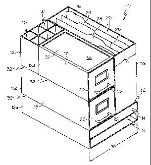
As shown in Fig. 1, in one embodiment the modular system of the present
invention,
generally designated 10, includes a plurality of modules or modular units 12
which are directly
coupled together to form the modular system 10. Each modular unit 12 may have
various sizes
and shapes, and may be configured to be hand carried and to store school and
office supplies
therein. The modular system 10 may be configured such that when the modular
units 12 are
assembled, the modular system 10 forms a generally rectangular prism.
As best shown in Fig. 5, in the illustrated embodiment the modular system 10
includes
five modular units 12. However, the modular system 10 may have any of a wide
variety of
numbers of modular units 12, and the modular units 12 can vary from those
shown herein. In the
illustrated embodiment, the modular system 10 includes a storage shelf modular
unit 12a, a
storage slot modular unit 12b, a pair of drawer modular units 12c, 12d, and a
hanging file folder
modular unit 12e. The storage shelf modular unit 12a includes a pair of
vertically spaced shelves
14 extending substantially the entire length and width of the modular unit 12a
such that the
2
CA 02531979 2006-O1-05
Attorney Docket No.: 100041-41240
storage shelf modular unit 12a can receive loose leaf papers, notebooks,
binders and the like
therein. The storage shelf modular unit 12a may be sized to relatively closely
receive a notebook
of 8 '/2 x 11 sheets of paper therein.
The storage slot modular unit 12b includes a plurality of generally vertically-
extending
cavities 16 in which various school and office supplies such as pens, pencils,
staplers, scissors;
letter openers, highlighters, erasers and the like may be stored.
Each of the drawer modular units 12c, 12d includes an outer drawer casing 18,
as well as
a drawer 20 that is movably, slidably, or rollably received in the outer
drawer casing 18. Each
drawer 20 has a pull handle 22 to aid in opening and closing the drawer 20.
Fig. 4 illustrates the
drawers 20 of the drawer modular units 12c, 12d moved at least partially to
their open positions.
Each drawer 20 defines an inner cavity 24 in which papers and various school
and office supply
products can be stored.
Drawer modular unit 12d has a lesser depth than the drawer modular unit 12c.
In
particular, drawer modular unit 12d has a depth that is less than the drawer
modular unit 12c by a
1 S distance about equal to the depth of the storage slot modular unit 12b
such that when the drawer
modular unit 12d and storage slot modular unit 12b are placed adj acent to
each other, their
combined depth is substantially equal to the depth of the drawer modular unit
12c.
The hanging file folder modular unit 12e includes a main inner cavity 26 in
which a
plurality of folders, including, but not limited to, hanging file folders 28,
may be received for
- storing and organizing various papers and the like.
The modular system 10 may have various sizes and dimensions. For example, in
one
embodiment the system 10 may have a height of about 13.5 inches, a width
(i.e., along
dimension w1 of Fig. 1) of about 9.25 inches, and a depth of about 12.25
inches. The modular
system 10 may define a volume of less than abut 8600 cubic inches, or less
than about 1296
cubic inches and may have a weight of less than about 30 lbs, or less than
about 15 lbs, or less
than about 10 lbs. Each modular unit 12 may be a generally rectangular prism
defining a volume
of less than about 1720 cubic inches, or less than about 500 cubic inches, and
may have a weight
of less than about 10 lbs, or less than about 5 lbs, or less than about 3 lbs.
As noted above, each of the modular units 12 may be shaped as a generally
rectangular
prism having a plurality (i.e., six) of generally flat, planar outer surfaces
and a storage cavity
therein. At least one or perhaps more of the outer surfaces of each modular
units 12 may include
3
CA 02531979 2006-O1-05
Attorney Docket No:: 100041-41240
an attachment structure or fastening means 32 forming or located adjacent to
one of the outer
surfaces for coupling each modular unit 12 to another modular unit 12. For
example, as best
shown in Fig. 6, each of the modular units 12 may include a foot or protrusion
34 extending
outwardly from a bottom surface thereof.
Each foot 34 may be generally rectangular in top view; and may cover at least
about SO%,
or at least about 80%, or at least about 90% of the surface area of the
associated outer surface of
the modular unit 12. Each foot 34 may have a height of about 0.15 inches, or
less than about 0.5
inches, or less than about 0.25 inches. Each foot 34 may have a height that is
less than about
10%, or less than about 5% of the height of the associated modular unit 12.
As best shown in Fig 5, some or all of the modular units 12 may include a
recess 36
forming or located adjacent to an upper outer surface thereof. Each recess 36
can be considered
to be part of the attachment structure or fastening means 32. In the
illustrated embodiment, the
storage slot modular unit 12b and drawer modular units 12c, 12d each include a
recess 36 on an
upper surface thereof. Each recess 36 may be sized to generally closely
receive the foot or feet
34 of other modular units 12 therein.
Each recess 36 may be generally rectangular in top view, and may cover at
least about
50%, or at least about 80%, or at least about 90% of the surface area of the
associated outer
surface of the modular unit 12. Each recess 36 may have a depth of about 0.15
inches, or less
than about 0.5 inches, or less than about 0.25 inches. Each recess 36 may have
a depth that is
less than about 10%, or less than about 5% of the height of the associated
modular unit 12.
The feet 34 and recesses 36 of the modular units 12 can cooperate to couple
the modular
units 12 together to form an assembled modular system 10. For example, the
feet 34 of the
hanging file folder modular unit 12e and the drawer modulax unit 12c can be
received in the
recess 36 of the storage shelf modular unit 12a such that the hanging file
folder modular unit 12e
and drawer modular unit 12c are thereby coupled to the storage shelf modular
unit 12a.
Similarly, the feet 34 of the drawer modular unit 12d and storage slot modular
unit 12b can be
received in the recess 36 of the drawer modular unit 12c such that the drawer
modular unit 12d
and storage slot modular unit 12b are thereby coupled to the drawer modular
unit 12c. In this
manner, each of the modular units 12 can be coupled together to form the
modular unit system
10 of Fig. 1. Fig. 2 illustrates the modular unit system 10 wherein each foot
34 of the upper
modular units 12b, 12c, 12d, 12e is received in a corresponding recess 36.
4
CA 02531979 2006-O1-05
Attorney Docket No.: 100041-41240
In this manner each modular unit 12 can be coupled together. For example, with
reference to Fig: 5, when the foot 34 of the hanging file modular unit 12e is
to be received in the
recess 36 of the storage slot module 12a, the hanging file modular unit 12e is
arranged and
positioned such that its bottom surface 30a faces and is located above the top
surface 30b of the
storage slot module 12a. More particularly the bottom surface 30a of the
hanging file modular
unit 12e and the top surface 30b of the storage slot module 12a (i.e: the
facing or engaging or
coupling surfaces) are arranged such that they are facing and generally
parallel and at least
partially overlapping such that a line that is generally perpendicular to the
facing or engaging
surfaces 30a, 30b extends through both of the facing surfaces 30a, 30b. The
facing surfaces 30a,
30b are then moved toward each other in a direction generally perpendicular to
the facing
surfaces 30a, 30b until said modular units 12d, 12e contact each other and the
foot 34 is received
in the recess 36.
Various other shapes and arrangements of the protrusions 34 and recesses 36
may be
utilized without departing from the scope of the invention. However, the use
of relatively
shallow protrusions 34 and recesses 36 that cover relatively wide areas of the
associated surface
of the modular unit 12 may be desired to provide relatively secure coupling of
the modular units
12 without sacrificing space in the storage cavities of the modular units 12.
In particular, if the
protrusions 34 and recesses 36 were to be relatively deep, then the recesses
36 may protrude into
the inner cavity of a modular unit 12 and reduce its storage capacity. In
addition, the protrusions
34 and recesses 36 may allow the modular units 12 to be relatively quickly and
easily coupled to
and uncoupled from each other. The weight of the modular units 12, along with
the weight of
any components or supplies stored in the modular units 12 may serve to couple
the modular units
12 together by gravity forces.
The modular system 10 allows each module 12 to be separated from the modular
system
10 for stand-alone use, or for use as a portable storage component. The
modular units 12 may
also be able to be coupled together in various other configurations beyond
those identically
shown herein. For example, the attachment structure 32 can be utilized to
couple the modules 12
together in the configuration shown in Fig. 7 wherein the position of the
drawer modular unit
12d and storage slot modular unit 12b are reversed from their positions of
Fig. 1.
Each of the modular units 12 may have a height dimension, a length dimension,
and a
width dimension, and at least one of the dimensions of one of the modular
units 12 may be a
CA 02531979 2006-O1-05
Attorney Docket No.: 100041-41240
positive integer multiple (i.e., in one case between one and four, inclusive)
of one of the
dimensions of at least one of the other modular units. For example, the
storage shelf modular
unit 12a may have a width w1 (Fig. 1), and the hanging file folder modular
unit 12e may have a
width w2. The width w2 may be half the width w1 such that two hanging file
modular units 12e
S can be stacked on top of the storage shelf modular unit 12a, as shown in
Fig. 8 to form a modular
system 10'. Thus, the modular units 12 may have various dimensions to allow
various stacking
arrangements. However, the modular units 12 may not necessarily have
dimensions which are
positive integer multiples of any other modular unit 12.
Figs. 9-12 illustrate another embodiment of the modular system 10" wherein the
modules
12 can be coupled together by magnets, and in which case the attachment
structure 32 includes
magnets or magnetic strips 46. In particular, as shown in Figs. 11 and 12 each
module 12 may
include strip or plurality of strips or portions of magnetized material 46
(i.e., a permanently
magnetized and/or ferromagnetic material) located on or adjacent to one of the
outer surfaces.
Each outer surface of each module 12 may include one or more of the magnetic
strips 46, but
1 S each outer surface need not necessarily include any magnetized strips 46.
The magnetized strips
46 may be made of a relatively thin material or may have a thickness of less
than, for example,
about 0.5 mm.
The magnetic strips 46 may be configured and located to couple the plurality
of modular
units 12 together to form the modular system 10 shown in, for example, Fig. 9.
By way of
example, in the embodiment shown in Fig. 11 the storage shelf module 12a
includes three
magnetic strips 46 located along a top surface thereof, and the lower right
drawer module 12c
includes three magnetic strips 46 along its bottom surface that are configured
to magnetically
interact with the magnetic strips 46 of the storage shelf module 12a to
magnetically couple the
storage shelf module 12a and drawer module 12c.
The storage slot modular unit 12b may then be located on top of the drawer
module 12c
such that the magnetic strip 46 on the lower surface of the storage slot
modular unit 12b
magnetically interacts with a magnetic strip 46 on top of the drawer module
12c to magnetically
couple the storage slot modular unit 12b and the drawer module 12c. The
various other modules
12 can be coupled together in a manner which is readily apparent. Of course,
in this embodiment
each of the modules, including modules 12a, 12b, 12c, 12d and 12e may include
and can be
coupled together by the magnetic strips 46.
CA 02531979 2006-O1-05
Attorney Docket No.: 100041-41240
When the attachment structure 32 is in the form of the magnetic strips 46, the
magnetic
strips 46 maybe located internal to each modular unit 12. In particular, as
shown in Fig. 12,
each modular unit 12 may include an outer covering material 50, such as
fabric, plastic; vinyl,
polyester/nylon, woven materials, leather or other nonxnagnetized, nonmetallic
or
nonmagnetizable material such that the magnetic strips 46 are located between
the outer covering
material 50 and an inner support wall 52 which defines the storage cavities of
the associated
modular unit 12.
The inner support walls 52 of the modular units can be made of a variety of
materials,
including cardboard, plastic (such as PVC), non-metallic materials or other
materials of
sufficient strength to give each module the desired shape. In this manner, the
outer covering
material 50 provides a smooth and pleasing appearance to each modular unit 12
yet does not
interfere with the magnetic interaction or forces between the magnetic strips
46 to allow coupling
of the modular units 12 together. The use of a nonmetallic outer covering
material SO may also
help to reduce the weight of the modules 12 and increase ease of handling and
carrying. It
1 S should be noted that the thickness of the magnetic strips 46 of Fig. 12 is
exaggerated from the
thickness that may actually be used, as the strips 46 may be sufficiently thin
that they do not
protrude outwardly and may form a smooth transition at their outer ends. In
the embodiments
not using magnetic strips as the coupling structure 32, the cross section may
be the same as that
in Fig. 12 but will lack the strips 46.
Rather than utilizing magnetic material as the attachment structure 32, each
module 12
may include strips or pieces of hook-and-loop fastening material (such as
VELCRO~ hook and
loop fastening material). Thus, the strips 46 shown in Fig. 11 may be made of
hook-and-loop
fastening material. In this case, however, the outer covering material 50 may
not be located over
the strips 46 to allow the pieces of hook and loop fastening material to
engage each other. In this
case, the strips of hook-and-loop fastening material may be located on or form
part of the flat,
planar outer surfaces of the modular units 12.
In addition, rather than utilizing VELCRO~ or magnetized material as the
attachment
means, various other means, such as interengaging geometries, clasps,
brackets, clips and the like
may be used as the attachment structure 32. However, the attachment structures
32 may be
configured such that the outer surfaces of each modular unit 12 are coupled by
moving the outer
surfaces of one modular unit 12 toward and engaging a generally parallel outer
surface of
7
CA 02531979 2006-O1-05
Attorney Docket No.: 100041-41240
another modular unit 12, while such movement is in a direction generally
perpendicular to one of
the engaging outer surfaces. For example, when utilizing the feet/protrusion,
magnetic or hook-
and-loop fastening material as the attachment structure 32, the modular units
12 may be joined in
this manner (i.e., by moving the module 12 towards each other in a
perpendicular manner as
opposed to joining surfaces by sliding). Thus, the engaging faces may face
each other when one
of the outer surfaces are moved toward and engages a parallel outer surface of
the other module
12, and the engaging surfaces may at least partially overlap during
engagement. The attachment
structure 32 ensures that when the modules 12 are coupled, they are coupled by
more than mere
frictional/gravitational forces (i.e. when one module 12 is simply loosely
placed on top of
another module).
Having described the invention in detail and by reference to the various
embodiments, it
will be apparent that modifications and variations thereof are possible
without departing from the
scope of the invention.
What is claimed is:
8