Language selection

Search

Patent 2532210 Summary

Third-party information liability

Some of the information on this Web page has been provided by external sources. The Government of Canada is not responsible for the accuracy, reliability or currency of the information supplied by external sources. Users wishing to rely upon this information should consult directly with the source of the information. Content provided by external sources is not subject to official languages, privacy and accessibility requirements.

Claims and Abstract availability

Any discrepancies in the text and image of the Claims and Abstract are due to differing posting times. Text of the Claims and Abstract are posted:

  • At the time the application is open to public inspection;
  • At the time of issue of the patent (grant).
(12) Patent: (11) CA 2532210
(54) English Title: ORTHOTIC PROTECTIVE DEVICE
(54) French Title: ORTHESE PROTECTRICE
Status: Expired and beyond the Period of Reversal
Bibliographic Data
(51) International Patent Classification (IPC):
  • A61F 05/00 (2006.01)
(72) Inventors :
  • BREWER, JEFFREY L. (United States of America)
(73) Owners :
  • ALLSPORT DYNAMICS, INC.
(71) Applicants :
  • ALLSPORT DYNAMICS, INC. (United States of America)
(74) Agent:
(74) Associate agent:
(45) Issued: 2012-11-13
(86) PCT Filing Date: 2004-07-08
(87) Open to Public Inspection: 2005-01-27
Examination requested: 2009-03-25
Availability of licence: N/A
Dedicated to the Public: N/A
(25) Language of filing: English

Patent Cooperation Treaty (PCT): Yes
(86) PCT Filing Number: PCT/US2004/021728
(87) International Publication Number: US2004021728
(85) National Entry: 2006-01-11

(30) Application Priority Data:
Application No. Country/Territory Date
10/623,271 (United States of America) 2003-07-15

Abstracts

English Abstract


An orthotic protective device collectively including a base unit connected to
a metacarpal unit by a hinge system designed to protect and prevent
hyperextension and hyperflexion movements of the metacarpal, carpal, radius
and ulna regions. The base unit and metacarpal unit includes a longitudinal
support member and a casing, respectively, lined with at least one pad having
a tongue. At least one releasable fastener is mated to the support member and
casing and extends to the tongue of the pad.


French Abstract

L'invention concerne une orthèse protectrice qui comprend une unité de base reliée à une unité métacarpienne par un système à charnière et qui est conçu pour protéger les régions du métacarpe, du carpe, du radius et du cubitus et empêcher les mouvements d'hyperextension et d'hyperflexion. L'unité de base et l'unité métacarpienne comportent respectivement un élément de support longitudinal et une enveloppe, garnis d'au moins un coussinet pourvu d'une languette. Au moins une attache amovible en contact avec l'élément de support et l'enveloppe s'étend jusqu'à la languette du coussinet. Des ouvertures sur l'unité de base sont connectées et reliées aux ouvertures du système à charnière pour former un joint articulé qui permet au système articulé de se déplacer vers le haut pour une extension naturelle du poignet de l'utilisateur et vers le bas pour un mouvement de flexion illimité. L'unité de base et le système à charnière comportent chacun au moins une butée; ces butées viennent en contact l'une avec l'autre pour limiter la flexion, l'extension et la déviation radius-cubitus. De plus, une ouverture de l'unité métacarpienne est connectée et attachée à une ouverture du système à charnière par un joint sphérique qui permet à l'utilisateur d'effectuer un mouvement latéral avec son poignet.

Claims

Note: Claims are shown in the official language in which they were submitted.


WHAT IS CLAIMED IS:
1. An orthotic device to be worn by a user, comprising:
a base unit having an elongated support member, at least one support pad
adjacently positioned on and attached to said support member, a fastener
extending
between said support member and said support pad, and a plurality of apertures
in said
support member each capable of receiving a connector therein, said base unit
conforming substantially about a forearm of the user;
a metacarpal unit for positioning on the dorsal surface of the user's hand
having
a metacarpal internal pad positioned on and attached to a casing and an
attachment
member between said casing and said metacarpal internal pad; and
a hinge system connecting said base unit to said metacarpal unit, said hinge
system having a shell with a shell interior pad positioned on said shell, said
hinge
system movably connecting the metacarpal unit to the base unit by a plurality
of
connectors when worn by the user, such that the metacarpal unit pivots
vertically about
a pair of connectors in a first direction relative to the base unit, and the
hinge system
further including another connector forming a swivel joint for movably
connecting the
metacarpal unit to the base unit when worn by the user, such that the
metacarpal unit
pivots laterally in a second direction substantially transverse to the first
direction relative
to the base unit.
2. The orthotic device as recited in claim 1, wherein said elongated support
member and
said shell each have at least one stop formed thereon, wherein each of said
stop abuts
one another to limit extension, flexion and ulnar-radial deviation.
3. The orthotic device as recited in claim 1, wherein said elongated support
member has
at least one recess formed therein allowing said fastener to access said
support pad.
4. The orthotic device as recited in claim 1, wherein said elongated support
member,
said shell and said casing are each made of a material selected from the group
14

consisting of: epoxy matrix carbon fiber, moldable carbon fiber, aramid fiber
composite
material, plastic and thermoplastic material.
5. The orthotic device as recited in claim 1, wherein said at least one
support pad, said
metacarpal interior pad and said shell internal pad being made of a material
selected
from the group consisting of: open cell foam, closed cell foam, cotton, a
viscoelastic
polymer-gel or air filled member.
6. The orthotic device as recited in claim 1, wherein said hinge system is
capable of
moving said metacarpal unit to a 150°angle in a vertical, flexing
fashion with respect to
the base unit.
7. The orthotic device as recited in claim 1, wherein said support pad is
detachably
affixed on said support member, where said internal pad is removably attached
on said
casing, and where said interior pad is detachably fastened on said shell.
8. The orthotic device as recited in claim 1, wherein said hinge system is
capable of
moving said metacarpal unit to a 45°angle in a vertical extension
fashion with respect
to the base unit.
9. An orthotic device, comprising:
a base unit having an elongated support member, at least one support pad
adjacently positioned on and attached to said support member, a fastener
extending
between said support member and said support pad, and a plurality of apertures
in said
support member each capable of receiving a connector therein;
a metacarpal unit having a metacarpal internal pad mounted onto and projecting
from a casing and an attachment member between said casing and said metacarpal
internal pad, the casing configured for positioning under the dorsal surface
of the user's
hand; a hinge system connecting said base unit to said metacarpal unit, by a
plurality
of connectors said hinge system having a shell with a shell interior pad
positioned on

said shell, such that the metacarpal unit pivots vertically about a pair of
connectors in a
first direction relative to the base unit, and the hinge system further
including another
connector forming a swivel joint for movably connecting the metacarpal unit to
the base
unit when worn by the user, such that the metacarpal unit pivots laterally in
a second
direction substantially transverse to the first direction relative to the base
unit; and
said metacarpal unit swivels in a lateral fashion due to said hinge system
relative
to said unit when said orthotic device is worn by the user.
10. The orthotic device as recited in claim 9, wherein said elongated support
member and
said shell each have at least one stop formed thereon, wherein each of said
stop abuts
one another to limit extension, flexion and ulnar-radial deviation.
11. The orthotic device as recited in claim 9, wherein said hinge system is
capable of
moving said metacarpal unit to a 45°angle in vertical extension fashion
with respect to the
base unit.
12. The orthotic device as recited in claim 9, wherein said hinge system is
capable of
moving said metacarpal unit to a 150°angle in a vertical, flexing
fashion with respect to
the base unit.
13. The orthotic device as recited in claim 9, wherein said elongated support
member and
said shell each have at least one stop thereon to limit extension.
14. The orthotic device as recited in claim 9, where said support pad is
detachably affixed
on said support member, and said metacarpal pad is removably attached on said
casing.
15. The orthotic device as recited in claim 11, 12 or 14, wherein said
elongated support
member and said shell each have at least one stop formed thereon, wherein each
of said
stop abuts one another to limit extension, flexion and ulnar-radial deviation.
16

16. An orthotic device for rehabilitation of a user's wrist, comprising:
a base unit having an elongated support member and conforming substantially to
a forearm of the user, a support pad at least partially on said support
member, a
fastener extending between said support member and support pad and a plurality
of
apertures in said support member each capable of receiving a connector
therein, said
elongated support member having at least one recess formed therein allowing a
fastener
to access said support pad;
a metacarpal unit having an internal pad at least partially on a casing and an
attachment member between said casing and said internal pad, the casing
configured
for positioning under the dorsal surface of the user's hand; and
a hinge system connecting said base unit to said metacarpal unit, said hinge
system movably connecting the metacarpal unit to the base unit by a plurality
of
connectors when worn by the user, such that the metacarpal unit pivots
vertically about
a pair of connectors in a first direction relative to the base unit, and the
hinge system
further including another connector forming a swivel joint for movably
connecting the
metacarpal unit to the base unit when worn by the user, such that the
metacarpal unit
pivots laterally in a second direction substantially transverse to the first
direction relative
to the base unit.
17. The orthotic device as recited in claim 16, wherein said elongated support
member
and said shell each have at least one stop formed thereon, wherein each of
said stop
abuts one another to limit extension, flexion and ulnar-radial deviation.
18. The orthotic device as recited in claim 16, wherein said elongated support
member,
said shell and said casing are each made of a material selected from the group
consisting of: epoxy matrix carbon fiber, moldable carbon fiber, aramid fiber
composite
material, plastic and thermoplastic material.
19. The orthotic device as recited in claim 16, wherein said support pad and
said
metacarpal interior pad each being made of a material selected from the group
17

consisting of: open cell foam, closed cell foam, cotton, a viscoelastic
polymer-gel or air
filled member.
20. The orthotic device as recited in claim 16, where said support pad is
detachably
affixed on said support member, and said metacarpal pad is removably attached
on said
casing.
21. The orthotic device as recited in claim 16, wherein said elongated support
member
and said shell each have at least one stop thereon to limit extension.
22. An orthotic device to be worn by a user, comprising:
a base unit having an elongated support member and a support pad at least
partially on said support member, a fastener extending between said support
member
and said support pad, and a plurality of apertures in said support member each
capable
of receiving a connector therein;
a metacarpal unit having a metacarpal pad at least partially on an external
casing
and an attachment member between said external casing and said metacarpal pad;
and
a hinge system connecting said base unit to said metacarpal unit, said hinge
system having a shell and a plurality of apertures in said shell each capable
of accepting
a corresponding connector therein, and said metacarpal unit swivels in a
lateral fashion
due to said hinge system, when said orthotic device is worn by the user, such
that the
metacarpal unit pivots vertically about a pair of connectors in a first
direction relative to
the base unit, and the hinge system further including another connector
forming a swivel
joint for movably connecting the metacarpal unit to the base unit when worn by
the user,
such that the metacarpal unit pivots laterally in a second direction
substantially
transverse to the first direction relative to the base unit.
23. The orthotic device as recited in claim 22, wherein said hinge system is
capable of
moving up to a 45°angle in a vertical extension with respect to the
base unit.
18

24. The orthotic device as recited in claim 22, where said support pad is
detachably
affixed on said support member, and said metacarpal pad is removably attached
on said
casing.
25. The orthotic device as recited in claim 22, wherein said elongated support
member
and said shell each have at least one stop formed thereon to limit extension.
26. An orthotic device to be worn by a user, comprising:
a base unit having an elongated support member and a support pad at least
partially on said support member, a fastener extending between said support
member
and said support pad, and a plurality of apertures in said support member each
capable
of receiving a connector therein;
a metacarpal unit having an internal pad at least partially on an external
casing
and an attachment member between said casing and said internal pad;
a hinge system connecting said base unit to said metacarpal unit, by a
plurality
of connectors, said hinge system having a shell and said metacarpal unit
swivels in a
lateral fashion relative to said base unit when worn by the user, such that
the metacarpal
unit pivots vertically in a first direction about a pair of connectors
relative to a stationary
base unit, and the hinge system further including another connector forming a
swivel
joint for movably connecting the metacarpal unit to the base unit when worn by
the user,
such that the metacarpal unit pivots laterally in a second direction
substantially
transverse to the first direction relative to a stationary base unit; and
said support pad is detachably affixed on said support member, said internal
pad
is removably attached on said casing, and said interior pad is detachably
fastened on
said shell.
27. The orthotic device as recited in claim 26, wherein said elongated support
member
and said shell each have at least one stop formed thereon, wherein each of
said stop
abuts one another to limit extension, flexion and ulnar-radial deviation.
19

28. The orthotic device as recited in claim 26, wherein said hinge system is
capable of
moving said metacarpal unit to a 45 angle in a vertical extension fashion with
respect
to the base unit.
29. An orthotic device to be worn by a user, comprising:
a base unit including a support member conforming substantially about a
forearm
of the user, and a support pad on the support member;
a metacarpal unit including a casing and a metacarpal pad on said casing the
metacarpal unit for positioning on the dorsal surface of the user's hand;
a hinge system including a shell extending between the base unit and the
metacarpal unit, and a pair of vertical pivot connectors for movably
connecting the shell
to the base unit when worn by the user, such that the shell pivots vertically
about the
pair of connectors in a first direction relative to the base unit when worn by
the user, the
hinge system further including a lateral connector for movably connecting the
metacarpal
unit to the shell when worn by the user, such that the metacarpal unit pivots
with respect
to the shell laterally about the lateral connection in a second direction
substantially
transverse to the first direction when worn by the user, and
wherein said support member and said shell each have at least one stop formed
thereon, wherein each of said stop abuts one another to limit vertical
movement of the
support member relative to said shell.
30. The orthotic device as recited in claim 29, wherein said support member,
said shell
and said casing are each made of a material selected from the group consisting
of epoxy
matrix carbon fiber, moldable carbon fiber, aramid fiber composite material,
plastic and
thermoplastic material.
31. The orthotic device as recited in claim 29, wherein said support pad, and
said
metacarpal pad being made of a material selected from a group consisting of
open cell
foam, closed cell foam, cotton, a viscoelastic polymer-gel and an air filled
member.

32. The orthotic device as recited in claim 31, wherein said support pad is
detachably
affixed on said support member, said metacarpal pad is detachably affixed on
said
casing, and said metacarpal pad is detachably fastened on said shell.
33. The orthotic device as recited in claim 29, wherein said metacarpal pad
removably
positioned on said shell.
34. The orthotic device as recited in claim 29, wherein said hinge system is
capable of
moving said shell to a 45°angle in a vertical extension fashion with
respect to the base
unit.
35. The orthotic device as recited in claim 29, wherein said hinge system is
capable of
moving said shell to a 150°angle in a vertical, flexing fashion with
respect to the base
unit.
36. An orthotic device for rehabilitation of a user's wrist, comprising:
a base unit having a support member conforming substantially to a forearm of
the
user;
a metacarpal unit including a casing and a pad and a casing retainer under the
dorsal surface of the user's hand for retaining the casing on the dorsal
surface of the
hand when worn by the user;
a hinge system movably connecting the metacarpal unit to the base unit when
worn by the user, such that the metacarpal unit pivots vertically in a first
direction relative
to the base unit when worn by the user, and the hinge system further movably
connecting the metacarpal unit to the base unit when worn by the user, such
that the
metacarpal unit pivots laterally with respect to the base unit in a second
direction
substantially transverse to the first direction when worn by the user; and
said support member has at least one stop thereon to limit movement of the
metacarpal unit relative to the base unit.
21

37. The orthotic device as recited in claim 36, further comprising:
a support pad on said support member, the support pad being made of a material
selected from a group consisting of open cell foam, closed cell foam, cotton,
a
viscoelastic polymer-gel and an air filled member.
38. The orthotic device as recited in claim 36, wherein said support member
includes a
plurality of apertures each for receiving a vertical connector therein.
39. The orthotic device as recited in claim 36, wherein said support member
and said
casing are each made of a material selected from a group consisting of epoxy
matrix
carbon fiber, moldable carbon fiber, aramid fiber composite material, plastic
and
thermoplastic material.
40. The orthotic device as recited in claim 36, wherein the hinge system
includes a pair
of vertical connectors for pivoting the metacarpal unit in the first
direction, and a lateral
connector for moving the metacarpal unit in the lateral direction.
41. The orthotic device as recited in claim 36, wherein the hinge system
further includes
a shell extending between the base unit and the metacarpal unit.
42. The orthotic device as recited in claim 36, wherein said hinge system is
capable of
moving said metacarpal unit to a 45°angle in a vertical extension
fashion with respect
to the base unit.
43. The orthotic device as recited in claim 36, wherein said hinge system is
capable of
moving said metacarpal unit to a 150°angle in a vertical, flexing
fashion with respect to
the base unit.
44. An orthotic device to be worn by a user, comprising:
a base unit having a support member conforming substantially to a forearm of
the
22

user;
a metacarpal unit including a casing for positioning on the dorsal surface of
the
user's hand; and
a hinge system connecting said base unit to said metacarpal unit, said hinge
system having a shell extending between the base unit and the metacarpal unit,
such
that the shell pivots vertically in a first direction relative to the base
unit when worn by
the user, and the hinge system further including a lateral connector for
movably
connecting the metacarpal unit to the shell when worn by the user, such that
the
metacarpal unit pivots with respect to the shell laterally in a second
direction
substantially transverse to the first direction when worn by the user, said
hinge system
being capable of moving said shell to a 45°angle in a vertical
extension fashion with
respect to the base unit, and to a 150°angle in a vertical, flexing
fashion with respect to
the base unit.
45. The orthotic device as recited in claim 44, further comprising:
a support pad on said support member,
a fastener extending between said support member and said support pad, and
a plurality of apertures in said support member each capable of receiving a
vertical connector therein.
46. The orthotic device as recited in claim 44, wherein said support member
and said
shell each has at least one stop formed thereon to limit extension of the
metacarpal unit
relative to the base unit.
47. The orthotic device as recited in claim 44, wherein the hinge system
includes a pair
of vertical connectors for movably connecting the shell to the base unit when
worn by
the user; and a lateral connector for moveably connecting the metacarpal unit
to the
shell when worn by the user.
23

48. An orthotic device to be worn by a user, comprising:
a base unit including a support member conforming substantially about a
forearm
of the user, and a support pad on the support member;
a metacarpal unit including a casing and a metacarpal pad on said casing; and
a hinge system including a shell extending between the base unit and the
metacarpal unit, and a pair of vertical pivot connectors for movably
connecting the shell
to the base unit when worn by the user, such that the shell pivots vertically
about the
pair of connectors in a first direction relative to the base unit, the hinge
system further
including a lateral connector for movably connecting the metacarpal unit to
the shell
when worn by the user, such that the metacarpal unit pivots with respect to
the shell
laterally about the lateral connection in a second direction substantially
transverse to
the first direction.
49. Use of an orthotic device according to any one of claims 1 to 48 for
rehabilitation
of a user's wrist.
24

Description

Note: Descriptions are shown in the official language in which they were submitted.


CA 02532210 2009-03-30
ORTHOTIC PROTECTIVE DEVICE
TECHNICAL FIELD:
The present invention relates generally to an orthotic protective device, more
to particularly a brace for the metacarpals, carpals, radius and ulna regions
and method
of providing the same which provides for normal movement of a user.
BACKGROUND OF THE INVENTION:
A wide range of activities such as playing a musical instrument, playing golf,
opening a bottled drink or even laying bricks are all impossible activities to
execute
without the health of a user's arm, wrist and hands. Nevertheless, these
phYiaitslttt't~ rr~cspli t ihjtltt#~ the human' boar.
Today, a number of physical therapists and physicians deal with two major
types
of injuries: (1) repetitive motion injuries and (2) traumatic injuries. The
repetitive
motion injuries develop over a period of time where consistent use of the
arms,
wrists and hands are required, such as assembly line tasks. Such repetitive
motion
injuries are treated by developing plans to address muscle and joint stress
and
weakness and redesigning workstations, tools and equipment
1

CA 02532210 2006-01-11
WO 2005/007022 PCT/US2004/021728
However, traumatic injuries such as fractures and lacerations require
immediate
medical care. One type of traumatic injury is a sprain which can take weeks to
heal
properly. A physician or therapist focuses on restoring strength and mobility
and on
preventing the creation of adverse scar tissue which can permanently affect
the
function of the hand, wrist or any joint.
Another type of traumatic injury is the result of sporting accidents, such as
in-
line skating accidents. Here, if a sporting enthusiast falls on his/her
outstretched
hand, the enthusiast may suffer a Colles' fracture, a fracture of the bones of
the
forearm (the radius and the ulna) near the wrist (or carpal bones). In order
to
prevent such an injury from occurring, the enthusiast should wear protective
gear
including wrist protectors.
Examples of such a device is depicted in U.S. Patent No. 6,165,148
(hereinafter
called '148) issued to Carr-Stock on December 26, 2000. The `148 patent
provides
for a wrist/hand/finger orthosis having a splint member extending from forearm
to
fingertips, a cover enclosing the splint member and a plurality of releasable
straps
connected to the cover.
An advancement in the orth6tic industry was`to dombine elastic and non-elastic
fabric in the construction of wrist braces. An example of a device
incorporating
these fabrics is depicted in U.S. Patent No. 6,186,969 (hereinafter called
'969) issued
to Bell on February 13, 2001. The '969 patent is a wrist brace having a sheet
of
flexible material having a first portion which is substantially non-
stretchable and a
second portion which is stretchable. The first and second portions allow the
brace to
vary the compression on the proximal portion of the wrist which is sought to
be
immobilized.
2

CA 02532210 2006-01-11
WO 2005/007022 PCT/US2004/021728
Protection aids for hands and wrists have continued to develop as is evident
with
U.S. Patent No. 6,279,159 (hereinafter called '159) issued to Ahlbaumer on
August
28, 2001. The '159 patent describes a hand and wrist protective aid comprising
a
first protective element to be arranged on the region of the hand palm
situated near
the wrist. A second protective element is arranged on the inside portion of
the wrist
and is connected to the first protective element via a connecting element.
However,
the forearm of a user is left exposed and unprotected.
In 2003, a wrist brace was designed to fixedly link a user's hand to a user's
forearm in a rigid fashion whereby the wrist is held in a relatively neutral
position as
seen in U.S. Patent No. 6,540,710 issued to Cruz on April 1, 2003. The '710
patent
provides for a brace, namely a one-piece unit designed to fit on top of the
hand and
forearm.
Aside from the physical structure of the brace, other developments have
involved
the evolution of the materials. An example of this enhanced material is taught
in
U.S. Patent No. 6,080,121 (hereinafter called '121) issued to Madow on June
27,
2000. The '121 patent describes a laminated orthopedic brace made of a unique
blend of- material corribiffirig AirpreneTM with-'COalmaxT"- materiat' as a
brier. This
material blend allowed for breathability, compression and heat retention.
SUMMARY OF THE INVENTION:
The present invention in its several disclosed embodiments alleviates the
drawbacks described above with respect to orthotic devices and incorporates
several
additionally beneficial features. The present invention described herein is an
orthotic
protective device, namely a brace to protect and prevent hyperextension and
3

WO 2005/007022 CA 02532210 2010-11-17 PCT/US2004/021725
hyperflexion movements of the metacarpal, carpal, radius and ulna regions. The
orthotic protective device generally includes a hinge system located between a
base
unit and a metacarpal unit. The base unit includes a longitudinal support
member
and the metacarpal unit includes a casing. Each unit is lined with at least
one pad
having a tongue. At least one releasable fastener is mated to the support
member
and casing and extends to the tongue of the pad. The tongue of the pad which
is
connected to the casing has a digit opening to accommodate the digit and is
connected to an attachment means.
Apertures of the base unit are mated and connected to apertures of the hinge
system which form an articulated joint allowing the hinge system to move in an
upward manner allowing for natural extension of the user's wrist and in a
downward
fashion for unlimited flexion motion. The base unit and the hinge system may
both
have at least one stop formed thereon; and as these stops come into contact
with
one another, it limits the flexion, extension and radial-ulnar deviation.
Further, an
aperture of the metacarpal unit is mated and fastened to an aperture in the
hinge
system by a swivel joint which allows for lateral movement of the user's
wrist.
AitWW"DMWOf 'Invent tin 1 for e ; suth as the -slip i t
pad(s), interior pad and internal pad, may include cooling and/or heating
coils
embedded within each pad to either provide the user a cooling or heated effect
to
reduce swelling and provide relief.
It is therefore a goal of the present invention to provide an orthotic
protective
device designed to prevent and treat injuries namely for the carpal joint, but
also for
the metacarpal bones, radius and ulna regions. The orthotic protective device
permits normal flexion and extension of the carpal joint while simultaneously
preventing involuntary hyper-flexion and hyperextension of this joint.
4

CA 02532210 2012-03-06
Another advantage or aspect of the present invention provides for an orthotic
device to be worn by a user, which includes a base unit having an elongated
support member, at least one support pad adjacently positioned on and attached
to the support member, a fastener extending between the support member and the
support pad, and a plurality of apertures in the support member each capable
of
receiving a connector therein, the base unit conforming substantially about a
forearm of the user; a metacarpal unit for positioning on the dorsal surface
of the
user's hand having a metacarpal internal pad positioned on and attached to a
casing and an attachment member between the casing and the metacarpal internal
pad; and a hinge system connecting the base unit to the metacarpal unit, the
hinge
system having a shell with a shell interior pad positioned on the shell, the
hinge
system movably connecting the metacarpal unit to the base unit by a plurality
of
connectors when worn by the user, such that the metacarpal unit pivots
vertically
about a pair of connectors in a first direction relative to the base unit, and
the hinge
system further including another connector forming a swivel joint for movably
connecting the metacarpal unit to the base unit when worn by the user, such
that
the metacarpal unit pivots laterally in a second direction substantially
transverse to
the first direction relative to the base unit.
A further aspect provided by the present invention inccudes an orthotic
device to be worn by a user, having a base unit including a support member
conforming substantially about a forearm of the user, and a support pad on the
support member; a metacarpal unit including a casing and a metacarpal pad on
the
casing the metacarpal unit for positioning on the dorsal surface of the user's
hand;
a hinge system including a shell extending between the base unit and the
5

CA 02532210 2012-03-06
metacarpal unit, and a pair of vertical pivot connectors for movably
connecting the
shell to the base unit when worn by the user, such that the shell pivots
vertically
about the pair of connectors in a first direction relative to the base unit
when worn
by the user, the hinge system further including a lateral connector for
movably
connecting the metacarpal unit to the shell when worn by the user, such that
the
metacarpal unit pivots with respect to the shell laterally about the lateral
connection
in a second direction substantially transverse to the first direction when
worn by the
user. The support member and the shell each have at least one stop formed
thereon, wherein each of said stop abuts one another to limit vertical
movement of
the support member relative to said shell.
In a broad aspect, the present invention pertains to the use of an orthotic
device for rehabilitation of a user's wrist.
Further advantages of the invention will be more clearly understood from the
following description of illustrative embodiments thereof, to be read by way
of
example and not of limitation in conjunction with the apparatus and method
shown.
The beneficial effects described above apply generally to exemplary devices
disclosed herein of the orthotic protective device. The specific structures
through
which these benefits are delivered will be described in detail herein below.
BRIEF DESCRIPTION OF THE DRAWINGS:
The invention will now be described in greater detail in the following way of
example only and with reference to the attached drawings, in which:
Figure 1 is a top plan view of an orthotic protective device having a hinge
system allowing for movement of a patient's wrist.
5a

CA 02532210 2006-01-11
WO 2005/007022 PCT/US2004/021728
Figure 2 is a bottom plan view showing an interior surface of the present
invention.
Figure 3 is a plan view of the present invention depicting the device worn on
a
user and extending from the forearm to the hand.
Figure 4 is a bottom view of the present invention.
Figure 5 is a left side view of the present invention.
Figure 6 is a right side view of the present invention.
Figure 7 is a top plan view of the present invention depicting the lateral
swivel
capabilities of the hinge system.
Figure 8 is a side view of the present invention depicting the user's wrist
extending from a horizontal position to a normal flexion position.
MODE(S) FOR CARRYING OUT THE INVENTION:
As required, detailed embodiments of the present invention are disclosed
herein;
however, it is to be understood that the disclosed embodiments are merely
exemplary of the invention that may be embodied in various and alternative
forms.
The figures are not necessarily to scale, some features may be exaggerated' or
minimized to show details of particular components. Therefore, specific
structural
and functional details disclosed herein are not to be interpreted as limiting,
but
merely as a basis for the claims and as a representative basis for teaching
one
skilled in the art to variously employ the present invention. Although those
of
ordinary skill in the art will readily recognize many alternative embodiments,
especially in light of the illustrations provided herein, this detailed
description is
6

CA 02532210 2006-01-11
WO 2005/007022 PCT/US2004/021728
exemplary of the preferred embodiment of the present invention, the scope of
which
is limited only by the claims appended hereto.
ANATOMY OF THE HAND, WRIST AND FOREARM
The elbow is a hinge joint connecting the upper arm bone (humerus) with the
bones of the forearm (the radius and the ulna). Specifically, the elbow
consists of
three joints enclosed within a capsule and held together by muscles, tendons,
and
ligaments. Tendons are fibrous cords that attach muscles to bones; and
ligaments
are bandage-like sheaths of fibrous tissues that attach bones to bones and
keep the
joints and bones in alignment.
Unlike the elbow, the wrist and hand are more complex in structure. There are
eight wrist bones known as carpals which support the carpal tunnel which
contains
tendons and the median nerve and is covered by a transverse carpal ligament.
In the hand, the metacarpal bones form the structure of the hand itself and
are
connected to the finger bones (the phalanges). There are three phalanges in
each
finger and each finger is supplied with two types of tendons: an extensor
tendon on
top, which straighten the finger, and a flexor tendon an the `bottom, which
bcntts
the finger. Interphalangeal joints are the joints between different sections
of the
finger and metacarpal phalangeal joints connect the fingers to the hand.
THE INVENTION
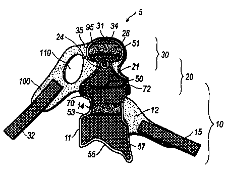
Figures 1-8 illustrate an orthotic protective device 5, namely a brace to
protect
and prevent hyperextension and hyperfexion movements of the metacarpal,
carpal,
radius and ulna regions and provide normal pitch and yaw movements of a user.
7

CA 02532210 2006-01-11
WO 2005/007022 PCT/US2004/021728
The orthotic protective device 5 collectively includes a hinge system 20
positioned
between a base unit 10 and a metacarpal unit (also known as the hand unit) 30.
Figures 1 and 2 show the base unit 10 incorporates a substantially rigid,
elongated support member 11 including an interior surface 59 and an exterior
surface 57 having a distal end 50, a middle region 53 and a proximate end 55.
The
elongated support member 11 is preferably shaped as an inverted "U" capable of
being positioned on a dorsal side of the radius-ulna region of the user and
substantially surrounds and conforms to the user's forearm to ensure a secure
fit as
seen in Figures 3 and 4. Here, the support member 11 may either be formed as a
one-piece unit; or alternatively, as a segmented body where each segment is
joined
to one another to adapt to the user's specific body specifications. The
support
member 11 may be made of, but not limited to, such materials as moldable
carbon
fiber, epoxy matrix carbon fiber, Kevlar composite material, hard plastic or
thermoplastic material which may be mass produced as an off-the-shelf item or
customized to fit a particular individual.
Figure 2 shows the interior surface 59 of the elongated support member 11 is
lir ed with at least one support-pad f2ettached therein. The support pad(s)"
12 may
be fastened to the interior surface 59 by, but not limited to, hook and loop
material
such as VelcroTM, adhesive, pins, screws, buttons and the like. The support
pad(s)
12 may contour a substantial portion or entire surface area of the interior
surface
59. In the most preferred embodiment, at least one of the support pads 12 has
a
tongue which projects beyond the surface area of the interior surface 59 and
is
designed to extend around the volar surface of the radius-ulna region.
8

CA 02532210 2006-01-11
WO 2005/007022 PCT/US2004/021728
At least one releasable fastener 15 is coupled to the exterior surface 57 of
the
elongated support member 11, preferably on the middle region 53 as depicted in
Figures 3, 5 and 6. The releasable fastener 15, preferably a strap, may be
fastened
to the exterior surface 57 by, but not limited to, VelcroTM, adhesive, pins,
screws,
buttons, nuts, bolts and the like. Specifically, a first end of the releasable
fastener
is mounted, preferably to a hook and loop patch adhered onto the exterior
surface 57 of the support member 11. A second end of the releasable fastener
15
orthogonally extends from the exterior surface 57 and is attached to the
tongue of
the support pad 12.
10 The middle region 53 of the exterior surface 57 is adjacently positioned to
the
proximate end 55 and is positioned across the radius-ulna region. Desirably,
the
proximate end 55 may be asymmetrically configured to impart comfort and
prevent
a feeling of confinement to the user. The distal end 50 is also located
adjacent to
the middle region 53 and is near and extends across the carpal region.
15 The distal end 50 has opposing sides 70, 72, where each side includes an
aperture 16 bored through the support member 11 and capable of receiving
connectors 30 therein. Each aperture 16 - has a reinforcement perpendicularly
extending therefrom designed to surround and support the connectors 90
inserted
through the apertures 16.
The hinge system 20 comprises a shell 21 having polar extended sides 22, 23
and a lip 24. An interior pad 26 is removably attached underneath the polar
extended sides 22, 23 thereby providing comfort to the carpal region of the
user.
Each polar extended side 22, 23 has an aperture 28 capable of accepting
fasteners
therein. These apertures 28 directly correspond to and are positioned
underneath
9

CA 02532210 2010-11-17
WO 2005/007022 PCT/US2004/021728
the apertures 16 of the support member 11 In order to accept the inserted
connectors 90.
The connected apertures 16, 28 form an articulated joint allowing the hinge
system 20 to move at about a 45 angle in an upward vertical manner or until
the
hinge system 20 abuts the base unit 10, thereby limiting the extertsion of the
carpal
area specific to the user's maximum range of motion as seen in Figure 7.
Figure 8
depicts the articulated joint having no flexion resistance.
Operatively speaking, the joint may be flexed at about a 150 angle in a
downward manner only limited by the user's natural range of motion. In an
alternative embodiment, the angle of the articulated joint may be severely
limited
by incorporating stops 120 on both the shell 21 and the support member 11 to
limit
extension, flexion and ulnar-radial deviation. As each stop abuts one another,
the
range of motion is inhibited.
The orthotic protective device 5 undergoes a scanning and molding process,
namely by first scanning and measuring a user's physiological specifications;
and
then translating the measurements into a mold, The mold is then fabricated by
utilizing a wet lay up-process using a combination of epoxy resin, carbon
fiber and
KEVLAR' (aramid fiber) composite materials. This process allows for normal
movement of the carpal region. The resulting protective device 5 is designed
to limit
both extension and flexion of the carpal region specific to the patient's
maximum range
of motion. Further, during the scanning, molding and fabrication process, the
stops
120 are formed onto the shell 21 and the support member 11 thereby limiting
the
user's movement, both natural and hyperextended/hyperflexed movements, as
shown
in Figure 8.
to

CA 02532210 2006-01-11
WO 2005/007022 PCT/US2004/021728
The lip 24 has an aperture 28 designed to receive a swivel joint 95 or other
connector. The aperture 28 preferably has a reinforcement orthogonally
projecting
therefrom and surrounding the swivel joint 95 or alternate connector.
The metacarpal unit 30 incorporates a casing 31 including an internal surface
50,
and an external surface 51 having an anterior end 52 and a posterior end 54.
An
internal pad 35 has a tongue 100 and is removably connected to the internal
surface
50 of the casing 31, preferably by a hook and loop means. Here, either a hook
or
loop patch is fastened to the internal surface 50 and is adapted to accept the
internal pad 35 as the loop or hook, respectively, are mated. The internal pad
35
substantially conforms to the surface area of the internal surface 50 and the
tongue
100 projects outwardly and is designed to extend around the volar surface of
the
user's palm. The tongue 100 has a digit, namely a thumb, orifice 110 allowing
the
digit to be inserted therethrough.
A first end of an attachment means 32, namely a strap, is fastened to the
casing
31, preferably by a hook and loop connector being adhered to the external
surface
51 of the casing 31. The attachment means 32 has the corresponding loop or
hook
patch; respectively; us tt tO _7am to the former patch. A second- end extends
transversely across the external surface and orthogonally extends from the
external
surface 51 of the casing 31 and is attached to the tongue 100 of the internal
pad 35.
Each pad, namely the support pad(s) 12, interior pad 26 and internal pad 35
are
resistently compressible, high surface-friction pads designed to secure the
orthotic
protective device 5 to the user. The pads 12, 26 and 35 may be made from such
materials as, but not limited to, open cell foam, closed cell foam,
viscoelastic
polymer-gel, cotton, liquid material, granular material or air material. In
the most
11

CA 02532210 2006-01-11
WO 2005/007022 PCT/US2004/021728
preferred embodiment, each pad 12, 26, 35 may include cooling and/or heating
coils
42 embedded within each pad 12, 26, 35 to either provide the user a cooling or
heated effect to reduce swelling and provide relief. These coils 42 are
electrically
connected to a temperature control means 40 which may be manipulated by the
user to produce a desired effect.
The posterior end 54 of the casing 31 has an aperture 58 which corresponds to
the aperture 28 located on the lip 24 of the shell 21. The swivel joint 95 or
other
connector is accepted by both apertures 28, 58 alike and provides for the
metacarpal
unit 30 to move in a lateral fashion with respect to the hinge system 20.
Specifically, the swivel joint 95 allows up to a 60 turn on each side of its
horizontal
axis providing for normal movement of the carpal region. In a preferred
embodiment, the swivel joint 95, as well as the connectors 90 may comprise of
quick
release pins allowing for each addition or subtraction of either the base unit
10,
metacarpal unit 30 or other accessory or accessories adapted to fit thereto.
Further,
in a preferred embodiment, the casing 31 and the shell 21 may be made of such
materials as, but not limited to, moldable carbon fiber, epoxy matrix carbon
fiber,
Kevlar=-composite material, hard--plastic or thermoplastic material- which
either being
mass produced or having a more customized fit for an individual.
While the foregoing description is exemplary of the preferred embodiment of
the
present invention, those of ordinary skill in the relevant arts will recognize
the many
variations, alterations, modifications, substitutions and the like as are
readily
possible, especially in light of this description, the accompanying drawings
and
claims drawn thereto. Therefore, the foregoing detailed description should not
be
construed as a limitation of the scope of the present invention, which is
limited only
12

CA 02532210 2006-01-11
WO 2005/007022 PCT/US2004/021728
by the claims appended hereto. The invention is, therefore, claimed in any of
its
forms or modifications within the proper scope of the appended claims
appropriately
interpreted in accordance with the doctrine of equivalents.
INDUSTRIAL APPLICABILITY:
The present invention finds specific industrial applicability in the medical
and
athletic industries.
13

Representative Drawing
A single figure which represents the drawing illustrating the invention.
Administrative Status

2024-08-01:As part of the Next Generation Patents (NGP) transition, the Canadian Patents Database (CPD) now contains a more detailed Event History, which replicates the Event Log of our new back-office solution.

Please note that "Inactive:" events refers to events no longer in use in our new back-office solution.

For a clearer understanding of the status of the application/patent presented on this page, the site Disclaimer , as well as the definitions for Patent , Event History , Maintenance Fee  and Payment History  should be consulted.

Event History

Description Date
Time Limit for Reversal Expired 2018-07-09
Letter Sent 2017-07-10
Maintenance Request Received 2016-07-06
Inactive: Payment - Insufficient fee 2015-09-16
Inactive: Reversal of deemed expired status 2015-09-16
Time Limit for Reversal Expired 2015-07-08
Inactive: Late MF processed 2015-06-19
Letter Sent 2014-07-08
Inactive: Office letter 2013-07-16
Revocation of Agent Requirements Determined Compliant 2013-07-16
Revocation of Agent Request 2013-07-02
Maintenance Request Received 2013-07-02
Inactive: Correspondence - PCT 2013-05-15
Grant by Issuance 2012-11-13
Inactive: Cover page published 2012-11-12
Inactive: Final fee received 2012-08-30
Pre-grant 2012-08-30
Letter Sent 2012-07-23
Inactive: Single transfer 2012-06-28
Letter Sent 2012-06-14
Notice of Allowance is Issued 2012-06-14
Inactive: Approved for allowance (AFA) 2012-06-12
Amendment Received - Voluntary Amendment 2012-03-06
Inactive: S.30(2) Rules - Examiner requisition 2011-09-12
Amendment Received - Voluntary Amendment 2011-05-17
Inactive: S.30(2) Rules - Examiner requisition 2011-04-11
Amendment Received - Voluntary Amendment 2010-11-17
Inactive: S.30(2) Rules - Examiner requisition 2010-10-14
Letter Sent 2009-04-23
Amendment Received - Voluntary Amendment 2009-03-30
Request for Examination Received 2009-03-25
Request for Examination Requirements Determined Compliant 2009-03-25
All Requirements for Examination Determined Compliant 2009-03-25
Inactive: Cover page published 2006-03-15
Inactive: Inventor deleted 2006-03-13
Inactive: Notice - National entry - No RFE 2006-03-13
Application Received - PCT 2006-02-09
National Entry Requirements Determined Compliant 2006-01-11
Small Entity Declaration Determined Compliant 2006-01-11
Application Published (Open to Public Inspection) 2005-01-27

Abandonment History

There is no abandonment history.

Maintenance Fee

The last payment was received on 2012-06-20

Note : If the full payment has not been received on or before the date indicated, a further fee may be required which may be one of the following

  • the reinstatement fee;
  • the late payment fee; or
  • additional fee to reverse deemed expiry.

Patent fees are adjusted on the 1st of January every year. The amounts above are the current amounts if received by December 31 of the current year.
Please refer to the CIPO Patent Fees web page to see all current fee amounts.

Fee History

Fee Type Anniversary Year Due Date Paid Date
Basic national fee - small 2006-01-11
MF (application, 2nd anniv.) - small 02 2006-07-10 2006-06-20
MF (application, 3rd anniv.) - small 03 2007-07-09 2007-06-19
MF (application, 4th anniv.) - small 04 2008-07-08 2008-07-07
Request for examination - small 2009-03-25
MF (application, 5th anniv.) - small 05 2009-07-08 2009-07-08
MF (application, 6th anniv.) - small 06 2010-07-08 2010-06-18
MF (application, 7th anniv.) - small 07 2011-07-08 2011-07-05
MF (application, 8th anniv.) - small 08 2012-07-09 2012-06-20
Registration of a document 2012-06-28
Final fee - small 2012-08-30
MF (patent, 9th anniv.) - small 2013-07-08 2013-07-02
MF (patent, 10th anniv.) - small 2014-07-08 2015-06-19
Reversal of deemed expiry 2015-07-08 2015-06-19
Reversal of deemed expiry 2015-07-08 2016-07-06
MF (patent, 11th anniv.) - small 2015-07-08 2016-07-06
MF (patent, 12th anniv.) - small 2016-07-08 2016-07-06
Owners on Record

Note: Records showing the ownership history in alphabetical order.

Current Owners on Record
ALLSPORT DYNAMICS, INC.
Past Owners on Record
JEFFREY L. BREWER
Past Owners that do not appear in the "Owners on Record" listing will appear in other documentation within the application.
Documents

To view selected files, please enter reCAPTCHA code :


To view images, click a link in the Document Description column. To download the documents, select one or more checkboxes in the first column and then click the "Download Selected in PDF format (Zip Archive)" or the "Download Selected as Single PDF" button.

List of published and non-published patent-specific documents on the CPD .

If you have any difficulty accessing content, you can call the Client Service Centre at 1-866-997-1936 or send them an e-mail at CIPO Client Service Centre.


Document
Description 
Date
(yyyy-mm-dd) 
Number of pages   Size of Image (KB) 
Claims 2006-01-10 4 108
Abstract 2006-01-10 2 79
Description 2006-01-10 13 533
Drawings 2006-01-10 3 166
Representative drawing 2006-03-13 1 26
Claims 2009-03-29 15 476
Description 2009-03-29 13 539
Description 2010-11-16 11 481
Drawings 2010-11-16 3 110
Description 2010-11-16 14 578
Claims 2011-05-16 11 481
Description 2012-03-05 14 581
Claims 2012-03-05 11 452
Representative drawing 2012-10-15 1 21
Reminder of maintenance fee due 2006-03-12 1 111
Notice of National Entry 2006-03-12 1 193
Reminder - Request for Examination 2009-03-09 1 117
Acknowledgement of Request for Examination 2009-04-22 1 175
Commissioner's Notice - Application Found Allowable 2012-06-13 1 161
Courtesy - Certificate of registration (related document(s)) 2012-07-22 1 125
Notice: Maintenance Fee Reminder 2014-04-08 1 119
Maintenance Fee Notice 2014-08-18 1 170
Second Notice: Maintenance Fee Reminder 2015-01-11 1 119
Notice: Maintenance Fee Reminder 2015-04-08 1 118
Notice of Insufficient fee payment (English) 2015-09-15 1 91
Maintenance Fee Notice 2015-11-25 1 170
Late Payment Acknowledgement 2015-11-25 1 163
Notice: Maintenance Fee Reminder 2016-04-10 1 120
Notice: Maintenance Fee Reminder 2017-04-10 1 120
Maintenance Fee Notice 2017-08-20 1 181
Second Notice: Maintenance Fee Reminder 2018-01-08 1 130
Notice: Maintenance Fee Reminder 2018-04-09 1 121
PCT 2006-01-10 2 90
Correspondence 2007-08-28 2 47
Correspondence 2012-08-29 1 38
Correspondence 2013-05-14 1 24
Correspondence 2013-07-01 1 22
Fees 2013-07-01 2 41
Correspondence 2013-07-15 1 13
Correspondence 2013-07-15 1 20
Fees 2015-08-17 3 204
Fees 2015-06-18 4 191
Fees 2015-09-24 5 234
Fees 2016-07-05 1 24