Note: Descriptions are shown in the official language in which they were submitted.
CA 02533511 2011-03-11
COMPUTER PHYSICAL SECURITY DEVICE WITH RETRACTABLE
CABLE
BACKGROUND OF THE INVENTION
[0002] The present invention generally relates to locking devices, and more
specifically,
to a locking device that includes a retractable cable.
[0003] A user may have many different portable electronic devices. For
example, portable
electronic devices may be laptop computers, portable digital assistants
(PDAs), desktop
computers, flat screen TVs, Blackberry devices, Goodlink devices, digital
cameras, portable
music players (e. g., IPODs), etc. These devices are typically small but very
expensive.
When left unattended, electronic devices are easily stolen, and because of
their expensive
nature, there may be a higher likelihood that they are stolen. Accordingly,
security devices
have been developed in order to prevent theft of these devices.
[0004] The security devices often include a cable or tether. The cable or
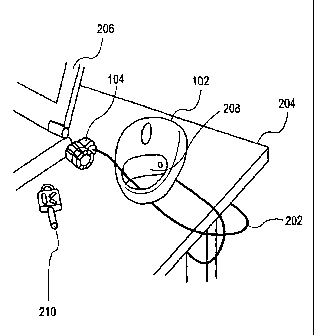
tether is typically
looped around a stationary object in order to secure the security device to
the stationary
object. When the cable is not in use, the cable is coiled for easier storage.
Generally, a user
coils the cable, and often, the coiled cable is not compact and becomes
uncoiled or tangled
with other devices. Also, the coiled cable may be bulky and hard to carry.
[0005] Accordingly, an improved security device is desired.
BRIEF SUMMARY OF THE INVENTION
[0006] The present invention generally relates to a security device that
includes a
retractable cable. In one embodiment, the security device is for locking a
portable electronic
device. The security device comprises a locking device, a cable coupled to the
locking
device, and a housing including a retracting mechanism. The retracting
mechanism is
configured to enable the cable to be extended such that the locking device is
extended from
the housing. The cable is looped around a stationary object and the locking
device can then
be attached to the portable electronic device. The portable electronic device
is then secured.
The locking device may be unlocked and unattached from the portable electronic
device.
I
CA 02533511 2011-03-11
The retracting mechanism is then configured to retract the cable into the
housing. Thus, the
locking device is also retracted. In one embodiment, the locking may be
retracted such that
it is flush with or within an outer surface of the housing.
[0007] In one embodiment, there is provided a security device for a portable
electronic
device, the security device comprising: a locking device; a cable coupled to
the locking
device; a housing including a retracting mechanism, wherein the retracting
mechanism is
configured to enable the cable to be extended such that the locking device is
extended from
the housing and can be attached to the portable electronic device in such a
way to inhibit
theft of the portable electronic device, wherein the retracting mechanism is
further
configured to retract the cable into the housing, and wherein the housing
comprises a
compartment, wherein the locking device and cable can be looped through the
compartment
when locking the locking device to the portable electronic device.
[0008] In another embodiment, there is provided a system for securing a
portable
electronic device, the system comprising: a portable electronic device, the
portable
electronic device including a slot; a security device, the security device
comprising: a
locking device; a cable coupled to the locking device; and a housing including
a retracting
mechanism, wherein the retracting mechanism is configured to enable the cable
to be
extended such that the locking device is extended from the housing and can be
attached to
the slot of the portable electronic device in such a way to inhibit theft of
the portable
electronic device, wherein the retracting mechanism is further configured to
retract the cable
into the housing, wherein the housing comprises a compartment, wherein the
locking device
and cable can be looped through the compartment when locking the locking
device to the
portable electronic device.
[0009] In yet another embodiment, there is provided a method for securing a
portable
electronic device, the method comprising: providing a security device
comprising a housing
that includes a cable and a locking device that are retractable from an
extended position
towards the housing; extending the locking device and the cable from the
housing of the
security device to the extended position; attaching the locking device to the
portable
electronic device; locking the locking device, wherein theft of the portable
electronic device
is inhibited; unlocking the locking device; and retracting the locking device
and the cable
from the extended position to the housing, and wherein the method further
comprises
looping the locking device and cable around a stationary object; and passing
the locking
2
CA 02533511 2011-03-11
device and cable through a compartment in the housing before attaching the
locking device
to the portable electronic device.
[0009a] In another embodiment, there is provided a method for securing a
portable
electronic device, the method comprising: providing a security device
comprising a housing
that includes a cable and a locking device that are retractable from an
extended position;
extending the locking device and the cable from the housing of the security
device to the
extended position; attaching the locking device to the portable electronic
device; locking the
locking device, wherein theft of the portable electronic device is inhibited;
unlocking the
locking device; and retracting the locking device and the cable from the
extended position
into the housing, and wherein the method further comprises passing the locking
device and
cable through a compartment in the housing before attaching the locking device
to the
portable electronic device.
[0010] A further understanding of the nature and the advantages of the
inventions
disclosed herein may be realized by reference of the remaining portions of the
specification
and the attached drawings.
2a
CA 02533511 2006-01-20
WO 2005/010303 PCT/US2004/023593
BRIEF DESCRIPTION OF THE DRAWINGS
[0011] Figs. IA and 1B depict various views of a security device according to
one
embodiment of the present invention.
[0012] Fig. 2 depicts an additional view of an embodiment of the security
device.
[0013] Figs. 3A, 3B, and 3C depict various views of the security device
according to one
embodiment of the present invention.
[0014] Fig. 4 shows an exploded view of the security device according to one
embodiment
of the present invention.
[0015] Figs. 5A-5E depict a method of securing a portable device using the
security device
according to one embodiment of the present invention.
[0016] Figs. 6-8 depict various views of a locking device according to one
embodiment of
the present invention.
DETAILED DESCRIPTION OF THE INVENTION
[0017] Figs. 1A and 113 depict various views of a security device 100
according to one
embodiment of the present invention. As shown, security device 100 includes a
housing 102
and a locking device 104. In one embodiment, housing 102 is made from a sturdy
material
such a plastic or a metal. A person skilled in the art will understand that
other materials may
be used. In one embodiment, housing 102 is made from a material such that it
may be hard to
break the material. The material should be hard to break because, as will be
described below,
housing 102 may be used in securing a portable electronic device.
[0018] In one embodiment, housing 102 provides a very thin design. For
example, a length
L may be up to 13 centimeters, a width W may be up to 10 centimeters, and a
thickness T up
to 7.25 centimeters. Also, security device 100 may weigh approximately 3.75
lbs. Although
these dimensions are described, it will be understood that a person skilled in
the art will also
appreciate other dimensions for housing 102.
[0019] In one embodiment, locking device 104 is configured to be attached to a
portable
electronic device. A portable electronic device includes a laptop computer,
desktop
computer, PDA, Blackberry device, cellular phone, digital camera, flat screen
monitor,
television, portable music player etc. It will be understood that the person
skilled in the art
will appreciate other portable electronic devices that may be used. The
portable electronic
3
CA 02533511 2006-01-20
WO 2005/010303 PCT/US2004/023593
devices may be primarily mobile or stationary. For example, a cellular phone
is primarily
mobile in that it is moved around. A flat screen television may be primarily
stationary
because it is not moved often. The television, however, may be moved and thus
may need to
be secured from theft using a security device 100.
[0020] In one embodiment, locking device 104 is configured to be attached to a
portable
electronic device using a security slot (which preferably has dimensions of
about 3 mm by
about 7 mm and is generally rectangular in shape). The portable electronic
device includes a
security slot in which locking device 104 is inserted. Locking device 104 is
then locked to
the security slot. The process of locking device 104 to a portable electronic
device will be
described in more detail below.
[0021] As shown in Figs. IA and 1B, locking device 104 is enclosed in housing
102.
Accordingly, security device 100 provides a compact structure when locking
device 104 is
not in use. In one embodiment, locking device 104 may be flush with an outer
surface of
housing 102. Thus, locking device 104 is found within housing 102.
[0022] Fig. 2 depicts an additional view of an embodiment of security device
100. Security
device 100 is shown with locking device 104 extended from housing 102. Locking
device
104 is coupled to a cable 202, which is coupled to housing 102. A retracting
mechanism (not
shown) is included in housing 102 and is coupled to cable 202.
[0023] In one embodiment, cable 202 may be made from a strong material. For
example,
cable 202 may be formed from steel, any other metal, or any other material
(e.g., a cable
made from KevlarTM fibers or poly p-phenyleneterephthamide fibers). In
addition, cable 202
may include a cable coating such as a PVC cable coating. The diameter of cable
202 may be
1.5mm without the PVC coating and 2.5mm with the PVC coating. Cable 202, in
one
embodiment, may withstand at least 200 lbs. of pull force. Cable 202 may be of
a variable
length but may be four feet in length in one embodiment. Although these
characteristics are
mentioned, it will be understood that cable 202 may have other
characteristics, such as cable
202 may have a different thickness.
[0024] As shown, locking device 104 and cable 202 have been extended from
housing 102.
In one embodiment, a button may be provided such that, when pushed, it allows
cable 202
and locking device 104 to be extended. When the button is released, the cable
is locked in
that it cannot be extended anymore. When the button is pushed again, cable 202
and locking
device 104 may be retracted into housing 102. A person skilled in the art will
appreciate
4
CA 02533511 2006-01-20
WO 2005/010303 PCT/US2004/023593
other methods of using devices to extend and retract cable 202. For example,
the button may
be any release mechanism that allows extension of cable 202 and causes
retraction of cable
202. In one embodiment, a slidable button may be provided that slides to a
position that
allows extension of cable 202 and slides to a position that causes retraction
of cable 202.
[00251 As cable 202 and locking device 104 are extended from housing 102, they
may be
looped around an object 204. In one embodiment, object 204 may be a stationary
object.
Locking device 104 and cable 202 may then be passed through a compartment 208
in housing
102. Locking device 104 is attached to a portable electronic device 206 and
locked to
portable electronic device 206. In one embodiment, locking device 104 may be
locked (or
unlocked) using key 210, a combination, or any other locking mechanism.
[00261 By looping locking device 104 and cable 202 around a fairly stationary
object 204
and through compartment 208, locking device 104 may be attached to portable
device 206 in
a secure manner. If a user attempts to move portable device 206, security
device 100 restricts
the movement of portable device 206. Accordingly, a user may not be able to
remove
portable device 206 from the area in which it has been locked. Although
passing locking
device 104 though compartment 208 is described, it will be recognized that
other methods of
securing portable electronic device 206 may be used. For example, a second
loop on housing
102 may be provided such that locking device 104 is passed through the second
loop. Also, a
loop on cable 202 may be provided such that locking device 104 is passed
through the loop.
[00271 Figs. 3A, 3B, and 3C depict various views of security device 100
according to one
embodiment of the present invention. As shown, locking device 104 and cable
202 are in a
retracted position.
[00281 Locking device 104 and cable 202 maybe retracted into housing 102 by
various
methods. For example, a button may be provided that, when pushed or unpushed,
may cause
a retracting mechanism to retract locking device 104 and cable 202 into
housing 102.
Additionally, retracting mechanism may be activated to retract cable 202 and
locking device
104 into housing 102 by pulling slightly on cable 202 when cable 202 is in a
stationary
position.
[00291 As shown, locking device 102 and cable 202 are enclosed within housing
102. In
one embodiment, cable 202 is wound around a retracting mechanism in housing
102. Cable
202 is thus compactly stored in housing 102.
5
CA 02533511 2006-01-20
WO 2005/010303 PCT/US2004/023593
[0030] Locking device 104 is additionally found within housing 102. In one
embodiment,
locking device 104 is substantially flush with an outer surface of housing
102. Also, covers
302 may be included in the security device 100. Covers 302 may open and close.
[0031] When closed, covers 302 enclose housing 102 such that locking device
104 is
completely enclosed within housing 102. Fig. 3C depicts embodiment of security
device 100
with covers 302 closed. As shown, security device 100 is in a very compact
form.
[0032] Although covers 302 are shown as being included with security device
100, it will
be understood that covers 302 may not be included in security device 100.
Rather, locking
device 104 and cable 202 may be located within housing 102 without covers. For
example,
Fig. 2 depicts a security device 100 without covers 302.
[0033] Fig. 4 shows an exploded view of security device 100 according to one
embodiment
of the present invention. Housing 102 may be formed from a clamshell design
and include
the first outer cover 406 and a second outer cover 414. Additionally, a cover
302 and logo
area 402 may be attached to outer housing 406 or 414. Outer housing 406 and/or
414 may be
made from a sturdy material, such as a plastic or metal.
[0034] A retracting device 407 includes a rotor 408, a coiling device 410, and
a base 412.
Although these parts are shown in the retracting mechanism 407, it will be
understood that
retracting mechanism 407 may include other parts or may be in a different
form. Retracting
mechanism 407 is configured to retract cable 202 and locking device 104 into
housing 102.
Additionally, retracting mechanism 407 allows the extension of.cable 202 and
locking device
104 from housing 102.
[0035] In operation, cable 202 is wound around base 412. A spring may be
included such
that rotor 408 and coiling device 410 are turned thereby retracting cable 202
around base 412.
[0036] The assembly of security device 100 may include coupling cable 202 to
retracting
mechanism 407. In one embodiment, a first end 418 of cable 202 may be attached
to base
412. A second end 420 may then be coupled to locking device 104. Any kind of
adhesive
may be used to attach first end 418 to base 412 and second end 420 to locking
device 104.
[0037] Rotor 408, coiling device 410, and base 412 are then coupled together
to form
retracting mechanism 407. Second outer housing 414 may include a peg 422 that
is
configured to couple to retracting mechanism 407. Peg 422 is configured to be
passed
through an aperture that is formed in rotor 408, coiling device 410, and base
412. Peg 422
6
CA 02533511 2006-01-20
WO 2005/010303 PCT/US2004/023593
allows retracting mechanism 407 to spin around peg 422. It will be understood
that peg 422
may be in other forms, such as any kind of device that may hold retracting
mechanism 407 in
housing 102.
[0038] First outer housing 406 and second outer housing 414 are then coupled
together. In
one embodiment, a clip 416 is used to secure first outer housing 406 and
second outer
housing 414 together. Outer cover 302 and logo area 402 may then be coupled to
first outer
housing 406. In one embodiment, screws may be used to attach cover 302 and
logo area 402
to first outer housing 406. Also, any adhesive may be used, such as glue.
Additionally, a
storage area in housing 102 may be provided such that keys or other items may
be stored in
housing 102.
[0039] A spring and retracting mechanism 407 is strong enough to fully retract
locking
device 104 and cable 202 into housing 102. In addition, locking device 104 and
cable 202
may withstand at least 200 lbs. of pull force without pulling out of the
housing 102.
[0040] Retracting mechanism 407 may be configured to withstand at least 1,000
cycles. A
cycle may be extending the cable to full length, opening covers 302, looping
the cable
through the device, unlooping the cable 202, and retracting cable 202.
Although a 1,000
cycles are mentioned, it will be understood that the retracting mechanism 407
may withstand
any number of cycles.
[0041] Figs. 5A-5E depict a method of securing a portable device 206 using
security device
100 according to one embodiment of the present invention. As depicted in Fig.
5A, cable 202
is extended from housing 102. Locking device 104 and cable 202 is then looped
around
object 204. In this case, object 204 is a table and more specifically, a leg
of a table.
However, locking device 104 and cable 202 may be looped around other devices,
such as
looped under a table and through a hole in the table, a chair, or any other
fairly immovable
object.
[0042] Locking device 104 and cable 202 are then looped through compartment
208. In
one embodiment, compartment 208 is a compartment that stored locking device
104 when it
was not in use. In one embodiment, covers 302, are opened to allow locking
device 104 and
cable 202 to be inserted through compartment 208. In other embodiments,
security device
100 does not include covers.
7
CA 02533511 2006-01-20
WO 2005/010303 PCT/US2004/023593
[00431 In Fig. 5B, locking device 104 is inserted into a slot 15 in portable
device 206.
Locking device 104 includes a spindle 504 that is configured to be inserted
into slot 15. The
locking of locking device 104 in slot 15 will be described in more detail
below. As shown, a
key 210 has been inserted into locking device 104. This position is an
unlocked position for
locking device 104.
[0044] Fig. 5C depicts locking device 104 as it is locked to portable device
106. In one
embodiment, locking device 104 is inserted into slot 15. Key 210 is then
turned. When key
210 is turned a certain amount, cross-member 504 such as a T-shaped cross
member is
misaligned with slot 15. Misaligning cross-member 504 with an inner surface of
portable
device 106 thereby inhibits removal of locking device 104 from portable
electronic device
206. Cross-member 504 is turned such that it cannot be removed from slot 15
without being
returned to its original position. Accordingly, removing locking device 104
from slot 15 is
restricted. Other types of locking devices that are suitable for use in
embodiments of the
invention are described below.
[0045] In Fig. 5D, key 210 is removed from locking device 104. Locking device
104
cannot be removed from portable device 206 without using key 210.
[0046] Fig. 5E depicts locking device 104 being attached to portable device
206. As
shown, cable 202 has been looped around object 204, through compartment 208
and attached
to portable device 206. If a user tries to move portable device 206, the
movement is
restricted by cable 202. Accordingly, theft of portable device 206 may be
restricted using
security device 100.
[0047] Accordingly, security device 100 provides a retractable, portable
security lock. The
cable is easy to retract and enables portability and mobility while providing
security. The
housing may form part of the locking mechanism and thus performs a dual
function. The
small compact lock design is designed for portable devices and may not block
other ports.
The locking device also provides superior locking strength when attached to a
slot 502 in a
portable electronic device 206.
[0048] Different embodiments of locking devices 104 will now be described.
Locking
device 104 may be provided in many forms. A suitable locking device 28 is
shown in FIG. 7
and the exploded view of FIG. 6. Locking device 28 includes a hollow shell 90
and a nose-
piece 92 which, in combination, form a housing. Shell 90 has a hollow
cylindrical interior
cavity 94, and an integral apertured plate 96 at one end. A pin 98 is inserted
through an
8
CA 02533511 2006-01-20
WO 2005/010303 PCT/US2004/023593
aperture (not shown) in nose-piece 92 to engage a slot 102 in shell 90. Pin 98
is designed to
shear when torque is applied to nose-piece 92 so that an unauthorized attempt
to remove the
attachment mechanism will simply shear the pin and allow the nose-piece to
freely rotate
without degrading the attachment of the locking device to the component to be
protected.
Slot 102 is axially elongate so that limited axial movement is allowed between
shell 90 and
nose-piece 92. The forward end of nose-piece 92 has a plate 93 having a
central aperture 95.
[0049] A cylindrical collar 106 circumscribes the outer portion of shell 90
and occupies the
slot laterally defined by plate 96 and the aft surface 108 of nose-piece 92.
Collar 106 has an
integral tab 110 with an aperture 112 adapted to receive one end of cable 32.
Cable 32 is
dead-ended into tab 110 and attached so that it cannot be removed.
[0050] A spindle 114 has a cylindrical portion 116 adapted to be received
within a
cylindrical lock 118 in shell 90. Cylindrical lock 118 includes a front
cylinder 119, and a
back cylinder 120. A blunt pin or set screw 121 is inserted through an
aperture 125 in shell
90, and through a corresponding aperture 123 in back cylinder 120, to lock the
front cylinder
rotationally with respect to shell 90. Correspondingly, pin or set screw 127
engages a
relatively smaller aperture 129 in front cylinder 119, and a widening 131 in
slot 133 in the
cylindrical portion 116 of spindle 114. Front cylinder 119 is thus fixed
rotationally With
respect to spindle 114.
[0051] As with conventional cylindrical locks, a plurality of pins normally
span the
interface between front cylinder 119 and back cylinder 120 so that the
cylinders are
rotationally locked together, thus preventing relative rotation between
locking shell 90 and
spindle 114. However, a key 210 is insertable through the apertured plate 96
of shell 90 to
engage front cylinder 119. The correct key 210 will have bosses located to
depress the pins
passing between cylinders 119 and 120 so that such pins do not span the
interface between
the cylinders, allowing the cylinders to rotate with respect to one another.
In this fashion,
spindle 114 can be rotated with respect to shell 90 only upon insertion and
rotation of the
appropriate key 210.
[0052] Spindle 114 also includes a shaft 122, and a crossmember 124 at the
free end of the
shaft. An abutment mechanism 126 has an abutment plate 128 adapted to fit
within nose-
piece 92, and a pair of pins 130 adapted to extend outwardly through aperture
95. A spring
132 is located between abutment plate 128 and nose-piece 92 to bias the
cylindrical portion
116 of spindle 114 and the abutment plate rearwardly. Abutment plate 126 has
an elongate
9
CA 02533511 2006-01-20
WO 2005/010303 PCT/US2004/023593
aperture 134 which allows crossmember 124 to extend through the aperture
plate. A plastic
bushing 136 is fixed to the surface of plate 93 so that the mechanism does not
scar the
equipment to which it is attached.
[00531 The insertion of locking device 28 into the exterior wall 137 of a
piece of equipment
is illustrated by way of reference to FIGS. 8A and 8B. Wall 136 has a slot
138. The
peripheral dimensions of crossmember 124, and also those of pins 130 and shaft
122 in
combination, is that the crossmember is generally rectangular, having straight
sides and semi-
circular ends. In the preferred embodiment, the long dimension of the
crossmember 124 is
6.75 millimeters, while the short dimension is 2.75 millimeters, each being
slightly less than
the corresponding dimension of slot 138. The peripheral dimensions of the pins
130 and
shaft 122 also closely conform to the interior dimensions of slot 138. As with
crossmember
124, pins 130 in shaft 122 have a long dimension of 6.75 millimeters, and a
short dimension
of 2.75 millimeters. Simply put, locking device 28 is designed to fit into the
same slot as
locking device 12.
[00541 As illustrated in FIG. 8A, crossmember 124 is aligned with pins 30 so
that the
crossmember can be inserted into slot 138. When fully inserted, the space in
the slot is
essentially occupied by pins 130 and shaft 122. If necessary, plate 96 can be
depressed to
push the cylindrical portion of spindle 114 against spring 132. Once
crossmember 124 has
been fully inserted through slot 138, a key 140 engaging lock mechanism I1B
(see FIG. 7) is
used to rotate the spindle 90 degrees and misalign crossmember 124 and slot
138.
[00551 In operation, both locking device 12 and locking device 28 are attached
to an item
of computer or other equipment which has a specially designed slot 72, 138.
First, the
crossmember 54, 124 is aligned with the pins 60, 130, for insertion to the
crossmember
through the slot. The spindle 46, 114 is then rotated relative to the housing
to misalign the
crossmember 54, 124 relative to the slot. The spindle is locked in this
configuration by
passing the cable through the mating slot 16, 48 in the first embodiment, or
using the key 140
in the second embodiment. Either way, the locking device is extremely
difficult to disengage
by anyone not having the appropriate key 24, 140. Any unauthorized attempt to
remove the
locking device from the computer component will most likely result in
significant damage to
the computer housing, making the computer difficult to resell and greatly
reducing its theft
potential.
CA 02533511 2011-03-11
[0056] Other embodiments of locking device 104 are further described in U. S.
Patent No.
6,006,557 and U. S. Patent No. 5,202,989. Also, in another example, in U. S.
Patent No.
6,321, 579, a locking device 104 may include tabs and a hook arm. The tabs and
hook arm
are configured to be inserted into a slot. Once inserted into the slot, the
hook arm may be
pivoted such that it latches onto an inside surface of the slot. Accordingly,
the locking
device is secured within the slot and cannot be removed. Another locking
device is
described in U. S. Patent No. 6,591,642. This locking device includes an L-
shaped hook that
is inserted into a security slot in a portable electronic device. A user then
pushes a button or
cylinder at the end of the device to push out a bolt to fill the security slot
and thereby secure
the locking device to the portable electronic device.
[0057] In order to unlock the locking device, the hook arm is pivoted in an
opposite
direction such that the hook arm is unlatched from the inside surface of the
slot. The locking
device may then be removed.
[0058] Embodiments of the invention provide a number of advantages. First,
embodiments of the invention provide a user with a neat and clean way to store
a security
device for a portable device. This is especially useful for users who are
traveling and do not
want to have long cables unbundled and chaotically stored within a briefcase
or suitcase.
Second, embodiments of the invention provide a one-piece solution to address a
number of
problems. For example, as shown above, the housing can be both used to store a
cable and
locking device for a security device and can be used as part of the security
device when the
security device is being used to lock down a portable device. Separate devices
for storing a
cable and a locking device, and for providing a locking function are not
needed in
embodiments of the invention. Consequently, embodiments of the invention
provide the
user with a compact and efficient way to lock down a portable device.
[0060] The above description is illustrative but not restrictive. Many
variations of the
invention will become apparent to those skilled in the art upon review of the
disclosure. The
scope of the invention should, therefore, be determined not with reference to
the above
description, but instead should be determined with reference to the pending
claims along
with their full scope or equivalents.
11