Language selection

Search

Patent 2534002 Summary

Third-party information liability

Some of the information on this Web page has been provided by external sources. The Government of Canada is not responsible for the accuracy, reliability or currency of the information supplied by external sources. Users wishing to rely upon this information should consult directly with the source of the information. Content provided by external sources is not subject to official languages, privacy and accessibility requirements.

Claims and Abstract availability

Any discrepancies in the text and image of the Claims and Abstract are due to differing posting times. Text of the Claims and Abstract are posted:

  • At the time the application is open to public inspection;
  • At the time of issue of the patent (grant).
(12) Patent Application: (11) CA 2534002
(54) English Title: KNOB FOR FURNITURE
(54) French Title: BOUTON POUR MOBILIER
Status: Deemed Abandoned and Beyond the Period of Reinstatement - Pending Response to Notice of Disregarded Communication
Bibliographic Data
(51) International Patent Classification (IPC):
  • A47B 95/02 (2006.01)
  • E05B 1/00 (2006.01)
(72) Inventors :
  • LAUTENSCHLAGER, HORST (Germany)
  • FORREST, EARL DAVID (United States of America)
  • WOLFE, CHRISTOPHER D. (United States of America)
(73) Owners :
  • LIBERTY HARDWARE MFG. CORP.
(71) Applicants :
  • LIBERTY HARDWARE MFG. CORP. (United States of America)
(74) Agent: SMART & BIGGAR LP
(74) Associate agent:
(45) Issued:
(22) Filed Date: 2006-01-25
(41) Open to Public Inspection: 2006-07-26
Examination requested: 2006-01-25
Availability of licence: N/A
Dedicated to the Public: N/A
(25) Language of filing: English

Patent Cooperation Treaty (PCT): No

(30) Application Priority Data:
Application No. Country/Territory Date
10 2005 003 538.8 (Germany) 2005-01-26

Abstracts

English Abstract


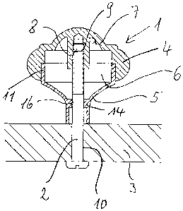
A knob (1) for furniture exhibits a knob top (4), on the under side of which a
separate knob base
(5) protrudes. The knob top (4) and the knob base (5) are concentric and
enclose an interior
hollow space (6). A threaded hole (9) is formed in a central protrusion (8) of
the inner wall (7) of
the knob top (4). A securing screw (2) extends through a central hole (16) of
the knob base (5)
and is screwed into the threaded hole (9).


Claims

Note: Claims are shown in the official language in which they were submitted.

claims
1. Knob for furniture with a knob top, on the underside of which a knob base
protrudes and with
an open threaded hole on its underside to accommodate a securing screw,
characterized in that
the knob top (4) and the knob base (5) are separate concentric components
enclosing an interior
space (6), that the threaded hole (9) is formed in a central protrusion (8) of
the inner wall (7) of
the knob top and that the knob base (5) exhibits a central hole (18) through
which the securing
screw (2) extends.
2. Knob in accordance with Claim 1, characterized in that the knob base (5)
exhibits an upper
centering edge, centered on a centering surface (13) or the knob top (4).
3. Knob in accordance with Claim 1, characterized in that the upper centering
edge (11) of the
knob base (5) exhibits a cylindrical exterior centering surface (12) which is
surrounded by the
cylindrical centering surface (13) of knob top (4).
4. Knob in accordance with Claim 2, characterized in that the upper centering
edge (11) of knob
base (5) exhibits a cylindrical inner centering surface (17) which is
accommodated by a cylindrical
outer centering surface (18) of knob top (4).
5. Knob in accordance with one of Claims 1-4, characterized in that the knob
base (5) is made as
a thin-walled rotationally symmetrical hollow part and that a transverse wall
(14) contains the
central hole (16) for the securing screw (2).

Description

Note: Descriptions are shown in the official language in which they were submitted.


CA 02534002 2006-O1-25
Ref: 115-3146-U LAU 5090 P
Horst Lautenschlager
Knob for furniture
The invention concerns a knob for furniture with a knob, on the underside of
which there
protrudes a knob base, and with an open threaded hole on the underside to
accommodate a
securing screw.
Knobs of this sort have long been known in various designs. They are
particularly used on
furniture for drawers and furniture doors and serve to move the furniture
parts to which they are
attached. Frequently the knob base is designed narrower than the upper part of
the knob as
described here. This facilitates the user exerting tension on the knob because
the user can grip
the knob, which is broader than the base.
Known knobs of this type are made out of one piece of solid material. This
results in a relatively
high requirement for materials. For aesthetic reasons many different designs
of knobs are
desired. For each of these designs a special manufacturing mold, for example
an injection die,
must be prepared for the entire knob. The expense required for this is
considerable.
It is the goat of the invention to produce a knob of the type mentioned above
that can be
produced with a small requirement for material and in which various designs
can be
manufactured at a reduced cost of manufacture.
These goals are achieved by the invention in that the knob and the base are
separate
components, having a common center and surrounding an inner space, in that the
threaded hole
is formed in a central protuberance on the inner wall of the knob and that the
knob base exhibits a
centered hole through which the fastening screw extends.
The two-part design of the knob makes it possible to combine knob bases
readily produced in
large numbers with various knob tops. These various knob tops are
significantly smaller than the
entire knob and thus can be produced at smaller expense than one-piece knobs.
By joining the knob top with the knob base, a relatively larger hollow knob
can be produced so
that the material requirements for the knob are significantly reduced in
comparison to a one-piece
solid design. Because the fastening screw is screwed into the knob top, a
connection is thus
established between the knob top and the knob base without any extra
connection means
required.
Despite the relatively long length of the securing screw, good centering of
the knob top is
accomplished in assembly because the securing screw is already centered in the
knob base.
Therefore even relatively long, slender securing screws can be used.
The knob base can be made as a thin-walled, rotationally symmetrical hollow
piece without
affecting the function or the appearance of the knob top provided that the
transverse wall has a
central hole for the securing screw. Such a thin-wall component can be
manufactured with low
material and manufacturing costs.
A preferred embodiment of the invention provides that the knob base exhibits
an upper centering
edge, which is centered upon a centering surtace of the knob top. This
prevents in a simple way a
relative displacement of the knob top and the knob base.
Further advantageous embodiments of the idea of the invention are the object
of further sub-
claims.
The invention will be described in exemplary embodiments shown in the
drawings. These show:

CA 02534002 2006-O1-25
Ref 115-3146-U LAU 5090 P
Fig. 1 longitudinal section through a furniture past with an attached knob,
Fig. 2 the parts of the knob in Fig.1 in an exploded representation.
Fig. 3 a view in the direction of arrow 111 in Fig. 2,
Figs. 4 and 5 modified embodiments of the knob base and
Figs. &9 modified embodiments of the knob top in section.
The knob 1 shown in Figs.1~3 is attached by means of a securing screw 2 on a
furniture part 3,
for example, a front face of a furniture drawer. Knob 1 is made in two pieces.
It exhibits a knob
top 4 on the underside of which protrudes a knob base 5. The knob top 4 and
the knob base 5
are mutually centered. They endose a hollow knob interior space 6.
A threaded hole 9, made as a blind fide, is located in an essentially
cylindrical protrusion 8
extending downward from an upper inner wall 7 of knob top 4. Securing screw 2
extends outward
from the interior of the drawer through hole 10 and is screwed into threaded
hole 9.
The thin-wall, rotationally symmetrical, chakae-shaped knob base 5 exhibits an
upper centering
edge 11, the cylindrical centering surface 12 of which is accommodated by a
cylindrical centering
surface 13 of knob top 4.
A Uansverse wall 14 in knob base 5, located a short distance above the lower
exterior face 15 of
knob base 5, e~fiibits a central centering hole 16 through which securing
screw 12 extends and is
thereby centered when the knob is assembled (Fig.1).
The modified embodiments of the centering base 5 shown in Figs. 4 and 5
essentially differ only
in their outer contour. Both knobs bases 5 are constricted in the vicinity of
transverse wall 14 and
expand downward to their lower side.
AN knob bases 5 shown exhibit an upper centering edge 11 with the centering
exterior surtace 12
already descxi~d, which surface is centered on a corresponding cylindrical
centering inner
surface t 3 of each of the knob tops 4. In Figs. 6, 8 and 9 it is indicated
that the knob tops may
exhibit very different exterior contours with each having such an internal
centering surface 13.
The upper centering edge 11 on knob base 5 in all of the embodiments
represented also exhibit a
cylindrical inner centering surtace 1T that can accommodate an external
cylindrical centering
surtace 18 of the knob top 4 as shown in Fig. T.
Thus, all of the knob tops 4 shovm in figs. 1-3 and 6-9, varying in their
exterior shapes, can be
freely combined with a8 of the knobs bases 5 shown in Figs. 1, 2 and 4, 5.
The knob taps 4 shown in Figs. 8-9 exhibit radial ribs 19, by means of which
an interior stiffening
of knob top 5 is achieved so that it can be made relatively thin-walled.

Representative Drawing
A single figure which represents the drawing illustrating the invention.
Administrative Status

2024-08-01:As part of the Next Generation Patents (NGP) transition, the Canadian Patents Database (CPD) now contains a more detailed Event History, which replicates the Event Log of our new back-office solution.

Please note that "Inactive:" events refers to events no longer in use in our new back-office solution.

For a clearer understanding of the status of the application/patent presented on this page, the site Disclaimer , as well as the definitions for Patent , Event History , Maintenance Fee  and Payment History  should be consulted.

Event History

Description Date
Application Not Reinstated by Deadline 2009-09-08
Inactive: Dead - No reply to s.30(2) Rules requisition 2009-09-08
Deemed Abandoned - Failure to Respond to Maintenance Fee Notice 2009-01-26
Inactive: Abandoned - No reply to s.30(2) Rules requisition 2008-09-08
Inactive: S.30(2) Rules - Examiner requisition 2008-03-07
Letter Sent 2007-03-29
Inactive: Single transfer 2007-02-15
Correct Applicant Request Received 2007-02-15
Application Published (Open to Public Inspection) 2006-07-26
Inactive: Cover page published 2006-07-25
Inactive: IPC assigned 2006-06-29
Inactive: First IPC assigned 2006-06-23
Inactive: IPC assigned 2006-06-23
Inactive: Courtesy letter - Evidence 2006-02-28
Inactive: Filing certificate - RFE (English) 2006-02-22
Filing Requirements Determined Compliant 2006-02-22
Letter Sent 2006-02-22
Application Received - Regular National 2006-02-22
Request for Examination Requirements Determined Compliant 2006-01-25
All Requirements for Examination Determined Compliant 2006-01-25

Abandonment History

Abandonment Date Reason Reinstatement Date
2009-01-26

Maintenance Fee

The last payment was received on 2007-12-13

Note : If the full payment has not been received on or before the date indicated, a further fee may be required which may be one of the following

  • the reinstatement fee;
  • the late payment fee; or
  • additional fee to reverse deemed expiry.

Please refer to the CIPO Patent Fees web page to see all current fee amounts.

Fee History

Fee Type Anniversary Year Due Date Paid Date
Request for examination - standard 2006-01-25
Application fee - standard 2006-01-25
Registration of a document 2007-02-15
MF (application, 2nd anniv.) - standard 02 2008-01-25 2007-12-13
Owners on Record

Note: Records showing the ownership history in alphabetical order.

Current Owners on Record
LIBERTY HARDWARE MFG. CORP.
Past Owners on Record
CHRISTOPHER D. WOLFE
EARL DAVID FORREST
HORST LAUTENSCHLAGER
Past Owners that do not appear in the "Owners on Record" listing will appear in other documentation within the application.
Documents

To view selected files, please enter reCAPTCHA code :


To view images, click a link in the Document Description column. To download the documents, select one or more checkboxes in the first column and then click the "Download Selected in PDF format (Zip Archive)" or the "Download Selected as Single PDF" button.

List of published and non-published patent-specific documents on the CPD .

If you have any difficulty accessing content, you can call the Client Service Centre at 1-866-997-1936 or send them an e-mail at CIPO Client Service Centre.


Document
Description 
Date
(yyyy-mm-dd) 
Number of pages   Size of Image (KB) 
Description 2006-01-25 2 121
Abstract 2006-01-25 1 10
Claims 2006-01-25 1 30
Drawings 2006-01-25 2 44
Representative drawing 2006-06-30 1 9
Cover Page 2006-07-18 1 33
Acknowledgement of Request for Examination 2006-02-22 1 177
Filing Certificate (English) 2006-02-22 1 158
Request for evidence or missing transfer 2007-01-29 1 102
Courtesy - Certificate of registration (related document(s)) 2007-03-29 1 105
Reminder of maintenance fee due 2007-09-26 1 114
Courtesy - Abandonment Letter (R30(2)) 2008-12-15 1 166
Courtesy - Abandonment Letter (Maintenance Fee) 2009-03-23 1 172
Correspondence 2006-02-22 1 25
Correspondence 2007-02-15 2 63