Language selection

Search

Patent 2534103 Summary

Third-party information liability

Some of the information on this Web page has been provided by external sources. The Government of Canada is not responsible for the accuracy, reliability or currency of the information supplied by external sources. Users wishing to rely upon this information should consult directly with the source of the information. Content provided by external sources is not subject to official languages, privacy and accessibility requirements.

Claims and Abstract availability

Any discrepancies in the text and image of the Claims and Abstract are due to differing posting times. Text of the Claims and Abstract are posted:

  • At the time the application is open to public inspection;
  • At the time of issue of the patent (grant).
(12) Patent Application: (11) CA 2534103
(54) English Title: BONE SEPARATOR
(54) French Title: ECARTEUR A OS
Status: Deemed Abandoned and Beyond the Period of Reinstatement - Pending Response to Notice of Disregarded Communication
Bibliographic Data
(51) International Patent Classification (IPC):
  • A61B 17/02 (2006.01)
  • A61B 17/88 (2006.01)
(72) Inventors :
  • KELLER, ARNOLD (Germany)
(73) Owners :
  • CERVITECH, INC.
(71) Applicants :
  • CERVITECH, INC. (United States of America)
(74) Agent: MARKS & CLERK
(74) Associate agent:
(45) Issued:
(86) PCT Filing Date: 2005-04-05
(87) Open to Public Inspection: 2005-10-27
Availability of licence: N/A
Dedicated to the Public: N/A
(25) Language of filing: English

Patent Cooperation Treaty (PCT): Yes
(86) PCT Filing Number: PCT/EP2005/003576
(87) International Publication Number: WO 2005099589
(85) National Entry: 2006-01-27

(30) Application Priority Data:
Application No. Country/Territory Date
10 2004 018 872.6 (Germany) 2004-04-19

Abstracts

English Abstract


The invention relates to a bone separator, comprising two tubular pin housings
(7), connected by a parallel guide and two pins (13) for connection to the
bone pieces for separation. According to the invention, a greater relative
positional security for the bone pieces for separation may be achieved,
whereby at least one pin housing (7) is provided with a stop device (12) for a
pin (13) located in the pin housing (7). The above comprises a stop finger
(12), moving tangentially to the pin housing (7), engaging in a transverse
groove (14) of the corresponding pin (13) in the stop position, which can be
embodied by a hook, mounted such as to pivot.


French Abstract

L'invention concerne un écarteur à os qui comprend deux logements de broche tubulaires (7), reliés entre eux par une coulisse à déplacement parallèle, ainsi que deux broches (13) à relier aux parties d'os à écarter. L'invention vise à garantir une plus grande sûreté de position l'une par rapport à l'autre aux parties d'os à écarter. A cet effet, au moins un logement de broche (7) est pourvu d'un dispositif d'arrêt (12) pour une broche (13) se trouvant dans le logement de broche (7). Ce dispositif d'arrêt comprend un doigt d'arrêt (12) qui peut être déplacé tangentiellement par rapport au logement de broche (7), qui s'engrène en position d'arrêt dans une rainure transversale (14) de la broche correspondante (13) et qui peut être formé par un crochet logé pivotant.

Claims

Note: Claims are shown in the official language in which they were submitted.

-5-
claims
1. A bone spreader, comprising two tubular pin holders
(7) which are connected to one another by a parallel
guide system (1, 4, 5) and are intended for two pins
(13) to be connected to the bone parts that are to be
spread apart, at least one pin holder (7) having a
locking device (12, 14) for a pin (13) located
therein, characterized in that the pins (13) have at
least one transverse groove (14) and the locking de-
vice is composed of a locking finger (12) which is
guided between a locking position and a release posi-
tion in a transverse movement tangentially with re-
spect to the pin holder (7).
2. The bone spreader as claimed in claim 1, characterized
in that the locking finger (12) is designed as a hook
which is mounted at the open end of the pin holder (7)
closer to the parallel guide system and is pivotable
about an axis extending approximately parallel to said
pin holder (7).

Description

Note: Descriptions are shown in the official language in which they were submitted.


CA 02534103 2006-O1-27
Cervitech, Inc.
CERT039PW0
D/fi
Boae separator
The invention relates to a bone spreader of the type speci-
fied in the preamble of claim 1 and comprising two parallel
tubular pin holders, which are connected to one another by
a parallel guide system, and two pins to be connected to
the bone parts that are to be spread apart. In connection
with the invention, this term also includes screws. The
pins are introduced parallel to one another into the bone
parts that are to be spread apart. Their free sections are
introduced into the pin holders. When these are now moved
away from one another or moved closer to one another by
means of the parallel guide system, this movement is trans-
mitted to the bone parts. This type of spreader is espe-
cially suitable for distraction of two cervical vertebral
bodies for the purpose of implantation of a cervical in-
tervertebral prosthesis, as the vertebral bodies are guided
parallel to one another during the distraction. However,
this parallel attribute applies only with respect to the
direction of the pin holders. Two degrees of freedom re-
main. These are, on the one hand, a rotation of the bone
parts about the pin axis, which for various reasons is of
no consequence in normal circumstances, and, on the other
hand, a displacement in the direction of the pin holders,
which displacement can be prevented by a locking device
known in the form of a screw connection, which is awkward
to use.
According to the invention, this disadvantage is remedied
by the fact that the locking device is designed as a quick-
coupling, namely in the form of a locking finger which is
guided between a locking position and a release position in

' CA 02534103 2006-O1-27
- 2 -
a transverse movement tangentially with respect to the pin
holder and at least one transverse groove in the pin, into
which groove the locking finger engages in the locking po-
sition. Several transverse grooves may also be provided,
one of which is chosen for the engagement of the locking
finger. To ensure that the locking finger cannot be lost as
a separate part, according to a further feature of the in-
vention, it is designed as a hook which is mounted so as to
be pivotable about an axis extending approximately parallel
to the pin holder. The arrangement is especially simple and
clear if the hook is arranged at the open end of the pin
holder closer to the parallel guide system.
The invention is explained in more detail below with refer-
ence to the drawing which depicts an advantageous illustra-
tive embodiment and in which:
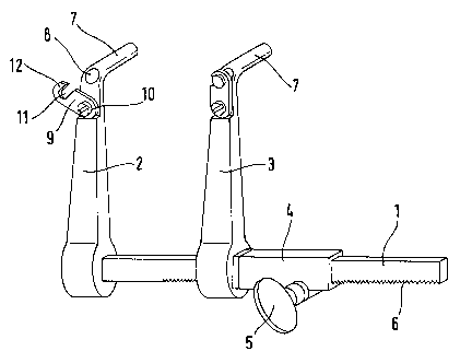
Fig. 1 shows an overall view of the spreader, and
Figs 2 and 3 show partial views of the spreader in dif-
ferent stages of its operation.
A first spreader body 2 is arranged rigidly at the end of a
guide bar 1 of noncircular cross section. A second spreader
body 3 with a guide tube 4 is arranged parallel to the
spreader body 2 on the guide bar 1 and is displaceable in
the longitudinal direction of said guide bar 1, but not ro-
tatable. The displacement is effected using a toggle 5
which is connected to a pinion (not shown) engaging in a
toothing 6 of the guide bar 1. In addition, any kind of
locking means can be connected to the spreader body 3 or to
the guide tube 4 so as to secure the distance between the
spreader bodies 2 and 3.

~
CA 02534103 2006-O1-27
- 3 -
Arranged at the free ends of the spreader bodies 2 and 3
there are tubular pin holders 7 which are set at an angle
in relation to the spreader bodies 2, 3. They extend paral-
lel to one another in planes which are perpendicular to the
guide bar. They are used for receiving two pins, each one
of which is connected respectively to one of the two bones
or fragments that are to be distracted. By operating the
toggle 5, it is possible for these bone parts or fragments
to be spread apart from one another or guided toward one
another, in which process they are held parallel to one an-
other in relation to the axes of the two pin holders 7. To
this extent, the bone spreader can be regarded as being
known.
Whereas in known bone spreaders of this kind the hole in-
side the pin holder is closed at the rear end connected to
the associated spreader body 2, 3, according to the inven-
tion, it is continued right through at this location, such
that it opens out at 8. Adjacent to the opening 8, a hook
plate 9 is mounted pivotably by way of a screw 10. It lies
in a plane extending substantially perpendicular to the
axis of the pin holder. It contains a hook cutout 11 which
is outwardly delimited by a hook finger 12 whose direction
extends tangentially with respect to the axis of the pin
holder.
The associated pins 13 have, at least at their rear end,
one or more peripheral grooves 14 whose width (measured in
the longitudinal direction of the pin) is slightly greater
than the thickness of the plate 9 or hook finger 12. When a
pin is located in the pin holder in such a way that its
rear end protrudes outward at the rear, as is shown in Fig.
2, the plate 9 can be pivoted in such a way that the hook
finger 12 engages in one of the grooves 14 and in this po-

CA 02534103 2006-O1-27
- 4 -
sition, which is illustrated in Fig. 3, prevents the pin 13
from moving in its longitudinal direction.
The hook finger 12 can be designed such that it locks in
the closed position (Figures 1 and 3) so as not to inadver-
tently come loose from here under the action of slight
forces. Instead of this, or in addition, the pivot bearing
of the plate 9 can be provided with a spring or catch
mechanism which satisfies this purpose.
The invention has the effect that the pins received in the
pin holders 7 can be secured in the pin holder by means of
a rapid and simple movement by the operator. In this way,
the secured bone parts are prevented from executing a rela-
tive movement in the direction of the pin holders.

Representative Drawing
A single figure which represents the drawing illustrating the invention.
Administrative Status

2024-08-01:As part of the Next Generation Patents (NGP) transition, the Canadian Patents Database (CPD) now contains a more detailed Event History, which replicates the Event Log of our new back-office solution.

Please note that "Inactive:" events refers to events no longer in use in our new back-office solution.

For a clearer understanding of the status of the application/patent presented on this page, the site Disclaimer , as well as the definitions for Patent , Event History , Maintenance Fee  and Payment History  should be consulted.

Event History

Description Date
Application Not Reinstated by Deadline 2011-04-05
Time Limit for Reversal Expired 2011-04-05
Inactive: Abandon-RFE+Late fee unpaid-Correspondence sent 2010-04-06
Deemed Abandoned - Failure to Respond to Maintenance Fee Notice 2010-04-06
Inactive: Correspondence - Transfer 2009-06-30
Letter Sent 2006-11-06
Inactive: Single transfer 2006-09-14
Inactive: Cover page published 2006-03-28
Inactive: Courtesy letter - Evidence 2006-03-28
Inactive: Notice - National entry - No RFE 2006-03-24
Application Received - PCT 2006-02-22
National Entry Requirements Determined Compliant 2006-01-27
Application Published (Open to Public Inspection) 2005-10-27

Abandonment History

Abandonment Date Reason Reinstatement Date
2010-04-06

Maintenance Fee

The last payment was received on 2009-03-26

Note : If the full payment has not been received on or before the date indicated, a further fee may be required which may be one of the following

  • the reinstatement fee;
  • the late payment fee; or
  • additional fee to reverse deemed expiry.

Please refer to the CIPO Patent Fees web page to see all current fee amounts.

Fee History

Fee Type Anniversary Year Due Date Paid Date
MF (application, 2nd anniv.) - standard 02 2007-04-05 2006-01-27
Basic national fee - standard 2006-01-27
Registration of a document 2006-09-14
MF (application, 3rd anniv.) - standard 03 2008-04-07 2008-03-26
MF (application, 4th anniv.) - standard 04 2009-04-06 2009-03-26
Owners on Record

Note: Records showing the ownership history in alphabetical order.

Current Owners on Record
CERVITECH, INC.
Past Owners on Record
ARNOLD KELLER
Past Owners that do not appear in the "Owners on Record" listing will appear in other documentation within the application.
Documents

To view selected files, please enter reCAPTCHA code :


To view images, click a link in the Document Description column. To download the documents, select one or more checkboxes in the first column and then click the "Download Selected in PDF format (Zip Archive)" or the "Download Selected as Single PDF" button.

List of published and non-published patent-specific documents on the CPD .

If you have any difficulty accessing content, you can call the Client Service Centre at 1-866-997-1936 or send them an e-mail at CIPO Client Service Centre.


Document
Description 
Date
(yyyy-mm-dd) 
Number of pages   Size of Image (KB) 
Abstract 2006-01-27 1 18
Drawings 2006-01-27 1 17
Representative drawing 2006-01-27 1 7
Claims 2006-01-27 1 24
Description 2006-01-27 4 148
Cover Page 2006-03-28 1 37
Notice of National Entry 2006-03-24 1 206
Courtesy - Certificate of registration (related document(s)) 2006-11-06 1 105
Reminder - Request for Examination 2009-12-08 1 117
Courtesy - Abandonment Letter (Maintenance Fee) 2010-06-01 1 173
Courtesy - Abandonment Letter (Request for Examination) 2010-07-13 1 164
PCT 2006-01-27 6 238
Correspondence 2006-03-24 1 25