Note: Descriptions are shown in the official language in which they were submitted.
CA 02534182 2006-01-27
2
BACKGROUND OF THE INVENTION
(a) Technical Field of the Invention
The present invention generally relates the pump device for fluid
dispensers, and more particular to a pump device having partitioned rooms for
air and fluid separately.
(b) Description of the Prior Art
Fluid dispensers are coinmonly found in the household kitchens and
bathrooms for holding liquid soaps and detergents, shampoo and conditioners,
hand and body lotions, etc. A fluid dispenser usually contains a fluid
container device and a pump device mounted on top of the container device.
A conventional pump device is shown in FIG 1.
As illustrated, the conventional pump device mainly contains a spout A l,
a hollow actuating rod A2 attached to the bottom of the spout A 1, a fastening
element A3 for locking the spout A1 when the pump device is not in use, a
closure cap A4 for locking the pump device to the container device (not
shown), a hollow chamber A5, a plug element A7 attached to the bottom of
the actuating rod A2 via an intermediate hollow rod A7 1, a piston element A6
wrapping around the rod A71 positioned on top of the plug element A7 having
air-tight contact with the inner wall of the chainber A5, a spring A8, a ball
valve A9, and a dip tube A10. The operation of the pump device is as
CA 02534182 2006-01-27
3
follows. When the spout A 1 is pushed downward, the plug element A7
compresses the spring A8 and the piston element A6 drives the air in the
chamber A5 downward, forcing the ball valve A9 to block the dip tube A 10.
When the pressure on the spout A 1 is released, the plug element A7 and the
piston element A6 ai-e automatically restored to their original position by
the
spring A8. In the mean time, the air in the chamber A5 is expelled through a
number of ventilation holes A51 configured on the top wall of the chamber A5,
thereby vacuuming the space inside the chamber A5. The fluid stored in the
container device is therefore sucked into the dip tube A 10, pushes the ball
valve A9 aside, and flows into the chamberA5. When the spoutAl is
pushed again, the descending of the piston element A6 forces the fluid inside
the chamber A5 to flow into a through hole A72 on the rod A71 between the
piston element A6 and the plug element A7, through the actuating rod A2, and
then out from the spout Al.
Please note that, when the plug element A7 and the piston element A6 are
pushed down, the friction between the piston element A6 and the inner wall of
the chamber A5 causes a tiny gap developed between the piston element A6
and the plug element A7, thereby exposing the through hole A72. As the ball
valve A9 blocks the dip tube A10 under air pressure, only the fluid in the
chamber A5 will flow through the through hole A72. On the other hand,
CA 02534182 2006-01-27
4
when the plug element A7 and the piston element A6 are restored as the spring
A8 expands, the friction between the piston element A6 and the inner wall of
the chamber A5 causes the plug element A7 and the piston element A6 to
tightly attach to each other, thereby closing the through hole A72 and
prohibiting the fluid to pass through. In the mean time, the fluid in the
container device is sucked into the chamber A5 to make up the amount of
fluid dispensed in the previous stroke.
The foregoing conventional pump device has a number of shortcomings.
First of all, as the fluid to be dispensed is stored inside the chamber,
various
components of the pump device are completely immersed in the fluid. These
components will quickly deteriorate from the erosion of the fluid, resulting
in
short operation life. Especially for metallic components such as the spring,
they will even engage in chemical reaction with the fluid, thereby altering
the
quality and property of the fluid.
Secondly, as the fluid has to be pumped into the chamber via narrow dip
tube and again through the actuating rod, the viscosity of the fluid
significantly
affects the operation of the pump device. For highly viscous fluid, a user has
to exei-t additional force to obtain an appropriate amount of the fluid in a
longer period of time. In other words, there is a notable hysteresis
phenomenon for both the application of force and the response of the pump
CA 02534182 2006-01-27
device.
Thirdly, the same hysteresis problem would also lead to the fluid's
continuous dripping from the spout after dispensing as the highly viscous
fluid
gradually releases its pressure, resulting in user dissatisfaction.
5 In addition, as the ball valve is the only device blocking the contact of
the
fluid inside the container device with outside air and the ball valve can
freely
move inside the chamber, the fluid's continuous exposure to outside air is
inevitable and the conventional pump device is therefore not appropriate for
highly volatile fluid.
CA 02534182 2006-01-27
6
SUMMARY OF THE INVENTION
The primary purpose of the present invention is to provides a novel
structure for the pump device of fluid dispensers to obviate the foregoing
shortcomings of prior approaches.
The major characteristic of the present invention is that the chamber of
the pump device is partitioned into a pressure room and a fluid room. A
piston element is engaged inside the pressure room by an actuating rod to push
the piston element downward, or by a resilient element beneath the piston
element to i-estore the piston element back to the top. An air valve element
at
the bottom of the piston element automatically opens or closes the induction
of
air to the pressure room when the piston element is moved upward or
downward. As such, air pressure is reliably applied to the fluid in the
container device as the air flows from the chamber into the container device
via an outlet hole therebetween.
The fluid room is dedicated to the passage of the fluid. A normally
closed fluid valve element is provided at the bottom of the fluid room. When
the fluid in the container device is pressurized, the fluid pushes open the
fluid
valve element, flows into the fluid room and then out of the spout of the pump
device.
Compared to the prior arts, the proposed pump device has quite a few
CA 02534182 2006-01-27
7
advantages. Except when the fluid is discharged, the air valve element and
the normally closed fluid valve element seals the container device at all
time,
avoiding volatile fluid to evaporate. Additionally, the separation of pressure
room and the fluid room avoids the erosion and deterioration of the
components as often found in prior arts resulted from their direct contact
with
and immersion within the fluid, thereby lengthening the operation life of the
pump device considerably. Further more, according to the present invention,
the air pressure is dir-ectly applied to the fluid to drive them out of the
container device via a shorter passageway, in contrast to the prior approaches
which sucks the fluid out through a longer passageway. The present
invention is therefore more responsive to the user operation, requires less
user
effort, and does not llave the dripping problem, even for fluid of high
viscosity.
The foregoing object and summaiy provide only a brief introduction to
the present invention. To fully appreciate these and other objects of the
present invention as well as the invention itself, all of which will become
apparent to those skilled in the art, the following detailed description of
the
invention and the claims should be read in conjunction with the accompanying
drawings. Tlu=oughout the specification and drawings identical reference
numerals refer to identical or similar parts.
Many other advantages and features of the present invention will become
CA 02534182 2006-01-27
8
manifest to those versed in the art upon making reference to the detailed
description and the accompanying sheets of drawings in which a preferred
structural embodiment incorporating the principles of the present invention is
shown by way of illustrative exainple.
CA 02534182 2006-01-27
9
BRIEF DESCRIPTION OF THE DRAWINGS
FIG. 1 is a sectional view showing a conventional putnp device.
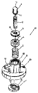
FIG, 2 is a perspective view showing the appearance of a pump device
according to an embodiment of the present invention.
FIG. 3 is a perspective exploded view showing the various components of
the pump device of FIG 2.
FIG 4 is a sectional view showing the pump device of FIG 2.
FIG. 5 contains the top and sectional views showing the fluid valve
element of the pump device of FIG 2.
FIG 6 is a sectional view showing another embodiment of the piston
element of the present invention.
FIG 7 is a sectional view showing the operation scenario of the pump
device of FIG. 2.
FIG 8 is a sectional view showing an application of the pump device of
FIG 2.
FIG. 9 is a sectional view showing another application of the pump device
of FIG. 2.
CA 02534182 2006-01-27
DETAILED DESCRIPTION OF THE PREFERRED EMBODIMENTS
The following descriptions are of exemplary embodiments only, and are
not intended to limit the scope, applicability or configuration of the
invention
in any way. Rathei-, the following description provides a convenient
5 illustration for implementing exemplary embodiments of the invention.
Uarious changes to the described embodiments may be made in the function
and aiTangement of the elements described without departing from the scope
of the invention as set for-th in the appended claims.
Please refer to FIGS. 2 and 3. As illustrated, a pump device 10
10 according to an embodiment of the present invention mainly contains a head
element 1, an actuating rod 2, a fastening element 3, a piston element 4, a
resilient element 5, a body member 6, and a fluid valve element 7. The head
element 1 is provided on the top end of the actuating rod 2, and a screw
thread
11 is configured around the bottom portion of the head element 1. A
corresponding screw thread 31 is configured around the inner wall of the
ruzg-shaped fastening element 3 so that, when the pump device is not in use,
the head element 1 can be screwed into the fastening element 3. The other
end of the actuating rod 2 is embedded inside a through hole 41 in the center
of the piston element 4. The head element 1, the actuating rod 2, and the
piston element 4 therefore can be engaged in vertical movement together.
CA 02534182 2006-01-27
11
The body member 6 has a hollow chamber 62 configured on top of an
enclosure cap 63 with a discharging spout 61 extended from the outer wall of
the chamber 62. As shown in FICi 4, the chamber 62 is partitioned into two
separate rooms: a pressure room 621 and a fluid room 622. The actuating
rod 2 penetrates into the pressure room 621 via the fastening element 3 which
seals the piston element 4 from the top. The resilient element 5 is positioned
beneath the piston element 4 inside the pressure room 621. At the bottom of
the through hole 41 of the piston element 4, an air valve element 42 is
provided that will be opened and closed synchronously with the up and down
movement of piston element 4, thereby achieving the air induction and
exhaust for the pressure room 621.
Please also refel- to FIG 7. An air duct 12 is provided all the way from
the head element 1 to the bottom of the actuating rod 2, connecting to the
through hole 41 of the piston element 4. When the piston element 4 moves
downward by pushing the head element 1, the air valve element 42
automatically closes the through hole 42 and the air inside the pressure room
621 is expelled through an outlet hole 6211 configured around the bottom of
the pressure room 62 1. On the other hand, when the pressure on the head
element 1 is released and the piston element 4 is raised upward by the
resilient
element 5, the air valve element 42 automatically opens the through hole 42
CA 02534182 2006-01-27
12
and air is drawn into the pressure room 621 via the air duct 12.
The fluid valve element 7 is fixedly positioned at the bottom of the body
member 6, sealing the fluid room 622 from the bottom. As shown in FIG 5,
the fluid valve element 7 has a valve body 71 and a valve lid 72. The valve
lid 72 is attached to the valve body 71 which has a through hole 712 in the
center surrounded bv an indented lid seat 711. By flipping the valve lid 72
toward the valve body 71, the valve lid 72 will fit inside the lid seat 711
and
seal the through hole 712. As shown in FIG 8 in which the pump device 10
is tightly installed on a container device B by the enclosure cap 63, the
inner
pressure inside the container device B is increased when the piston element 4
is pushed downward and the air in the pressure room 621 is forced into the
container device B via the outlet hole 6211. The fluid C inside the container
device B, therefore, is forced into the dip tube D, pushes open the valve lid
72,
enters into the fluid i-oom 622, and then flows out from the discharge spout
61.
Please note that a positioning element 6221 provided inside the fluid room 622
appropriately presses the folded section of the valve lid 72 so that the valve
lid
72 normally closes the through hole 712 of the fluid valve element 7 at all
times.
As shown in FIG 9 which is another application of the present invention,
the fluid C is stored in a storage member B 1 inside the container device B.
CA 02534182 2006-01-27
13
The lower portion of the storage member B 1 (i.e., the portion close to the
bottom of the container device B) is flexible, and the body member 6 of the
pump device 10 is fixedly joined to the opening of the storage member B 1 on
the top. As such, as air is pumped into the container device B, the fluid C in
the storage member B I is 'squeezed' out of the storage member B 1 literally.
According to the spirit of the present invention, another embodiment of
the piston element 4 is shown in FIC'z 6, in which the body of the piston
element 4 is surrounded with a number of washer rings 40 to provide
improved air-tightness as the piston element 4 is moved inside the pressure
room 621.
It will be understood that each of the elements described above, or two or
more together may also find a useful application in other types of methods
differing from the type described above.
While certain novel features of this invention have been shown and
described and are pointed out in the annexed claim, it is not intended to be
limited to the details above, since it will be understood that various
omissions,
modifications, substitutions and changes in the forms and details of the
device
illustrated and in its operation can be made by those skilled in the art
without
departing in any wa~~ fi om the spirit of the present invention.