Note: Descriptions are shown in the official language in which they were submitted.
CA 02534223 2006-01-26
913/42048/343
PATENT
SAW TOOL
BACKGROUND OF THE INVENTION
This invention is generally directed to a tool which has a saw blade removable
attached thereto. The saw blade can be easily detached from the tool without
the use
of a screwdriver. The saw blade can be extended for use, or retracted when not
in use
for safe storage.
Most prior art saw tools, such as the one disclosed in United States Patent
No.
4,660,284, have a saw blade attached within a frame comprised of two parts.
The two
parts and the saw blade are secured together by a screw that extends
therethrough. To
release the saw blade when it becomes worn or if a different type of saw blade
is to be
used, the user must use a screwdriver to remove the screw, before the saw
blade can
be removed from the frame. This increases the amount of work required in the
field,
as well as requires another tool.
United States Patent No. 6,789,326 discloses a saw tool which does not
require the use of an outside tool, such as a screwdriver, to release the saw
blade
which is held within a frame comprised of two parts. The frame includes a
slider
which is held within a locking member by two bars. The frame can be slid along
the
length of the tool to extend the saw blade for use, or to retract the saw
blade for
1
CA 02534223 2011-01-24
63632-1636
storage. The saw blade is sandwiched between the slider and the locking
member. The locking member has a blade holder, which takes the form of a
protrusion, mounted on a deflectable arm. The arm is deflected by pressing a
press block on the locking member. The saw blade can be released anywhere
along the length of the travel of the frame. Because the slider and the press
block
are adjacent to each other and because the saw blade can be released anywhere
along the length of the travel of the frame, this may lead to the undesirable
release
of the saw blade if the press block is accidentally pressed during use of the
tool.
The present invention provides a saw tool which overcomes the
problems presented in the prior art and which provides additional advantages
over
the prior art, such advantages will become clear upon a reading of the
attached
specification in combination with a study of the drawings.
SUMMARY OF THE INVENTION
Some embodiments of the present invention is generally directed to
a tool which has a saw blade removable attached thereto. The saw blade can be
easily detached from the tool without the use of another tool, such as a
screwdriver. The saw blade can be extended for use, or retracted when not in
use
for safe storage. A spare blade holder is provided and be accessed without the
use of another tool, such as a screwdriver.
According to one aspect of the present invention, there is provided a
tool into which a saw blade can be mounted and removed therefrom, said tool
comprising: a housing, said housing have a groove defined therein; an
attachment
assembly mounted in said groove in said housing, said attachment assembly
being capable of sliding within said groove relative to said housing, said
attachment assembly including a first part, a second part, and a member
attaching
said second part to said first part while allowing said second part to move
relative
to said first part, wherein the saw blade can be inserted between said first
and
second parts so that the saw blade is sandwiched between said first and second
parts, the saw blade being removable therefrom; and a spring retainer affixed
within said housing, said spring retainer capable of being in an undeflected
2
CA 02534223 2011-01-24
63632-1636
condition and a deflected condition, said attachment assembly being moveable
within said housing to abut against said spring retainer, wherein when said
attachment assembly abuts said spring retainer, said second part can be moved
out of engagement with said first part to allow the removal of the saw blade
from
between the first and second parts, said second part engaging against said
spring
retainer and moving said spring retainer into said deflected condition when
said
second part is moved out of engagement with said first part.
According to another aspect of the present invention, there is
provided a tool into which a saw blade can be mounted and removed therefrom,
said tool comprising: a housing, said housing have a groove defined therein;
an
attachment assembly mounted in said groove in said housing, said attachment
assembly being capable of sliding within said groove relative to said housing,
said
attachment assembly including a first part, a second part insertable into an
aperture in said first part, and a member attaching said second part to said
first
part while allowing said second part to move relative to said first part, the
saw
blade being insertable between said first and second parts and removed
therefrom, said second part having a protrusion provided thereon and said
first
part including a recess into which said protrusion is insertable and
releasable
therefrom, and said member including a threaded portion, said member extending
outwardly from said housing; a knob mounted on said threaded portion of said
member and translatable thereon such that said knob can be engaged with said
housing or disengaged from said housing; a spring retainer affixed within said
housing, said spring retainer including a vertical leg attached to said
housing, but
deflectable relative thereto, and an arcuate arm attached to said leg and a
horizontal leg attached thereto and attached to said housing, said attachment
assembly being moveable within said housing to abut against said vertical leg
and
said arcuate arm and to sit on said horizontal leg, wherein when said
attachment
assembly abuts said vertical leg, said second part can be moved out of
engagement with said first part by a user pushing on said member to allow the
removal of the saw blade from between the first and second parts.
2a
CA 02534223 2011-01-24
63632-1636
BRIEF DESCRIPTION OF THE DRAWINGS
The organization and manner of the structure and operation of the
invention, together with further objects and advantages thereof, may best be
understood by reference to the following description, taken in connection with
the
accompanying drawings, wherein like reference numerals identify like elements
in
which:
FIG. 1 is a perspective view of a saw tool which incorporate the
features of the present invention, which has a saw blade attached thereto;
FIG. 2 is a side elevational view of the saw tool;
FIG. 3 is an exploded, perspective view of the saw tool;
2b
CA 02534223 2006-01-26
FIG. 4 is a perspective view of a bottom housing;
FIG. 5 is a top elevational view of a rear portion of the bottom housing;
FIG. 6 is a top elevational view of a front portion of the bottom housing,
with
a spring retainer positioned therein;
FIG. 7 is a top elevational view of a front portion of the bottom housing,
with
the spring retainer removed therefrom;
FIG. 8 is a perspective view of a top housing;
FIG. 9 is a bottom elevational view of the saw tool;
FIG. 10 is a top elevational view of the saw tool;
FIG. 11 is an exploded perspective view of an attachment assembly used to
attach a saw blade, also shown in a perspective view, within the saw tool;
FIG. 12 is a perspective view of the saw blade attached to the attachment
assembly of FIG. 11;
FIG. 13 is a perspective view of a spring retainer;
FIG. 14 is a perspective view of a spare blade holder; and
FIG. 15 a perspective view of the tool, with the top housing removed and the
saw blade attached thereto.
3
CA 02534223 2006-01-26
DETAILED DESCRIPTION OF THE ILLUSTRATED EMBODIMENT
While the invention may be susceptible to embodiment in different forms,
there is shown in the drawings, and herein will be described in detail, a
specific
embodiment with the understanding that the present disclosure is to be
considered an
exemplification of the principles of the invention, and is not intended to
limit the
invention to that as illustrated and described herein.
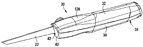
A preferred embodiment of a saw tool 20 is shown in the drawings to which a
saw blade 22 can be attached and removed. The tool 20 includes a housing 24, a
saw
blade sliding and attachment mechanism 26 mounted within the housing 24, and a
spare blade holder 28 mounted within the housing 24. The saw blade sliding and
attachment mechanism 26 provides a quick release for releasing the saw blade
22
therefrom without the use of other tools, such as a screwdriver. The spare
blade
holder 28 provides for replacement saw blades 22' mounted within the housing
24.
The spare blade holder 28 can be released from the housing 24 without the use
of
other tools, such as a screwdriver. The housing 24 includes a lower housing 30
and an
upper housing 32, each formed of plastic.
While lower, upper, front, rear and the like are used in the describing the
tool
20, these descriptors are primarily used for convenience in describing the
invention,
although they do denote the preferred orientation for use of the tool 20.
The lower housing 30 is best shown in FIGS. 4-7. The lower housing 30 has a
base wall 34 and upstanding first and second side walls 36, 38 which extend
therefrom, and a front wall 40 which closes the front ends thereof. A slot 42
is
provided through the front wall 40. The front wall 40 angles outwardly and
upwardly
from the base wall 34.
A rib 40 extends generally perpendicular to the base wall 34 at approximately
the midpoint between the first and second side walls 36, 38. The rib 40
includes a
first section 46 which extends from a point spaced from the front wall 40
towards the
rear of the lower housing 30, a second section 48 which extends from the first
section
46, a third section 50 which extends rearwardly from the second section 48,
and a
4
CA 02534223 2006-01-26
fourth section 52 which extends rearwardly from the third section 50 to a
point which
is spaced a predetermined distance from a rear end of the base wall 34. On the
side of
the rib 44 which faces the first side wall 36, the surfaces of the first,
second and fourth
sections 46, 48, 52 are planar. The surface of the third section 50 which
faces the first
side wall 36 is recessed from the first, second and fourth sections 46, 48,
52, and thus
is further away from the first side wall 36, but is parallel thereto. In
addition, the first
and fourth sections 46, 52 have heights (distance from the base wall 34) which
are
approximately equal. The second and third sections 48, 50 have heights which
are
approximately equal, but are less than the height of the first and fourth
sections 46, 52.
On the side of the rib 44 which faces the second side wall 38, a screw
counterbore 54
is proximate to the second section 48 and a pair of spaced protrusions 56a,
56b extend
from the fourth section 52. Alternatively, a single protrusion may be
provided.
A first groove 58 is provided between the rib 44 and the first side wall 36.
The side walls of the first groove 58 are defined by the rib 44, the first
side wall 36
and the base wall 34. A front end of the first groove 58 is substantially
closed by the
front wall 40, but the first groove 58 opens to the slot 42 in the front wall
40. A rear
end wall 60 of the first groove 58 extends between the first side wall 36 and
the rib
44. Proximate the rear end wall 60, on the side opposite to the first groove
58, a
screw counterbore 62 is provided. The screw counterbore 62 is spaced from the
rear
end of the lower housing 30. As shown in FIG. 7, proximate the front end of
the first
groove 58, a first recess 64 is provided in the base wall 34 and extends
across at least
a portion of the first groove 58 proximate the first section 46. A second
recess 66 is
provided in the base wall 34 and extends across the width of the first groove
58
proximate the juncture of the third section 50 to the fourth section 52.
A second groove 68 is provided between the rib 44 and the second side wall
38. The side walls of the second groove 68 are defined by the rib 44, the
second side
wall 38 and the base wall 34. The screw counterbore 54 is provided at the
front end
of the second groove 68 and forms a front end wall thereof. The rear end of
the
second groove 68 is open to the rear end of the lower housing 30.
5
CA 02534223 2006-01-26
As shown in FIGS. 2 and 4, the upper end of the first side wall 36 has a
reduced height portion 70 which extends along a predetermined length thereof.
The
front end of the reduced height portion 70 generally aligns with the front end
of the
second section 48 of the rib 44. The rear end of the reduced height portion 70
generally aligns with the rear end of the fourth section 52 of the rib 44. A
plurality of
spaced apart arcuate recesses 72a, 72b, 72c, 72d are provided along the length
of the
reduced height portion 70. One such recess 72a is provided at the front end of
the
reduced height portion 70 and another such recess 72d is provided at the rear
end of
the reduced height portion 70. Other such recesses 72b, 72c are spaced along
the
length of the reduced height portion 70. As shown, four such recesses 72a,
72b, 72c,
72d are provided, but it is to be understood that more or fewer may be
provided.
While the recesses 72a, 72b, 72c, 72d are shown as arcuate, other shapes may
be
provided.
As best shown in FIGS. 4 and 5, proximate the rear end of the lower housing
30, a blade capture and release mechanism 74 is provided. The blade capture
and
release mechanism 74 includes a release 76 which is formed in the base wall 34
of the
lower housing 30 and a retaining wall 78 provided on the base wall 34.
The release 76 is formed by providing a generally U-shaped slot 80 in the base
wall 34 to define a tab than can be flexed relative to the remainder of the
base wall 34.
The slot 80 includes a base section 82 and side sections 84a, 84b. The side
sections
84a, 84b are parallel to the side walls 36, 38 of the lower housing 30 and a
rear end of
each side section 84a, 84b is proximate, but spaced a predetermined distance
from, the
rear end of the housing 24. The base section 82 is provided at the front end
of each
side section 84a, 84b and is generally perpendicular to the side sections 84a,
84b. A
cam surface 86 is provided on the release 76 and extends from the rear end of
the
release 76 defined at the rear ends of the side sections 84a, 84b towards the
front end
of the release 76 defined at the base section 82. The cam surface 86 slopes
upwardly
from the rear end of the release 76 to the front end of the release 76 and
away from the
base wall 34.
6
CA 02534223 2006-01-26
The retaining wall 78 is provided on the base wall 34, proximate to the base
section 82 of the slot 80 and extends parallel to the base section 82. The
retaining
wall 78 has a height which is equal to the greatest height of the cam surface
86. A
pocket 88 is defined on the side of the retaining wall 78 opposite to the slot
80. If
desired, side walls 90a, 90b may extend from the retaining wall 78 to further
define
the pocket 88.
As best shown in FIG. 8, the upper housing 32 has a base wall 92 and
upstanding first and second side walls 94, 96 which extend therefrom. The
front ends
of the first and second side walls 94, 96 angle inwardly and downwardly from
the base
wall 92.
A rib 98 extends generally perpendicular to the base wall 92 at approximately
the midpoint between the first and second side walls 94, 96. The rib 98
includes a
first section 100 which extends from the front end of the upper housing 32
towards the
rear end of the upper housing 32, a second section 102 which extends
rearwardly from
the first section 100, and a third section 104 which extends rearwardly from
the
second section 102 to a point which is spaced a predetermined distance from a
rear
end of the base wall 92. On the side of the rib 92 which faces the first side
wall 94,
the surfaces of the sections 100, 102, 104 form a planar surface. The first
and third
sections 100, 104 have a height (distance from the base wall 92) which is
approximately equal, and the second section 1.02 has a height which is less
than the
height of the first and third sections 100, 104. On the side of the rib 92
which faces
the second side wall 96, a pair of spaced protrusions 106a, 106b extend
therefrom.
Alternatively, a single protrusion may be provided.
A first groove 108 is provided between the rib 98 and the first side wall 94.
The side walls of the first groove 108 are defined by the rib 98, the first
side wall 94
and the base wall 92 of the upper housing 32. A front end of the first groove
108 is
open. A rear end wall 110 of the first groove 108 extends between the first
side wall
94 and the rib 98. Proximate the rear end wall 110, on the side opposite to
the first
groove 108, a screw counterbore 112 is provided. The screw counterbore 112 is
7
CA 02534223 2006-01-26
spaced from the rear end of the upper housing 32.
A second groove 114 is provided between the rib 98 and the second side wall
96. The side walls of the second groove 114 are defined by the rib 98, the
second side
wall 98 and the base wall 92 of the upper housing 32. A front end wall 116 of
the
second groove 114 extends between the rib 98 and the second side wall 96.
Proximate the front end wall 116, on the side opposite to the second groove
114, a
screw counterbore 118 is provided. The screw counterbore 118 is spaced from
the
front end of the upper housing 92. The rear end of the second groove 114 is
open to
the rear end of the upper housing 92.
As shown in FIGS. 2 and 8, the lower end of the first side wall 94 has a
reduced height portion 120 which extends along a predetermined length thereof.
The
front end of the reduced height portion 120 generally aligns with the front
end of the
second section 102 of the rib 98. The rear end of the reduced height portion
120
generally aligns with the rear end of the third section 104 of the rib 98. A
plurality of
spaced apart arcuate recesses 122a, 122b, 122c, 122d are provided along the
length of
the reduced height portion 120. One such recess 122a is provided at the front
end of
the reduced height portion 120 and another such recess 122d is provided at the
rear
end of the reduced height portion 120. Other such recesses 122b, 122c are
spaced
along the length of the reduced height portion 120. As shown, four such
recesses
122a, 122b, 122c, 122d are provided, but it is to be understood that more or
fewer
may be provided. While the recesses 122a, 122b, 122c, 122d are shown as
arcuate,
other shapes may be provided.
The lower and upper housings 30, 32 have elastomeric grips 124, 126 provided
thereon. The grips 124, 126 provide a more ergonomic grip and feel to the tool
20
when the tool 20 is being tightly gripped by the user during use.
The lower and upper housings 30, 32 are mated together to form the completed
housing 24 in which the saw blade sliding and attachment mechanism 26 and the
spare blade holder 28 are held. When mated together, the ends of the first
side walls
36, 94 abut each other, the second side walls 38, 96 abut each other, the ends
of the
8
CA 02534223 2006-01-26
ribs 44, 98 abut each other, the front wall 40 of the lower housing 30 sits
against the
front ends of the side walls 94, 95 of the upper housing 32. The first section
46 of the
rib 44 in the lower housing 30 aligns and abuts with the first section 100 of
the rib 98
in the upper housing 32; the second section 48 of the rib 44 in the lower
housing 30
aligns with the front portion of the second section 102 of the rib 98 in the
upper
housing 32; the third section 50 of the rib 44 in the lower housing 30 aligns
with the
rear portion of the second section 102 of the rib 98 in the upper housing 32;
and the
fourth section 52 of the rib 44 in the lower housing 30 aligns and abuts with
the third
section 104 of the rib 98 in the upper housing 32 and the protrusions 56a,
106a; 56b,
106b respectively align. As a result, the first grooves 58, 108 align and the
second
grooves 68, 114 align. The reduced height portions 70, 120 align with each
other to
form an elongated slot 128 as shown in FIG. 2. The spaced apart arcuate
recesses 56a,
122a; 56b, 122b; 56c, 122c; 56d, 122d align with each other to form circular
openings
as shown in FIG. 2. The ends of the screw counterbores 54, 118 abut to form a
passageway, and the ends of the screw counterbores 62, 112 abut to form a
passageway. Ribs can be provided on upper ends of the side walls 36, 38 of the
lower
housing 30 to mate with pockets formed in the lower ends of the side walls 94,
96 of
the upper housing 32, or vice versa, to ensure proper alignment and to prevent
side to
side movement of the lower housing 30 relative to the upper housing 32. Once
mated,
screws 130, 132 are mounted in the aligned counterbores 54, 118; 62, 112 to
permanently mate the lower and upper housings 30, 32 together to form the
completed
housing 24.
Attention is now invited to the saw blade sliding and attachment mechanism
26 best shown in FIGS. 3 and 11-13. The saw blade sliding and attachment
mechanism 26 includes an attachment assembly 134 and a spring retainer 136.
The
saw blade sliding and attachment mechanism 26 is mounted within the aligned
first
grooves 58, 108 and can be slid therein. The saw blade 22 is releasably held
by the
attachment assembly 134 within the housing 22. The spring retainer 136 is
mounted
in the first groove 58 of the lower housing 30 and extends into the first
groove 108 of
9
CA 02534223 2006-01-26
the user housing 32.
The attachment assembly 134 includes a first part or frame 138, a second part
or locking insert 140, a fastener 142 such as a screw, a threaded insert 144
and a knob
146. The frame 138, the locking insert 140, the fastener 142 and the threaded
insert
144 are preferably formed of metal. The knob 146 is preferably formed of
plastic.
The spring retainer 136 is preferably formed of spring steel. The frame 138
includes a
first section 148 and a second section 150 which are mated together by
suitable
means, such as welding.
The first section 148 has a side wall 152 which has a substantially planar
outer
surface, lower and upper walls 154, 156 that extend perpendicularly from the
side wall
152 at lower and upper ends thereof respectively, and a rear wall 158 that
extends
perpendicularly from the side wall 152 at the rear end thereof. The front end
of the
side wall 152 angles outwardly and upwardly from the lower wall 154, and the
rear
end of the side wall 152 is perpendicular to the lower and upper walls 154,
156. The
upper wall 156 extends from the rear wall 158 to a predetermined position
which is
spaced from the front end of the side wall 152. An aperture 160 is provided
through
the side wall 152 at a position proximate to, but spaced from, the rear wall
158 and at
the midpoint between the lower and upper walls 154, 156. A protrusion 162
encircles
the aperture 160 on the outer surface of the side wall 152 and extends
outwardly
therefrom. A retention recess 164 is provided on the inner surface of the side
wall
148 proximate to, but spaced from, the aperture 160.
The second section 150 has a substantially planar side wall 166, lower and
upper walls 168, 170 that extend perpendicularly from the side wall 166 at
upper and
lower ends thereof respectively, and a rear wall 172 that extends
perpendicularly from
the side wall 166 at the rear end thereof. The front end of the side wall 166
angles
outwardly and upwardly from the lower wall 168, and the rear end of the side
wall
166 is perpendicular to the lower and upper walls 168, 170. The upper wall 170
extends from the rear wall 172 to a predetermined position which is spaced
from the
front end of the side wall 166. A cutout 174 is provided through the side wall
166.
CA 02534223 2006-01-26
As shown, the cutout 174 is generally square, but other shapes may be
provided.
When the first and second sections 148, 150 are mated, the ends of the upper
walls 154, 170 abut, the ends of the lower walls 156, 172 abut, and the ends
of the
rear walls 158, 174 abut such that a cavity is formed between the first and
second
sections 148, 150. The front ends of the side walls 152, 166 are spaced apart
from
each other to form an entry opening. Preferably, the front end of each side
wall 152,
166 has a chamfer 176, 178 provided thereon so that the saw blade 22 is guided
into
the cavity between the first and second sections 148, 150 during insertion.
The
aperture 160 and the retention recess 164 in the side wall 148 of the first
section 148
are exposed within the cutout 174 in the side wall 166 of the second section
150.
The locking insert 140 fits within the cutout 174 provided in the second
section 150. The locking insert 140 preferably has a shape which corresponds
to the
cutout 174. In the illustrated embodiment therefore, the locking insert 140 is
square,
but other shapes may be provided. The locking insert 140 is not required to be
of the
same shape as the cutout 174, but the outer surface of the locking insert 140
is
preferably planar. A threaded aperture 180 is provided through the locking
insert 140
at a position which is approximately midway between the upper and lower edges
of
the locking insert 140. The inner surface of the locking insert 140 is
preferably
planar, with the exception of a retention boss 182 which is provided along a
front edge
thereof at the midpoint between the upper and lower edges thereof. The
retention
boss 182 is spaced from the threaded aperture 180. The retention boss 182 has
a
tapered surface 184 provided on the front edge thereof. In addition, the inner
surface
of the locking insert 140 has a chamfer 186 provided along the front edge
thereof
which aligns with the tapered surface 184 on the retention boss 182.
The threaded insert 144 is mounted within the knob 146. The knob 146 can
include ridges thereon to enable a user to more easily grip the knob 146. The
fastener
142 threadedly engages with the threaded insert 144.
To mate the frame 148 and the locking insert 150 together, the locking insert
150 is positioned with the cutout 174. When so positioned, the threaded
aperture 180
11
CA 02534223 2006-01-26
in the locking insert 140 aligns with the aperture 160 through the side wall
152 and
the retention boss 182 seats with the retention recess 164. The end of the
fastener 142
has the knob 146 threaded thereon, is inserted through the protrusion 162 and
then
through the apertures 162, 180. The end of the fastener 142 does not extend
beyond
the outer surface of the locking insert 140.
The attachment assembly 134 is mounted in the first groove 58 in the lower
housing 30 prior to the mating of the lower and upper housings 30, 32 such
that the
outer surface of the locking insert 140 faces the rib 44. When the upper
housing 32 is
mated to the lower housing 30, the attachment assembly 134 is sandwiched
therebetween and the fastener 142 extends through the elongated slot 128, such
that
the knob 146 is on the exterior of the housing 24. The attachment assembly 134
is
now seated in both first grooves 58, 108. The first grooves 58, 108 have a
width
which is slightly greater than the thickness of the frame 138 and thus the
locking
insert 140 is trapped between the ribs 44, 98 and the frame 138 along the
length of the
fourth section 52 of the rib 44 in the lower housing 30 and the third portion
104 of the
rib 98 in the upper housing 32. To lock the attachment assembly 134 into
position
relative to the housing 24, the knob 146 is rotated such that the knob 146
translates on
the fastener 142, thereby drawing the locking insert 140 closer to the first
section 148
of the frame 138, until the knob 146 frictionally engages against the outer
surface of
the housing 24. To allow the attachment assembly 134 to slide relative to the
housing
24, the knob 146 is rotated in the opposite direction such that the knob 146
disengages
from the housing 24. The locking insert 140 will remain seated within the
cutout 174
because the width of the first grooves 58, 108 prevents the locking insert 140
from
completely unseating from the frame 138, however, there is some play therein
such
23 that the inner surface of the locking insert 140 does not necessarily
remain in contact
with the inner surface of the side wall 152 of the frame 138. The retention
boss 182,
however, does remain at least partially seated within the retention recess 164
in the
frame 138.
The spring retainer 136, best shown in FIG. 13, includes a generally
horizontal
12
CA 02534223 2006-01-26
leg 188, a vertical leg 190 and an arcuate arm 192. The leg 188 includes a
front foot
194 at a front end thereof and a rear foot 196 at a rear end thereof. The
front foot 194
has a tapered portion 198 that extends downwardly and forwardly of the leg 188
and
an end portion 200 that is generally perpendicular to the leg 188. The rear
foot 196 is
generally perpendicular to the leg 188. The vertical leg 190 extends
substantially
perpendicularly from a side of the generally horizontal leg 188 proximate the
rear foot
196. The arcuate arm 192 extends from the vertical leg 190 proximate the upper
end
thereof and towards the front foot 194 of the leg 188. When view from above,
the
arcuate arm 192 overlaps the leg 188. The spring retainer 136 is preferably
integrally
formed of spring steel.
Initially, the spring retainer 136 is mounted within the lower housing 30
prior
to the mating of the lower and upper housings 30, 32. When so mounted, the
generally horizontal leg 188 sits on the bottom wall of the first groove 58
and the end
portion 200 of the front foot 194 seats within the first recess 64 in the base
wall 34
and the rear foot 196 seats within the second recess 66 in the base wall 34.
The
vertical leg 190 abuts against the third section 50 of the rib 44, but does
not extend
past the planar face of the fourth section 52. The arcuate arm 192 is
positioned above
the second section 48 extends past the planar face of the fourth section 52
and into the
first groove 58. The tops of the vertical leg 190 and the arcuate arm 192 are
positioned above the upper end of the rib 44. When the upper housing 32 is
mated to
the lower housing 30, the upper portions of the vertical leg 190 and the
arcuate arm
192 seat within the second portion 102 of the rib 98 in the upper housing 32.
The
vertical arm 192 does not extend past the planar face of the third section
104. The
arcuate arm 192 extends past the planar face of the third section 104 into the
first
groove 108 in the upper housing 32.
When the attachment portion 134 is slid all of the way to the front of the
first
grooves 58, 108, the locking insert 140 abuts against the arcuate arm 192 of
the spring
retainer 136. In this position, the arcuate arm 192, not the ribs 44, 98,
holds the
locking insert 140 in the frame 138. As a result, the retention boss 182 on
the locking
13
CA 02534223 2006-01-26
insert 140 can be moved out of engagement with the retention recess 164 in the
side
wall 152 of the frame 138. This will allow a saw blade 22 to be inserted into
the
attachment portion 134, or if a saw blade 22 had previously been inserted,
will allow a
user to remove the saw blade 22 from the attachment portion 134. The generally
horizontal leg 188 provides a buffer between the saw blade 22 and the base
wall 34 of
the lower housing 30 to ensure that the saw blade 22 does not cut the base
wall 34
over time as the saw blade 22 is being slid back and forth within the housing
24. The
generally horizontal leg 188, because it is not completely horizontal, also
supplies
some vertical position once the saw blade 22 is in the fully extended
position.
The saw blade 22 has a saw portion 202 and an attachment portion 204
provided at a rear end of the saw portion 202. The attachment portion 205 has
a first
stepped portion 206 adjoined to the rear end of saw portion 202, and a second
stepped
portion 208 which extends from the first stepped portion 206. The first
stepped
portion 206 has a height which is less than the rear end of the saw portion
202. The
second stepped portion 208 has a height which is less than the first stepped
portion
206. A retention hole 210 is provided through the first stepped portion 206
proximate
the second stepped portion 208.
To insert the saw blade 22, the first and second stepped portions 206, 208 are
inserted through the entry opening of the frame 138 and into the cavity. The
chamfers
176, 178 on the side walls 152, 166 of the frame 138 aid in the entry of the
saw blade
22 therein. The second stepped portion 208 engages against the chamfer 186 on
the
front edge of the locking insert 140 and against the tapered surface 184 on
the
retention boss 182. This causes the locking insert 140 to move away from the
side
wall 152 of the frame 138 and to bear against the arcuate arm 192 of the
spring
retainer 136. The arcuate arm 192 and the upper portion of the vertical leg
190 deflect
away from the first side walls 36, 94, thereby completely unseating the
retention boss
182 from the retention recess 164. The saw blade 22 is inserted into the
cavity until
the rear end of the second stepped portion 208 abuts the rear walls 158, 172
and the
rear end of the saw portion 202 abuts against the lower and upper walls 154,
168, 156,
14
CA 02534223 2006-01-26
170. The second stepped portion 208 sits below the fastener 142. Once the
retention
hole 210 in the saw blade 202 aligns with the retention recess 164 in the
frame 13 8,
the retention boss 182 is deflected into the retention hole 210 and retention
recess 164
by the spring retainer 136 as the spring retainer 136 resumes its natural
state and the
previously deflected vertical leg 190 and arcuate arm 192 returns to its
vertical
position. The saw blade 22 is therefore trapped between the locking insert 140
and
the frame 138. The attachment assembly 134 and saw blade 22 can then be slid
along
the length of the first grooves 58, 108 so that the saw blade 22 can be placed
in
different extending positions relative to the housing 22, or in a completely
retracted
position within the housing 22.
The tool 20 is configured so that the saw blade 22 can be fully retracted or
extended, depending on the user's needs. When the saw blade 22 is fully
extended,
the tool 20 can be used in any application for which a hole saw or small hand
saw is
used, such as cutting holes in drywall as well as wooden and metallic
structures. The
saw blade 22 can be fully retracted when not be used, preventing possible
injury to the
user while carrying the tool 20.
To remove the saw blade 22, the attachment assembly 134 is again slid all of
the way to the front of the first grooves 58, 108. In this position, the
locking insert
140 abuts against the arcuate arm 192 of the spring retainer 134 and the
arcuate arm
192, not the ribs 44, 98, holds the locking insert 140 within the frame 138.
The knob
146 is pushed inwardly by the user, thereby pushing the locking insert 140 out
of the
frame 138 and against the arcuate arm 192. The arcuate arm 192 and the upper
portion of the vertical leg 190 deflect away from the first side walls 36, 94,
thereby
unseating the retention boss 182 from the retention recess 164 in the frame
134 and
from the retention hole 210 through the saw blade 22. The saw blade 22 can
then be
slid outwardly from between the frame 138 and the locking insert 140 and out
of the
housing 22. Thus, the saw blade 22 can only be removed when it is moved all of
the
way to the front of the housing 24. This prevents the accidental release of
the saw
blade 22 in any other position along the first grooves 58, 108. In addition,
while the
CA 02534223 2006-01-26
spring retainer 134 is shown as a spring preferably formed of spring steel, it
is be
understood that other forms of resilient members may be used, such as a rubber
block
fitted to perform the function of the spring retainer 134.
Attention is now invited to the spare blade holder 28 shown most clearly in
FIG. 14. The spare blade holder 28 provides replacement blade storage inside
the tool
20 that can be easily accessed in the event that the saw blade 22 becomes dull
in use
or a different type of saw blade is desired. The spare blade holder 28 does
not require
another tool to open it.
The spare blade holder 28 includes a rear wall 212, a plate 214 extending
perpendicularly therefrom and a latch 216 extending in the same direction as
the plate
214. The rear wall 212 is shaped to cover the rear end of the housing 24 after
the
lower and upper housings 30, 32 are mated.
The plate 214 is formed from an elongated wall 218 which has lower and
upper support walls 220, 222, a locking rib 224 and a flanged clip 226. The
elongated
wall 218 extends from the rear wall 212. The lower and upper support walls
220, 222
extend from the rear wall 212 and along one side of the elongated wall 218. A
gap
228 is formed between the lower and upper support walls 220, 222. The locking
rib
224 extends perpendicularly from the same side of the elongated wall 218 along
the
length thereof. The flanged clip 226 extends upwardly from the opposite end of
the
locking rib 224 at approximately the midpoint of the elongated wall 218 such
that it
overlaps the elongated wall 218. A lower portion 230 of the flanged clip 226
is
generally parallel to the elongated wall 218 and an upper portion 232 of the
flanged
clip 226 angles inwardly toward the elongated wall 218. As a result, a single
replacement saw blade 22' or multiple replacement saw blades can be mounted
between the flanged clip 226 and the elongated wall 218 and rests on the
support rib
224. The rear end of the saw portion of the replacement saw blade 22' rests on
the
support rib 224 and is also captured between the flanged clip 226 and the wall
218.
The second reduced portion of the replacement saw blade 22' is positioned
between
the lower and upper support walls 220, 222.
16
CA 02534223 2006-01-26
The latch 216 extends from the rear wall 212 in the same direction as the
plate
214, such that it is horizontal. The latch 216 includes an arm 234 that
extends from
the rear wall 212 to a hook 236 at the free end of the arm 234. The hook 236
extends
downwardly from the arm 234 and away from the plate 214. The arm 234 can be
deflected upwardly from its horizontal position.
Upon insertion of the spare blade holder 28 into the rear end of the housing
24,
the plate 214 slides along the second groove 68. Once the latch 216 enters
into the
housing 24, the hook 236 on the end of the arm 234 contacts the cam surface 86
on
the release 76 which causes the arm 234 to deflect upwardly. Once completely
inserted, the hook 236 passes over the retaining wall 78 and enters into the
pocket 88.
The arm 234 then resumes its naturally horizontal state, thereby locking the
spare
blade holder 28 in place. The spare blade holder 28 cannot be pulled out
without
releasing the engagement of the hook 236 from the pocket 88.
To release the spare blade holder 28, the user presses on the exterior surface
the release 76. Upon depression, the release 76 flexes inwardly toward the
center of
the housing 24 which causes the topmost point of the cam surface 86 to bear
against
the arm 234, thereby deflecting the arm 234 upwardly. When the arm 234 is
deflected
a distance which is greater than the height of the hook 234, the hook 234 is
released
from the pocket 88 and the and spare blade holder 28 can be pulled from the
rear end
of the housing 24. A spare blade 22' can then be removed from the spare blade
holder
28 by pulling upwardly on the spare blade 22' to deflect the flanged clip 226
away
from. the wall 218 and sliding the spare blade 22' outwardly, upwardly and
away from
the plate 214. Thereafter, the spare blade 22' can be inserted into the saw
blade
sliding and attachment mechanism 26 as discussed herein. Thereafter, new spare
blades (not shown) can be inserted into the spare blade holder 28, if desired,
and the
spare blade holder 28 reassembled with the housing 24.
The release for the spare blade holder 28 is preferably provided on the lower
surface of the lower housing 30 so that the chance of accidental depression by
the
user, and consequential release, of the spare blade holder 28 is minimized.
The spare
17
CA 02534223 2006-01-26
blade holder 28 can be accessed without the need for another tool, such as a
screwdriver, as is required in other cutting tools.
As a result of the construction of the saw tool 20, a user can easily remove a
saw blade 22 when it has become dull or to use a different type of saw blade
without
taking the tool 20 apart, thereby saving time in the field.
While a preferred embodiment of the present invention is shown and
described, it is envisioned that those skilled in the art may devise various
modifications of the present invention without departing from the spirit and
scope of
the appended claims.
18