Note: Descriptions are shown in the official language in which they were submitted.
CA 02534242 2006-01-27 09HL25614
METHODS AND APPARATUS FOR WASHING
MACHINE
BACKGROUND OF THE INVENTION
This invention relates generally to washing machines, and, more
particularly, to methods and apparatus for reducing water consumption in
washing
operations.
Washing machines typically include a cabinet that houses an outer tub
for containing wash and rinse water, a perforated laundry basket within the
tub, and an
agitator within the basket. A drive and motor assembly is mounted underneath
the
stationary outer tub to rotate the laundry basket and the agitator relative to
one
another, and a pump assembly pumps water from the tub to a drain to execute a
wash
cycle.
Traditionally, rinse portions of wash cycles include a deep-fill process
wherein articles in the laundry basket are completely submerged in water and
the
water is agitated. As such, a large amount of water mixes with detergent
remaining in
the laundry after they are washed. While the concentration of detergent in the
water is
relatively small, a large amount of detergent can be removed from the laundry
due to
the large amount of water involved. It has become increasingly desirable,
however, to
reduce water consumption in washing operations.
At least some types of washing machines have reduced water
consumption in rinsing operations by using a re-circulating rinse water flow.
In this
type of system, rinse water is collected in a bottom of the tub and pumped
back to a
plurality of spray nozzles located above the basket. The rinse water is re-
circulated
for a predetermined length of time before being discharged to a drain. While
such
systems are effective to reduce water consumption, they increase the costs of
a
washing machine by employing pumps, conduits etc. that result in additional
material
and assembly costs.
CA 02534242 2006-01-27 09HL25614
BRIEF DESCRIPTION OF THE INVENTION
In one aspect, a spraying device for a washing machine is provided.
The washing machine includes a wash tub and a basket mounted within the wash
tub,
the basket configured to rotate. The spraying device includes a body including
a wall
having an outer surface, a water inlet and a channel defined therein. The
channel is in
flow communication with the water inlet, and a plurality of nozzles extend
through the
wall and are in flow communication with the channel. The nozzles include an
inlet,
an outlet, an inner diameter, and an outer diameter. At least a portion of the
outlet
includes a surface substantially perpendicular to a flow of water through the
nozzle.
The nozzles have a length longer than a thickness of the wall, and at least a
portion of
the outlet is unitary with the wall outer surface.
In another aspect, a spraying device for a washing machine is provided
that includes a body including a wall having an outer surface, a water inlet
and a
channel defined therein. The channel is in flow communication with the water
inlet,
and a plurality of nozzles extend through the wall and are in flow
communication with
the channel. Each nozzle includes an inlet, an outlet, and a channel extending
therebetween. At least a portion of the outlet includes a surface
substantially
perpendicular to a flow of water through the nozzle. The nozzles have a length
longer
than a thickness of the wall and at least a portion of each nozzle is recessed
with
respect to the outer surface of the wall.
In another aspect, a washing machine is provided that includes a
cabinet, a wash tub positioned within the cabinet, a basket rotatably mounted
within
the wash tub, and a spraying device positioned within the cabinet and above
the wash
tub. The spraying device includes a body including a wall having an outer
surface, a
water inlet and a channel defined therein. The channel is in flow
communication with
the water inlet, and a plurality of nozzles extend through the wall and are in
flow
communication with the channel. Each nozzle includes an inlet, an outlet, an
inner
diameter and an outer diameter. At least a portion of the outlet includes a
surface
substantially perpendicular to a flow of water through the nozzle. At least a
portion of
-2-
CA 02534242 2006-01-27 09HL25614
the outer diameter of the outlet is positioned within an area defined by the
wall outer
surface.
In another aspect, a method of manufacturing a washing machine is
provided. The washing machine includes a cabinet, a wash tub positioned within
the
cabinet, a basket rotatably mounted within the wash tub, and a spraying device
positioned above the wash tub. The method includes forming a spraying device
having a body including a wall having an outer surface, a water inlet and a
channel
defined therein, and forming the channel to be in flow communication with the
water
inlet. The method also includes forming a plurality of nozzles to extend
through the
wall and be in flow communication with the channel, wherein the nozzles
include an
inlet, an outlet, an inner diameter and an outer diameter. The method also
includes
forming the nozzles such that at least a portion of the outlet includes a
surface
substantially perpendicular to a flow of water through the nozzle, and forming
the
nozzles such that at least a portion of the outer diameter of the outlet is
positioned
within an area defined by the wall outer surface.
BRIEF DESCRIPTION OF THE DRAWINGS
Figure 1 is a perspective view of an exemplary vertical axis washing
machine.
Figure 2 is a partial and cutaway view of a wash tub applicable to the
washing machine shown in Figure 1.
Figure 3 is a top elevational and cutaway view of a spray ring
applicable to the washing machine shown in Figure 1.
Figure 4 is a cross-sectional view of a nozzle applicable to the spray
ring shown in Figure 3.
Figure 5 is a perspective view of the nozzle shown in Figure 4.
Figure 6 is a top elevational and cutaway view of an alternative spray
ring applicable to the washing machine shown in Figure 1.
-3-
CA 02534242 2006-01-27 09HL25614
Figure 7 is an enlarged cutaway view of the spray ring shown in Figure
6.
Figure 8 is a cross-sectional view of a nozzle applicable to the spray
ring shown in Figure 6.
Figure 9 is a perspective view of the nozzle shown in Figure 8.
Figure 10 is a cross-sectional view of an alternative nozzle applicable
to the spray ring shown in Figure 6.
Figure 11 is a top elevational view of the washing machine shown in
Figure 1.
Figure 12 is a perspective cutaway view of the washing machine shown
in Figure 1.
DETAILED DESCRIPTION OF THE INVENTION
Figure 1 is a perspective view of an exemplary vertical axis washing
machine 10 including a cabinet 12 and a cover 14. A backsplash 16 extends from
cover 14, and a variety of appliance control input selectors 20 are coupled to
backsplash 16. Input selectors 20 form a user interface input for operator
selection of
washing cycles and features.
A wash tub 30 is located within cabinet 12, and a wash basket 32 is
rotatably mounted within wash tub 30 in a spaced apart relationship from wash
tub 30.
Basket 32 includes a plurality of perforations therein to facilitate fluid
communication
between an interior of basket 32 and wash tub 30. A known agitator, impeller,
or
oscillatory basket mechanism 34 is disposed in basket 32 to impart an
oscillatory
motion to articles and liquid in basket 32. As illustrated in Figure 1,
agitator 34 is
oriented to rotate about a vertical axis. It is contemplated, however, that at
least some
of the benefits of the present invention may apply to horizontal axis washing
machines
as well.
-4-
CA 02534242 2006-01-27 09HL25614
Figure 2 is a partial and cutaway view of wash tub 30 applicable to
washing machine 10 shown in Figure 1. Wash tub 30 further includes a tub cover
36
positioned at a top portion of wash tub 30, and a balance ring 38 positioned
below tub
cover 36 and above basket 32. A spray ring 100, i.e. a spray fill conduit 100
is
mounted at the top portion of wash tub 30, and is configured to direct water
into wash
tub 30. In an exemplary embodiment, spray ring 100 is attached to a lower
surface of
tub cover 36, such that tub cover 36 facilitates preventing any possible flood
condition
which may be caused by clothing deflecting water outside wash tub 30.
Alternatively,
spray ring 100 may also be arranged above tub cover 36.
In the exemplary embodiment, spray ring 100 is substantially triangular
in cross section, and includes an upper half 101, a lower half 103, a ring-
shaped
channel 110 defined along spray ring 100 and surrounded by upper and lower
halves
101, 103, and a plurality of nozzles 140 arranged thereon. In an exemplary
embodiment, upper and lower halves 101, 103 are jointed together by joining
methods
for plastic, such as for example, heat bonding, vibration welding or adhesive
bonding.
In one exemplary embodiment, lower half 103 further includes a slant bottom
wall
105 having an outer surface 108, and bottom wall 105 extends at an angle
between
about 17 and 22 degrees with respect to a horizontal plane 107, which
facilitates the
even water flow in channel 110 and obtaining a good rinsability (discussed in
detail
hereinafter).
Figure 3 is a top elevational and cutaway view of spray ring 100
applicable to washing machine 10 shown in Figure 1. In the exemplary
embodiment,
spray ring 100 further includes a water inlet 142, and a water valve 144
coupled in
flow communication with water inlet 142. Water inlet 142 is in flow
communication
with channel 110, such that water inlet 142 may direct water into channel 110.
In an
exemplary embodiment, water valve 144, such as for example, a fixed water
valve or
a pulsing water valve, is used to control the flow rate in channel 110 within
a
predetermined range, which facilitates obtaining a good rinsability (discussed
in detail
hereinafter). Specifically, the flow rate is controlled between approximately
2.5 and
3.5 gallons per minute. It is contemplated, however, that the flow rate range
in
-5-
CA 02534242 2006-01-27 09HL25614
channel 110 may be varied based on different factors of the washing machine in
alternative embodiments.
In the exemplary embodiment, channel 110 further includes two pair of
ribs 146 formed on bottom wall 105 (shown in Figure 2) and positioned within
channel 110, and a blocking portion 148 positioned halfway along channel 110.
In an
exemplary embodiment, each pair of ribs 146 are substantially aligned with the
direction of water flow in channel 110 and parallel to each other. Each pair
of ribs
146 are positioned between water inlet 142 and a neighboring nozzle 140, and
facilitate reducing flow turbulence and obtaining the even water flow within
channel
110. Blocking portion 148 prevents water flow therethrough and divides channel
110
into two substantially equal length halves, such that water flows in two
directions
within channel 110. Blocking portion 148 is positioned farthest with respect
to water
inlet 142, which facilitates increasing the flow rate of nozzles 140
positioned further
away from water inlet 142 to compensate the flow rate decrease and facilitates
even
flow rate in all nozzles 140 along chailnel 110.
In the exemplary embodiment, nozzles 140 are arranged in several
groups on bottom wall 105 (shown in Figure 2), and each group is spaced at a
predetermined distance with respect to one another, such that nozzle groups
are
substantially evenly arranged along spray ring 100. In one embodiment, 24
nozzles
140 are arranged in 8 groups, each including 3 nozzles 140 positioned
substantially
parallel to each other. As such, nozzles 140 of the same group may be
manufactured
by a single cam (not shown) in molding, which facilitates reducing the cost
and
components in spray ring manufacture. It is contemplated, however, that the
number
of nozzles and nozzle groups may be varied in alternative embodiments. It is
also
contemplated that the pattern of nozzles in each group as well as the pattern
of the
groups on spray ring 100 may be varied in alternative embodiments.
In the exemplary embodiment, each nozzle 140 also extends in a
direction of rotation of basket 32 (shown in Figure 2), which facilitates
preventing
nozzles 140 from snagging laundry positioned in rotating basket 32. As such,
blocking portion 148 divides nozzles 140 into a first set of nozzles 140
located in a
-6-
CA 02534242 2006-01-27 09HL25614
first half of channel 110 and aligned with the water flow direction through
the first
half, and a second set of nozzles 140 located in a second half of channel 110
and
aligned against the water flow direction through the second half.
Figure 4 is a cross-sectional view of nozzle 140 applicable to spray
ring 100 shown in Figure 3, and Figure 5 is a perspective view of nozzle 140
shown in
Figure 4. In the exemplary embodiment, nozzles 140 extend through bottom wall
105
and extend outward from outer surface 108 of bottom wall 105. As such, nozzles
140
are in flow communication with channel 110, and spray ring 100 is configured
to
direct water into wash tub 30 (shown in Figure 2) through nozzles 140.
In the exemplary embodiment, nozzles 140 extend at an angle within a
predetermined range with respect to horizontal plane 107 (shown in Figure 2).
Nozzles 140 extending at an angle below the predetermined range may result in
water
trajectory (shown in Figure 12) from nozzle 140 being too sensitive to water
flow rate,
and nozzles 140 extending at an angle beyond the predetermined range may
result in
relatively high water velocities and water splashing out of wash tub 30 (shown
in
Figure 2). Specifically, the angle is between approximately 10 and 45 degrees
with
respect to horizontal plane 107 (shown in Figure 2). More specifically, the
angle is
between approximately 20 and 35 degrees with respect to horizontal plane 107
(shown
in Figure 2). In one embodiment, the angle is approximately 25 degrees with
respect
to horizontal plane 107. It is contemplated, however, that the predetermined
angle
range may be varied due to different locations of the spray ring and the
different
configurations of the washing machine in alternative embodiments.
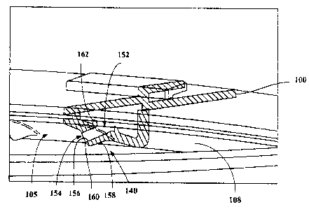
In the exemplary embodiment, each nozzle 140 has a length longer
than the thickness of bottom wall 105, and includes an inlet 152, an outlet
154, an
inner diameter 156, and an outer diameter 158. Outlet 154 further includes an
end
surface 160 substantially perpendicular to a flow of water through outlet 154,
which
facilitates reducing water sticking onto end surface 160 when water exits from
outlet
154. In an exemplary embodiment, end surface 160 is approximately from 85 to
90
degrees with respect to the flow of water through outlet 154. Outlet 154
partially and
smoothly submerges into outer surface 108, such that a portion of outlet 154
is
-7-
CA 02534242 2006-01-27 09HL25614
positioned within an area defined by outer surface 108 and is unitary with
outer
surface 108.
In the exemplary embodiment, each nozzle 140 further includes a boss
162 protruding into channel 110 and surrounding inlet 152. In an exemplary
embodiment, boss 162 keeps an equal distance with respect to inlet 152, and is
elliptical in shape. It is contemplated, however, that the shape and the
height of boss
162 may be altered in alternative embodiments. Although the flow rate in
nozzles 140
may vary when a first group of nozzles 140 are aligned with the direction of
water
flow and a second group of nozzles 140 is aligned against the direction of
water flow
in the corresponding portion of channel 110, boss 162 facilitates reducing
such flow
rate variation due to different nozzle alignments with respect to the channel
flow
direction.
Figure 6 is a top elevational and cutaway view of an alternative spray
ring 200 applicable to washing machine 10 shown in Figure 1, and Figure 7 is
an
enlarged cutaway view of spray ring 200 shown in Figure 6. In the exemplary
embodiment, spray ring 200 includes a ring-shaped channel 210 defined therein,
a
water inlet 212 in flow communication with channel 210, a baffle 214
positioned
adjacent water inlet 212, and a plurality of nozzles 240 arranged thereon.
In an exemplary embodiment, water flows in two directions in channel
210, such that nozzles 240 are divided into a first set of nozzles 240 aligned
with the
direction of water flow in the corresponding portion of channel 210 and a
second set
of nozzles 240 aligned against the direction of water flow in the
corresponding
portion. As such, the flow rate in the first set of nozzles 240 may be greater
than that
of second set of nozzles 240.
In the exemplary embodiment, baffle 214 is positioned substantially
halfway between water inlet 212 and a neighboring nozzle 240, and partially
blocks
chaimel 210 to reduce water flow toward the first set of nozzles 240 which
originally
has a higher flow rate therein. Specifically, baffle 214 reduces the cross
sectional area
of channel 210 by approximately 25% to 40%. More specifically, baffle 214
reduces
-8-
CA 02534242 2006-01-27 09HL25614
the cross section area of channel 210 by approximately 40%. As such, baffle
214
reduces the water flow through the first set of nozzles 240, and facilitates
realizing an
even flow of water in all nozzles 240 around channel 210.
In an exemplary embodiment, channel 210 further includes a blocking
portion 242 positioned halfway along channel 210 and corresponding to water
inlet
212. Blocking portion 242 partially blocks channel 210. Specifically, blocking
portion 242 blocks approximately 80% of the cross sectional area of
channe1210. It is
contemplated, however, that blocking portion 242 may be removed from
channe1210
in alternative embodiments or blocking portion 242 may block the entire cross
sectional area of channel 210.
Figure 8 is a cross-sectional view of nozzle 240 applicable to spray
ring 200 shown in Figure 6, and Figure 9 is a perspective view of nozzle 240
shown in
Figure 8. Spray ring 200 also includes a bottom wall 244 having an outer
surface 246,
and a plurality of nozzles 240 extending through bottom wall 244 and extending
into
channe1210.
In the exemplary embodiment, each nozzle 240 also has a length longer
than the thickness of bottom wa11244, and includes an inlet 252, an outlet
254, and a
nozzle channel 256 extending therebetween. A portion of outlet 254 further
includes
an end surface 258 substantially perpendicular to a flow of water through
outlet 254,
which facilitates reducing water sticking onto end surface 258 when water
exits from
outlet 254. End surface 258 is recessed with respect to outer surface 246, and
each
nozzle 240 further includes a partially cylindrical cutout 260 defined on
outer surface
246 and partially surrounding end surface 258. In an exemplary embodiment,
cutout
260 has a diameter at least 0.1 inch greater than the diameter of nozzle
channel 256,
which facilitates preventing water collecting in cutout 260 and sticking on
outer
surface 246.
In one embodiment, at least some nozzles 240 further include a baffle
(not shown) positioned within nozzle channel 256 in lieu of baffle 214 (shown
in
Figure 7) positioned within channe1210. Specifically, the nozzle baffle is
positioned
-9-
CA 02534242 2006-01-27 09HL25614
in nozzle channel 256 of each of the first set of nozzles 240 which are
aligned with the
water flow direction, such that the nozzle baffle reduces water flow through
the first
set of nozzles 240 compared to the second set of nozzles 240 for obtaining an
even
flow rate in all nozzles 240 around channel 210. In one embodiment, each
nozzle 240
further includes a boss (not shown) having a similar configuration as boss 162
(shown
in Figure 4) and surrounding inlet 252.
Figure 10 is a cross-sectional view of an alternative nozzle 340
applicable to spray ring 200 shown in Figure 6. Nozzle 340 is similar to
nozzle 240
(shown in Figure 8), and includes an outlet 342 partially recessed with
respect to outer
surface 246, and a recess 344 defined on outer surface 246 and adjacent outlet
342. A
portion of outlet 342 also includes an end surface 346 substantially
perpendicular to a
flow of water through outlet 342. Recess 344 is positioned adjacent end
surface 346,
and cooperates with end surface 346 to facilitate minimizing water channeling
outward from outlet 342 sticking onto outer surface 246.
In one embodiment, nozzles 240, 340 (shown in Figures 8, 10) are
employed on spraying ring 100 (shown in Figure 3) to obtain at least some of
the
benefits of the present invention. In another embodiment, nozzles 140 (shown
in
Figure 4) are employed on spray ring 200 (shown in Figure 6).
Figure 11 is a top elevational view of spray ring 100 shown in Figure 4
mounted on washing machine 10 shown in Figure 1, and Figure 12 is a
perspective
cutaway view of spray ring 100 mounted on washing machine 10. Alternatively,
spray
ring 200 is employed on washing machine 10 to obtain a similar rinsability in
other
embodiments.
In a rinse cycle of the washing operation, nozzles 140 channel water
into wash tub 30 in a non-overlapping manner and in a non-radial direction
with
respect to wash tub 30. In an exemplary embodiment, nozzles 140 direct water
outward from outlet 154 at an angle between approximately 35 and 50 degrees
with
respect to outer surface 108 (shown in Figure 2) and to a predetermined
location.
Specifically, nozzles 140 direct water outward from outlet 154 at an angle
between
-10-
CA 02534242 2006-01-27 09HL25614
approximately 39 and 45 degrees with respect to outer surface 108. Each nozzle
140
channels water to a location within a space approximately 10 inches upward
from a
bottom wall 350 of basket 32 and approximately 4 inches inward from a sidewall
352
of basket 32. The space is generally the location of the laundry after wash
spin is
completed, such that water directed by each nozzle 140 impinges on the laundry
to
facilitate a good rinse and avoid water waste. Each nozzle 140 directs water
forming
a trajectory 354. Trajectories 354 of nozzles 140 of the same group are
substantially
parallel with each other.
The nozzle has a length greater than the side wall of the spray ring,
which facilitates more accurately directing water to the predetermined
location. The
water valve controls the flow rate in the channel within a predetermined
range, the
ribs, the blocking portion, and the baffle also facilitate the even flow rate
in each
nozzle to avoid wasting water.
The methods and apparatus described herein facilitate rinsing the
laundry using less water than is required in a known washing machine.
Specifically,
the spray nozzles described herein facilitate directing an increased quantity
of water to
the laundry while reducing a quantity of water wasted compared to known
washing
machines. Accordingly, the methods and apparatus described herein facilitate
providing clean clothes while substantially reducing a quantity of water
consumed to
clean the clothes compared to known washing machines. Additionally, the
apparatus
described herein facilitates avoiding a re-circulating rinse water
configuration, a
considerable amount of additional materials and assemblies are saved, such
that the
present invention obtains good rinsing with low water consumption and low
manufacturing cost.
While the invention has been described in terms of various specific
embodiments, those skilled in the art will recognize that the invention can be
practiced
with modification within the spirit and scope of the claims.
-11-