Note: Descriptions are shown in the official language in which they were submitted.
CA 02534256 2006-01-27
CONICAL REFINER PLATES WITH
LOGARITHMIC SPIRAL TYPE BARS
Background of the Invention
The present invention relates to refining cones and plate segments for
refining cones, and more particularly to the shape of the bars that define the
refining elements of the cones or conical segments.
Disc or conical refiners for lignocellulosic material, ranging from saw
dust to wood chips, are fitted with refining plates or segments. The material
to
be refined is treated in a gap defined between two refining cones rotating
relative to each other. The material moves in the grooves formed between
bars located on the conical surfaces, providing a transport function and a
mechanism for material stapling on the leading edges of the crossing bars.
The instantaneous overlap between the bars located on each of the two cone
faces forms the instantaneous crossing angle. The crossing angle has a vital
influence on the material stapling or covering capability of the leading
edges.
Conventional bar geometries, particularly parallel straight line, radial
straight line, and curved in the form of inviolate arcs on circular evolutes,
as
well as projections thereof from planar reference surfaces onto conical
surfaces, show a change of bar crossing angle with respect to radial position
within refining zones. Parallel straight-line patterns show furthermore a
change of bar angle with respect to peripheral position within a field of
parallel
bars.
Since bar crossing angle is a determining factor for covering
probability, a variation in bar angle leads to a variation in covering
probability
as well. Therefore an inhomogeneous distribution of material in the gap as a
function of radial and angular position is unavoidable by conventional bar
designs. Representative patents directed to particular configurations of bars
and grooves on segments for refiner plates, include: US 6,276,622 (Obitz),
"Refining Disc For Disc Refiners", Aug. 21, 2001; US 4,023,737 (Leider et
al.),
1
CA 02534256 2006-01-27
"Spiral Groove Pattern Refiner Plates", May 17, 1977; and US 3,674,217
(Reinhall), "Pulp Fiberizing Grinding Plate", July 4, 1972.
Summary of the Invention
In order to provide a uniform covering along the length of the bars
independent of radial or angular position, the bars should be shaped in a form
that provides constant bar crossing angle regardless of position.
Accordingly, the object of the present invention is to provide a refining
element bar shape with the desired feature of constant bar and thus constant
crossing angle to promote a more homogeneous refining action.
A conical refiner plate and associated segments wherein the bars
assume the shape of a logarithmic spiral or projected logarithmic spiral,
satisfy the foregoing object of the invention. As used herein, "logarithmic
type
spiral" should be understood as consisting of a logarithmic spiral in two
dimensions or such logarithmic spiral projected in three dimensions.
The invention can in one aspect be characterized as a refining cone
having a working surface, a radially inner edge and a radially outer edge, the
working surface including a plurality of bars laterally spaced by intervening
grooves and extending generally outwardly toward the outer edge across the
surface, wherein the bars are curved with the shape of a logarithmic type
spiral.
From another aspect, the invention can be characterized as a conical
refiner including first and second opposed, relatively rotatable refining
cones
which define a refining space or gap, the first and second cones each having
a plate with a radially inner edge, a radially outer edge, and a working
surface
including a plurality of bars generally extending outwardly toward the outer
edge across the surface, wherein the plurality of bars on at least the first
cone
are curved with the shape of a logarithmic type spiral.
During operation of the refiner, each of the bars on the first cone will be
crossed in the refining space by a plurality of bars on the second cone,
2
CA 02534256 2006-01-27
thereby forming instantaneous crossing angles. For each of the bars on the
first cone, the crossing angle is a substantially constant nominal angle.
Preferably for each of the plurality of bars on the first cone, all
instantaneous
crossing angles are within +1- 5 degrees of the nominal crossing angle.
An additional feature of the logarithmic type spiral is the variability of
groove width, i.e., the distance between adjacent bars with respect to radial
position. The grooves increasingly open in the direction of stock flow, which
prevents plugging of the grooves with fibers and tramp material.
Brief Description of the Drawings
Figure 1 is a schematic of an internal portion of flat disc wood chip
refiner, illustrating the relationship of opposed, relatively rotating discs,
each
of which carries an annular plate consisting of a plurality of plate segments;
Figure 2 is a photograph of a disc refiner plate segment incorporating
refiner bars in the shape of logarithmic spirals;
Figure 3 is a schematic by which the mathematical representation of a
logarithmic spiral on a disc plate can more easily be understood;
Figure 4 is a schematic representation of a flat disc bar curvature for
the value alpha = 60 deg;
Figure 5 is a schematic representation of a flat disc bar curvature for
the value alpha = -30 deg;
Figure 6 is a schematic plan view similar to Figure 2, showing an
embodiment wherein only the outer of a plurality of refining zones has bars in
a logarithmic spiral pattern;Figure 7 is schematic of a conical refiner having
inner and outer conical
plates defining an annular refining gap through which material flows in the
direction from the smaller diameter to the larger diameter;
3
CA 02534256 2012-10-24
Figure 8 is an elevation view of the inner, rotor cone of a three-zone
conical refiner showing the conical refining plate resting with the smaller
diameter
edge on a horizontal surface and the rotation axis extending vertically;
Figure 9 is a plan view of an individual plate segment from among the
plurality of segments that constitute the conical plate of Figure 8;
Figure 10 is a perspective view of the plate segment of Figure 9; and
Figures 11A and 11B represent a group of bars defined by the
mathematical expression in the first step of the present method, and Figures
110
and 11D represent how the same group of bars would project onto a three
dimension (X-Y-Z) conical surface when viewed perpendicularly to the surface
to
produce a bar pattern such as shown in Figure 9.
Description of the Preferred Embodiment
The present invention will be described with reference to my prior
invention directed to refiner plates having bar and groove patterns in the
shapes
of a logarithmic spirals, as disclosed in U.S. Patent Publication No.
US2004/0149844. In essence, the common inventive concept is the constant bar
angle and thus constant bar crossing angle independent of the angular position
or position traversing at least one zone along a line from the inner toward
the
outer edge of the face of the plate. The bars on the flat disc plate actually
follow
the curves defined by the mathematical expression for a logarithmic spiral,
whereas for a conical plate, the bars do not necessarily follow a true
logarithmic
spiral but are derived from a true logarithmic spiral.
For the conical plates, a logarithmic spiral pattern is first defined in a
planar surface (on an imaginary X-Y plane), and then this logarithmic spiral
is
projected onto a three-dimensional surface in X-Y-Z space. Bars formed
according to the former are true logarithmic spirals, whereas bars formed
4
CA 02534256 2006-01-27
according to the latter are distortions of true logarithmic spirals, but can
nevertheless be referred to as "logarithmic type spiral" bars. They are not
only derived from true logarithmic spirals, but also preserve in X-Y-Z space,
the constant bar angle and the constant bar crossing angle.
For a better understanding of the conical plates, the logarithmic spiral
for disc plates will first be described.
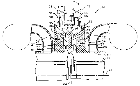
Figure 1 is a schematic showing a flat disc refiner 10 with casing 12 in
which opposed discs are supported, each of which carries an annular plate or
circle consisting of a plurality of plate segments. The casing 12 has a
substantially flat rotor 14 situated therein, the rotor carrying a first
annular
plate defining a first grinding face 16 and a second annular plate defining a
second grinding face 18. The rotor 14 is substantially parallel to and
symmetric on either side of, a vertical plane indicated at 20. A shaft 22
extends horizontally about a rotation axis 24 and is driven at one or both
ends
(not shown) in a conventional manner.
A feed conduit 26 delivers a pumped slurry of lignocellulosic feed
material through inlet opening 30 on either side of the casing 12. At the
rotor,
the material is re-directed radially outward through the coarse breaker region
32 whereupon it moves along the first grinding face 16 and a third grinding
face 34 juxtaposed to the first face so as to define a right side refining
zone 38
therebetween. Similarly, on the left side of the rotor 14, material passes
through the left refining zone 40 formed between the second grinding face 18
and the juxtaposed grinding face 36.
A divider member 42 extends from the casing 12 to the periphery, i.e.,
circumference 44, of rotor 14, thereby maintaining separation between the
refined fibers emerging from the refining zone 38, relative to the refined
fibers
emerging from the refining zone 40. The fibers from the right refining zone
are discharged from the casing through the discharge opening 46, along
discharge stream or line 56, whereas the fibers from the left refining zone 40
are discharged from the casing through opening 48 along discharge line 58.
5
CA 02534256 2006-01-27
Thus material to be refined is introduced near the center of a disc, such
that the material is induced to flow radially outwardly in the space between
the
opposed refining plates, where the material is influenced by the succession of
groove and bar structures, at a "beat frequency", which is dependent on the
dimensions of the grooves and the bars, as well as the relative speed of disc
rotation. The material tends to moves radially outward, but the shape of the
bars and grooves is intentionally designed to produce a stapling effect and a
retarding effect whereby the material is retained in the refining zone between
the plates for an optimized retention time.
Although the gap between plates where refining action occurs is
commonly referred to as the "refining zone", the opposed plates often have
two or more distinct bar and groove patterns that differ at radially inner,
middle, and outer regions of the plate; these are often referred to as inner,
middle, and outer "zones" as well.
In accordance with the underlying concept of the present invention, the
further variable of the bar-crossing angle is maintained substantially
constant.
This is accomplished by the bars substantially conforming in curvature to the
mathematical expressions for a logarithmic spiral. In particular, during
operation of the refiner each of the bars on the first disc will be crossed in
the
refining space by a plurality of bars on the second disc, thereby forming
instantaneous crossing angles, and for each of the bars on the first disc, the
crossing angle is a substantially constant nominal angle.
With reference to Fig. 2, there is shown a refining segment 54, which is
disposed on the inside of a refining disc and which is intended for coaction
with the same or different kind of refining segments on an adjacent refining
disc on the other side of the refining gap. Several segments as shown in Fig.
2 are typically secured side-by-side to a base (e.g., rotor or stator) to form
a
substantially circular (e.g., circular or annular) refining plate. The segment
has the general shape of a truncated sector of a circle. Each segment may
be mounted to the plate holder surface of the base by means of machine
6
CA 02534256 2006-01-27
screws inserted through countered bolt holes 56. Some refiner designs may
allow fastening the plates from the back, which eliminates the boltholes from
the face of the plate. In general segments are mounted on discs rotating
relative to each other, which could be achieved by the presence of one rotor
and one stator (single disc refiner), or by one rotor segmented on both sides
and operating against two stators (double disc refiner), or by several rotors
working against each other and a pair of stators (multi disc refiner), or by
counter-rotating discs.
Each refining disc segment can be considered as having a radially
inner end 58, a radially outer end 60, and a working surface therebetween,
the working surface including a plurality of bars 62 laterally spaced by
intervening grooves and extending generally outwardly toward the outer end
across the surface. Preferably all, but at least most, of the bars are curved
with the shape of a logarithmic spiral.
As is common for both low and high consistency refining of wood chip
or second stage material, the bars on a plate formed by the segments of Fig.
2 are arranged in three radially distinct refining zones 64, 66, 68, between
the
inner and outer plate edges 58, 60. A Z-shaped transition zone 70
accomplishes the material flow transition between the individual refining
zones. In this embodiment, the bars in each zone follow a logarithmic spiral.
The particular shape parameter (alpha) may be different for each zone, but
the shape parameter for each confronting zone on the opposed plate, would
preferably be the same.
This particular and unique shape provides the advantage of the
independence of bar angle from the location of the bar on the plate in a
particular refining zone. Since the particular shape of the logarithmic spiral
guarantees the bar intersecting angle with lines through the center of the
plate
to be constant, no bar angle and therefore crossing angle variation in the
course of the relative movement of rotor and stator segments occurs. Since
bar angle has a significant impact on refining action and bar covering
7
CA 02534256 2006-01-27
probability, any variation of bar and crossing angle will result in a
variation of
refining action. The invention achieves maximum homogeneity of refining
action by minimizing bar angle variation.
The width of the groove between two adjacent logarithmic spiral bars is
variable and increases with radial distance by the nature of the curve. Thus
the groove width at the ID of zone 68 is smaller than on the OD of the zone,
the OD of the outer edge 60 of the plate in this case. Therefore the open area
available for stock flow increases disproportional with increasing radius.
This
feature provides increased resistance against plugging in comparison to
parallel bar designs, where no groove width variation occurs.
With reference to Figure 3, the crossing angle 13 appears as the
intersecting angle between the tangents t1 and t2 to the two curves c1 and c2
(i.e., the curved leading edges of crossing bars) at the point of intersection
pi.
The angle 13 between the tangents remains constant, at every possible
crossing point. Each bar has an angle oc relative to the generatrix y passing
through the center point pc.
Figures 4 and 5 are schematic representations of the bar curvature for
two different values of alpha. Figure 4 shows the curvature for alpha = 60
degrees, and Figure 5 shows the curvature for alpha = -30 degrees. The
designer has the flexibility to select the angle between plus 90 degrees and
minus 90 degrees.
The mathematical expression for the shape of the logarithmic spiral
bar, defines any given bar which in the limit, is a line of infinitesimal
thickness
such that the location of any given point on the line is a function of the
angular
position (phi) of the point relative to a reference radius or diameter through
the
center (along the generatrix of the coordinate system) and the intersecting
angle (alpha) between the tangent to the curvature of the bar at the point,
and
the generatrix. This mathematical relationship is used in a practical sense,
to
design functional bar patterns.
8
CA 02534256 2006-01-27
This would typically be performed in a computer assisted design (CAD)
system which is readily programmed to incorporate the mathematical model
and which has an output that can translate the mathematical modeling of the
segment, to equipment for producing a tangible counterpart from a segment
blank. This would proceed by having one spiral curve calculated in radial
increments, thereby establishing the "mother" of all the other bars, by
determining the starting radius as well as the starting angle (arrived at by
adding a constant to the calculation result). The one full curve (representing
the leading edge of the "mother" bar) will be located somewhere on the
segment. In a CAD system, the curve will not necessarily be a
mathematically continuous, full logarithmic spiral but rather can be
approximated by a spline fit. The accuracy of the spline depends on the radial
increments selected. Moreover, the first few points on the spline, close to
the
inside diameter of the segment, may not match closely to the theoretically
logarithmic spiral, but this artifact of the CAD system has little adverse
consequence if limited to the small radius at the inside diameter. The typical
CAD system (e.g., AutoCad ) then allows the user to offset the trailing edge
of the mother bar, thereby giving the bar a selected width which is
established
from the inner to the outer radius of the segment. The mother bar can then be
copied and rotated to fill the segment. For example, the user can specify the
bar width at a given radius, the number of bars for the segment, or the
minimum desired groove width at a given radius, etc.
It should be appreciated that, in view of modern manufacturing
techniques, the term "logarithmic spiral" as used herein, although based on a
mathematical expression, may in practice only approximate the mathematical
expression through a series of straight or curved lines each of which is
relatively short as compared with the full length of the curve from the inner
to
the outer radius of the segment, or from the inner radius to the outer radius
of
a given zone in the segment. Similarly, a reasonable degree of latitude
should be afforded the inventor in reading the term "logarithmic spiral" on
the
9
CA 02534256 2006-01-27
shape of curved bars according to which one of ordinary skill in the relevant
field of endeavor would recognize an attempt to maintain conservation of the
bar crossing angle in the radial direction on a given segment, or within the
zone of a given segment. The benefit of the present invention can be realized
to a significant extent relative to the prior art, even if the logarithmic
spiral is
merely approximated, e.g., if the crossing angle is maintained within +1- 10
degrees from the radially inner end to the radially outer end of a given bar.
Variations of the invention can be readily understood without reference
to other drawings. For example, in the context of the invention as
implemented in a refiner, a first refining disc faces a second relatively
rotatable refining disc with a refining space there between. Either both or
only one of the first and second discs has a shape and surface with an inner
end and an outer end including a plurality of bars generally extending
outwardly toward the outer end across the surface, with the plurality of bars
being curved with the shape of a logarithmic spiral. If both discs have
segments with curved bars following the same logarithmic spiral, constant bar
crossing angles will be achieved. If the facing discs both have logarithmic
spiral bar curvature, but with different parameters alpha, some design
variability for specialty purposes can be achieved. If only one disc has a
logarithmic spiral bar curvature, and the facing disc has a conventional bar
pattern, the result will still advantageously reduce bar crossing angle
variation
relative to two facing discs having the same such conventional pattern.
In another embodiment the logarithmic spiral bar curvature is present in
fewer than all the radial zones. Figure 6 is a schematic plan view similar to
Figure 2, showing an embodiment of a segment 54' wherein only the outer 68'
of a plurality of refining zones on working surface 62' has bars in a
logarithmic
spiral pattern. In a two or three zone plate, the radially outermost zone
would
preferentially have the logarithmic spiral bars, because the number of fiber
treatments increases with disc radius according the third power of the radius.
In such case, the inner zone(s) 66' would preferably follow the so-called
10
CA 02534256 2006-01-27
"constant angle" pattern, as exemplified in the 079/080 pattern available from
Durametal Corp. for the Andritz Twin-Flo refiner and shown only schematically
in Figure 6.
Figures 7-11 show how the previously described concept is
implemented in a conical refiner. Figure 7 shows a conical refiner 72 with a
rotating shaft 74 carrying rotor 76 with associated conical plate 78 and
stator
80 with associated conical plate 82 thereby defining the refining gap 84
therebetween. Feed material enters at feed conduit 86, passes into the
refining gap at 88 and is discharged through discharge conduit 90.
The invention may be described mathematically.
(1): Construction of a Logarithmic Spiral on a Flat Reference Surface
Using polar coordinates r and up, the following transformation function
to Cartesian coordinates would apply:
X = r = cos 99
y = r = sin q2
r2 =2 + y2
The general shape of the logarithmic spiral bar is represented by
r = a = ek
k = cot a
k = 0 circle =
where "a" is a scale parameter for r and a (alpha) is the intersecting angle
between any tangent to the curve and a line through the center (generatrix) of
the coordinate system.
11
CA 02534256 2006-01-27
In the case of alpha = 90 deg or ¨90 deg, the tangent of the curve in
any point would be orthogonal to the generatrix, and the curve is therefore a
circle with radius a.
This unique bar shape provides not only identity for individual bar
angles but also the so-called cutting or crossing angle assumes the same
identity throughout the whole refining zone.
(2): Projecting the Logarithmic Spiral from a Plane
Orthogonal to the
Cones Axis onto the Conical Surfaces
The described logarithmic spiral is well-defined for the x-y plane. This
invention utilizes the constant angle nature of this special curve and
projects it
from a plane orthogonal to the axis of the cone on its surface.
In this process the curve assumes a three-dimensional form in the x-y-
z continuum. The inclination and curvature of the conical surface makes the
length of the projection differ from the original in the x-y plane. This leads
to a
change in the value of bar / crossing angles, bar widths, groove widths and
edge lengths from the original values in the x-y plane. Nevertheless, the
constant angle nature of the curve with respect to the cone's generatrix
remains preserved in this process. This is the basis for the term logarithmic
type spiral.
The transformation functions for the spiral angles are
(
.= atan trati(acone 180 180
sin(20. 180)it it
In this formula half of the cone angle to its axis is set to 20 degrees
(appears
in the sines part). Any cone angle deviation would show up there. The
12
CA 02534256 2006-01-27
variable acone means the bar angle target for the logarithmic spiral type
curve
on the cone, while a nominates the logarithmic spiral bar angle target in the
original x-y plane.
The lengths involved in this transformation develop according to the
following formula:
bw
bwcone
12
sin 1190 ¨ acone). 3 I 4- 12
cos[(90 ¨ acone).-7-1 1801
180]
2
sin(20-1¨t 1
180)
gwl
gwlcone
12
12 cos[(90 ¨ acone). n
s ini( 90 ¨ acone)--21- I + 180j
\ 2 180j
sin(20.2-1 180 )
As above, the cone angle was assumed to be 20 degrees, appearing in the
sines formula. The bwcone nominates the barwidth to be achieved on the
cone after projection, while bw gives the bar width target for the logarithmic
spiral in the x-y plane. The same rationale pertains to gw1cone and gw1.
Figures 8-10 show a detailed view of one embodiment of a conical
plate 78 and associated segment 92. Figures 11A-D show the generating
logarithmic spiral in the X-Y plane superimposed on an X-Y plane projection
of the refiner plate segment. In this case, the constant angle is 54 degrees.
This angle changes as it is projected onto the conical surface (to 25 degrees)
but the new angle remains constant on the conical surface with respect to a
ray on that conical surface.
The invention includes a method for manufacturing a set of opposed
plates including the steps of forming a pattern of bars and grooves that
13
CA 02534256 2006-01-27
substantially conform to the foregoing mathematical expressions. As shown
in Figure 7, the conical inner plate 78 associated with rotor 76 has the bar
and
groove pattern around the convex outer surface. One embodiment of the
plate and associated segments is shown in Figures 8-10. It can be readily
understood that the confronting, outer conical plate 82 attached to the stator
80 would have a complimentary, concave inner curvature. Thus, in the
manufacture of a set of plates for a conical refiner, one collection of
segments
having a convex outer surface would be selected and coordinated for
arrangement side by side to form a first, inner conical plate, and another
plurality of concave segments would be selected and coordinated for
arrangement side by side to form a second, outer conical plate, the plates
thus associated as a set for confronting installation in a conical refiner.
Although the invention herein has been described with reference to a
particular, preferred embodiment, it is to be understood that these
embodiments are merely illustrative of the principles and applications of the
present invention. It is therefore to be understood that numerous
modifications
can be made to the illustrative embodiments and that other arrangements
may be devised without departing from the spirit and the scope of the present
invention.
14